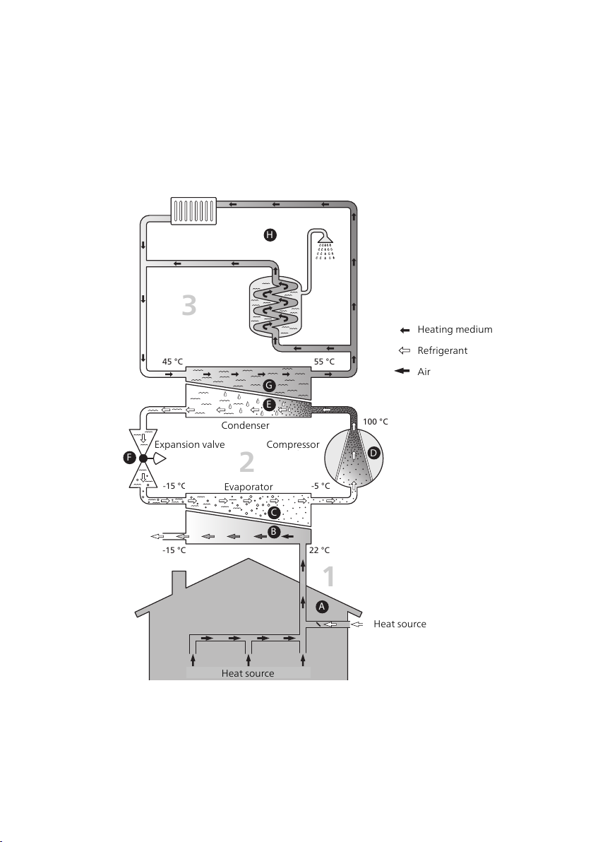
Exhaust air module function
An exhaust air module uses the heat that is in the building's ventilation
air to heat up the house. The conversion of the ventilation air's energy
to residential heating is done in three different circuits. From the outgoing
ventilation air (1), free heating energy is retrieved from the house and
transported to the exhaust air module. The exhaust air module increases
the retrieved heat's low temperature to a high temperature in the refri-
gerant circuit, (2). The heat is distributed around the building in the
heating medium circuit (3).
Ventilation air
The hot air is transferred from the rooms to the heat pump via the exhaust
air module.
A
The fan then routes the air to the exhaust air module's evaporator. Here, the
air releases the thermal energy to the brine and the air's temperature drops
significantly. The cold air is then blown out of the house.
B
Refrigerant circuit
A liquid, a refrigerant, circulates in a closed system in the exhaust air module,
which also passes the evaporator. The refrigerant has a very low boiling
point. In the evaporator the refrigerant receives the heat energy from the
ventilation air and starts to boil.
C
The gas that is produced during boiling is routed into an electrically powered
compressor. When the gas is compressed, the pressure increases and the
gas’s temperature increases considerably, from approx. 5°C to approx. 80°C.
D
From the compressor, gas is forced into a heat exchanger, condenser, where
it releases heat energy to the heating system in the house, whereupon the
gas is cooled and condenses to a liquid form again.
E
As the pressure is still high, the refrigerant can pass an expansion valve,
where the pressure drops so that the refrigerant returns to its original tem-
perature. The refrigerant has now completed a full cycle. It is routed to the
evaporator again and the process is repeated.
F
Heat medium circuit
The heat energy that the refrigerant produces in the condenser is retrieved
by the climate system's water, heating medium, which is heated to 55 °C
(supply temperature).
G
Ventilation
The hot air is transferred from the rooms to the heat pump via the exhaust
air module.
J
The fan then routes the air to the exhaust air module heat exchanger. Here,
the air releases the heating energy to the brine and the air's temperature
drops significantly. The cold air is then blown out of the house.
K
9Chapter 2 | The heating installation – the heart of the houseNIBE F135