Cressi Aquapro Manual

Manuale d’uso
Direction for use
Manuel d’instructions
Bedienungsanleitung
Manual de istrucciones
EQUILIBRA ORI
B.C.’S JACKE S
GILE S S ABILISA EURS
ARIERJACKE S
CHALECOS HIDROS Á ICOS
Via Gelasio Adamoli, 501 - 16165 - Genova - Italia
el. +39 010 830.79.1 - Fax +39 010 830.79.220
CO_2016_Layout 1 31/03/16 16.29 Pagina 1

23
English
CRESSI BCDS
Congratulations on your purchase of a CRESSI product. You have se-
lected an excellent product. Its design is the result of continuous research
and development and it has been carefully constructed in compliance with
CRESSI quality standard, thus ensuring pleasant and absolutely safe di-
ving for a long time.
INTRODUCTION
BCDs are of utmost importance for underwater diving activities due to the
fact that they make dives with diving regulators more comfortable, more
practical and safer. In fact, they can be used to transport cylinders and to
control the position, when diving and on the surface, through the inlet or
release of air into/out of the cell. In this way, the diver’s specific weight will
vary, making him/her lighter and more dynamic. Its function accounts for
the abbreviation “BCD”, i.e. Buoyancy Control Device, the name that is
given to these jackets.
GENERAL WARNINGS
CAUTION!
FAILURE TO COMPLY WITH THE PRECAUTIONS LISTED
BELOW COULD CAUSE SERIOUS DAMAGE OR EVEN
DEATH.
In order to properly use the diving equipment described in this manual, you
must be properly trained (theory and practice), which can only be achieved
by obtaining a diver certification from a recognised certification agency.
The use of this device by people without a certification is highly dangerous
and may cause serious injuries or even death. It is also essential to have
fully read and understood this manual.
CAUTION! This manual does not replace the
training foreseen by the suitable diving courses given
by recognised schools in any way.
CE CERTIFICATION
The CE marking regulates the release to the market conditions and the es-
sential safety and health requirements of Personal Protective Equipment.
Such marking is therefore synonym of legality, safety and quality of the
products that meet such standards.
CRESSI BCD is a Personal Protective Equipment that complies with the
provisions of Directive 89/686/EEC and the national regulations that im-
plement EN 250 and EN 1809 harmonised standards.
The EC-type examination certificate has been issued by Notified Body No.
0474: RINA Via Corsica 12, 16128 Genoa, Italy.
All products bear the relevant marking. As required by the CE standards,
CRESSI BCDs are certified to be used up to 50 metres deep.
CAUTION!
THE BCD IS NOT A LIFEJACKET; IT DOES NOT GUA-
RANTEE A HEAD UP POSITION OF WEARER AT THE
SURFACE.
FEATURES
In order to meet the varied needs of divers, Cressi BCDs have different
features depending on the various models offered in the catalogue. We
will explain each of such features below so that they can be properly used.
24 English
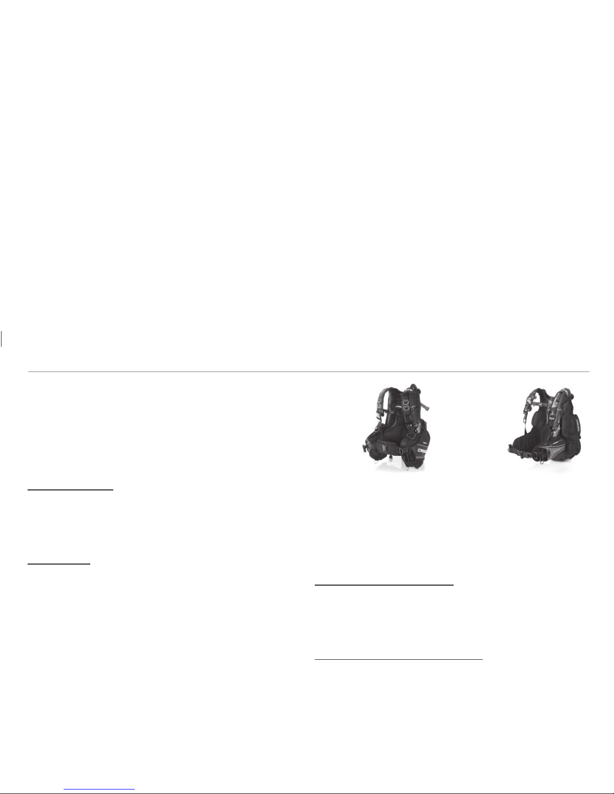
Beck air cellStandard
air cell
AIR CELL
The air cell is the watertight part of a BCD that is inflated and deflated in
order to vary the diver’s position.
A harness, or part of it, is added to the air cell so that it can be worn and the
cylinder can be positioned on it. There are different types of cells accor-
ding to their shape, the type of containing cell and the ascending buoyancy
that they are able to exert.
STANDARD AIR CELL
The Standard air cell is the most traditional and comfortable one. Its shape
is similar to a gilet; therefore, the air contained in it is distributed both at the
back and to the sides and front of the diver. Its main feature is that it wraps
the diver and makes him/her keep in vertical position.
BACK AIR CELL
These types of BCDs are characterised by an air cell located in the rear
part of the diver so as to release the front part and make the BCD lighter
and less voluminous. In addition, when it is inflated, it does not tighten
the body, while it is kept independent from the straps, thus giving you a
sensation of complete freedom of movement.
CAUTION: In the BCDs with back air cell, while being on the surface,
the air mass tends to position the diver horizontally with his/her down.
In case of loss of consciousness, the head remains immersed. Therefo-
re, they are to be used by expert divers who have taken specialisation
courses.
BACKPLATE
The backplate of a BCD is the rear part that enables a correct assembly
among the cylinder, the harness and the air cell, so between the BCD and
the diver. It is a very important part because it bears the entire weight of
the diving regulator (fig. 11-12-13).
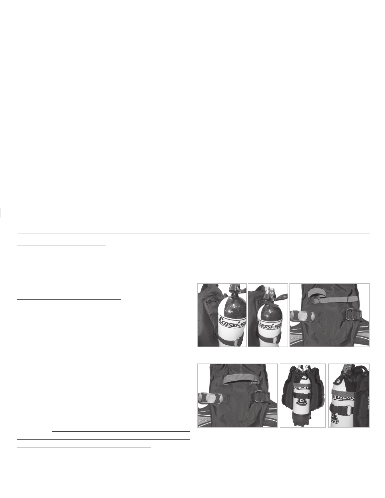
SINGLE STRAP RIGID BACKPLATE
Cressi rigid backplate has been manufactured with very resistant and
light engineering plastics, and it can correctly hold the cylinder by using
one single strap. It has several slots to adjust the harness and a practical
handle to carry the entire unit.
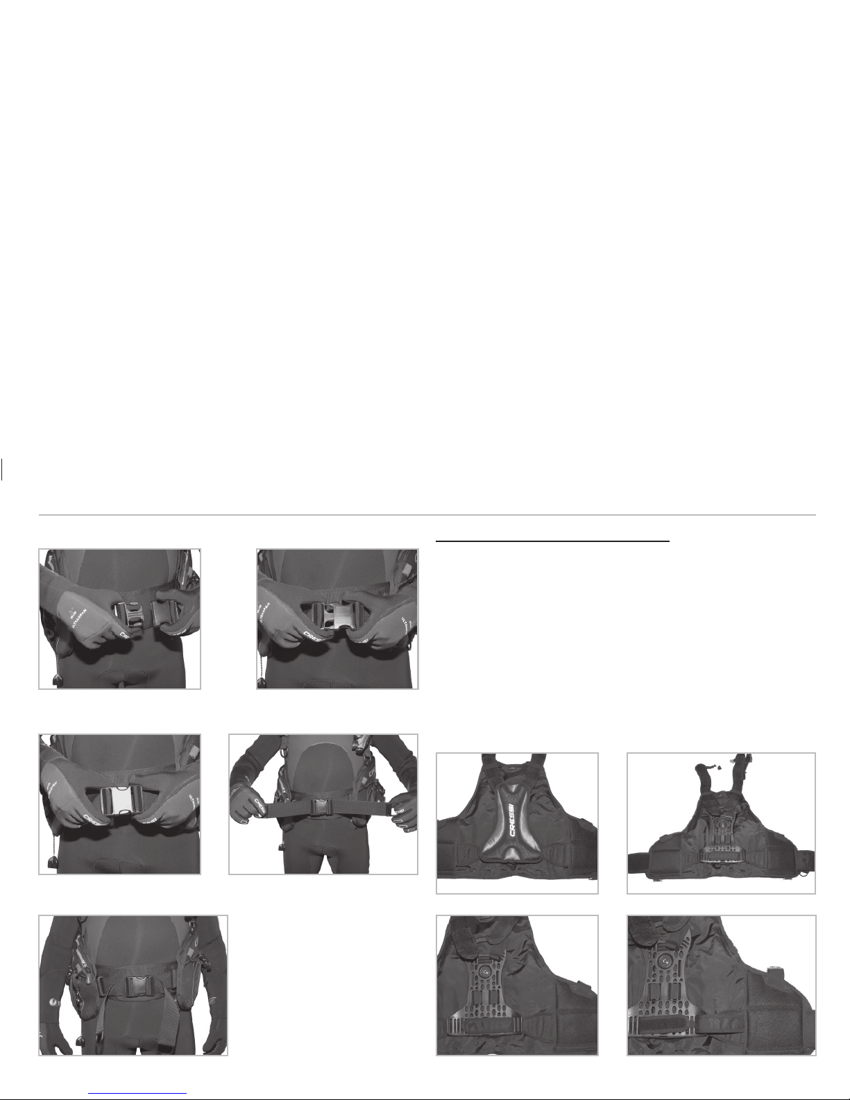
Securing the cylinder with the rigid backplate
In the back of Cressi rigid backplate, there is a strap to secure the cylinder.
This is an essential component of the BCD because it bears the entire
weight of the cylinder, and it is extremely important to tighten it properly
by means of its special locking buckle. Such buckle is supplied already
correctly fitted (fig. 12); however, it is still important to learn how to do it
properly. To such end, see the figure below, drawings 1 to 5, which ex-
plains how to do it, step by step.

25
English
Once the buckle is fitted, install the cylinder by following the procedure
indicated below: Release the strap from the Velcro closure and loosen it as
shown in drawing 6. Position the cylinder, threading it from below with the
valves facing the BCD. Unthread the strap from the first slot of the buckle
(drawing 7). Open the buckle by turning it until it snaps open and tighten
the strap so that it holds the cylinder firmly (drawing 8). Close the buckle
partially and thread the tip of the strap back into the first slot (drawing 9).
Close the buckle completely and secure the strap with the Velcro closure
(drawing 10). Now the cylinder is correctly positioned (fig. 14-15).
CAUTION - Always wet the strap before using it to fasten the cylinder.
This is crucial for the diver’s safety- if the strap is dry, it could stretch when
submersed and so the cylinder may slip off.
Once the cylinder has been attached, keep the upper side of the backplate
from 5 to 10 cm below the valves (fig. 16), so that the diver’s head does not
bump against the regulator.
(11) (12) (13)
(14) (15) (16)
26
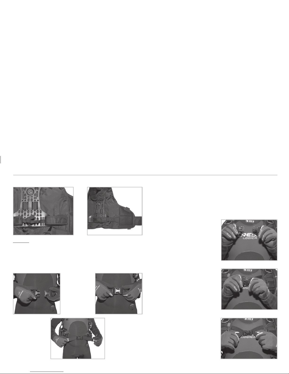
DOUBLE STRAP SOFT BACKPLATE
With respect to the rigid model made of plastic, the soft backplate can be
folded, thus making the BCD more compact and lighter so as to be carried
more easily. It has been manufactured with particularly resistant fabrics
that guarantee not only optimal grip of the cylinder, but also low weight
(fig. 17-19-20).
Securing the cylinder with the soft backplate
Unlike the rigid backplate, Cressi soft backplate has two straps for secu-
ring the cylinder. The first one – and main one – is located at the lower part
and it is very important because it bears the entire weight of the cylinder;
it is essential to tighten it properly by means of its special locking buckle.
The procedure has been described above in the section dealing with the
rigid backplate. The second strap, which is located at the upper part, is an
auxiliary strap and it has a simple Velcro closure or a buckle closure. Its
purpose is to keep the cylinder perfectly adhered to the high part of the
BCD backplate. Once the cylinder has been secured to the main strap,
tighten and close properly the auxiliary strap. There are two types of au-
xiliary straps: the first type wraps the cylinder completely and is locked
thanks to a Velcro strap and a ring with which its length can be adjusted
(fig. 19-20-21-22). Whereas the second type is locked thanks to a quick-
release buckle. In this case, you have to make the strap pass through the
cylinder neck (the part where the valves are screwed) (fig. 17-18).
CAUTION - Always wet the straps before using them to fasten the cylin-
der. This is crucial for the diver’s safety- if the straps are dry, they could
stretch when submersed and so the cylinder may slip off.
It is recommended to keep the auxiliary Velcro strap in the cylinder con-
stant diameter area (a little bit below the end of the neck curvature) to
prevent it from slipping off, thus losing effectiveness.
COMPATIBLE CYLINDERS
All diving cylinders with 10/12/15/18 Litre capacity or with 171 to 216 mm
diameters are compatible.
(17) (18) (19)
(20) (21) (22)
English

27
INTEGRATED WEIGHT POCKETS
Several BCD models have systems that enable to introduce the ballast
directly in some special pockets. Thanks to this solution, divers do not
have to wear the entire weighing system in the waist belt and, in case of
emergency, release is easier and more gradual.
CAUTION - For safety reasons, it is recommended to
keep the weight belt at the waist with a minimum amount
of weight in order to make the diver’s position manage-
able even in those situations in which the BCD weight
pockets have been completely released so as to avoid
dangerous uncontrolled ascents.
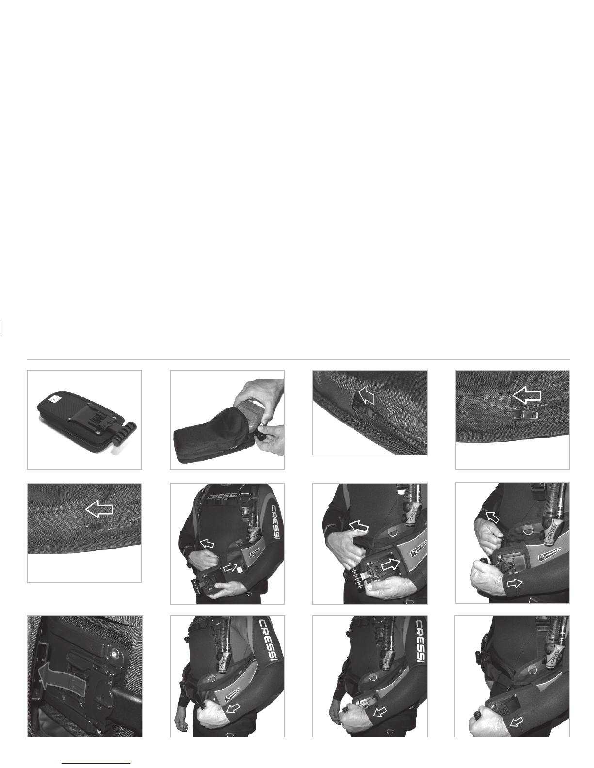
FLAT LOCK AID INTEGRATED WEIGHT POCKETS
The system consists in inserting the weight pockets horizontally in two sui-
table compartments located to the sides of the BCD. This system is locked
by means of suitable quick-release buckles that have been specifically de-
signed. In case of emergency, the latter may be released instantaneously
or alternatively.
THE POCKETS: Both lead-holding pockets (Fig. 23) are interchangeable
in order to make their positioning easier; however, one of their sides, mar-
ked by a label with the writing “this side out”, must always be positioned
towards the outside.
Maximum amount of ballast that may be inserted in each pocket (Fig. 24)
is 4.5 Kg / 10 lbs. Both may hold a total amount of 9 Kg / 20 lbs.
Cressi-sub recommend to load each pocket with the same amount of bal-
last, in order to obtain a correct balancing during your dive.
Once the ballast is inserted in the pocket, close the zip fully and tuck it in
to avoid interference with the release system (Fig. 25-26-27)
POSITIONING AND LOCK: The pocket may be positioned even while
wearing your jacket. Please follow these indications: catch the special “d–
shaped” ring of the pocket on the opposite side and pull, in order to get
the inside edge of the pocket to come off and make the positioning easier.
Then insert the pocket into the space provided.
Push the pocket inside holding it from below, making sure it slides freely
without any hindrance (Fig. 28). Keep pushing.
Use the handle and keep pushing (Fig.29). Keep pushing until you hear
the unmistakable click (Fig.30). Now, make sure the positioning is correct
and complete. If you don’t hear the sound of the “click”, check that the
male buckle, which is fixed to the pocket, is inserted correctly into the
female socket which is fixed to the inside space (Fig.31).
To release the ballast rapidly, catch the special handle fast and push firmly
forward (Fig. 32).
WARNING: Before carrying out this procedure make sure the handle and
pocket are not hindered by any rope, strip or anything else that might pre-
vent its release. Do not put lead or bulky objects in the next pockets which
might interfere with the release system.
The sound of the device release must be heard. Do not stop and keep
pushing so that the pocket starts sliding (Fig. 33).
Keep pushing until you feel the ballast weight on your arm (Fig. 34).
WARNING: Before diving, it is highly recommended to try the system
many times in order to get well acquainted with it.
Before diving make sure the system is correctly assembled and acquaint
your partner with its use and functioning. In case you have a great amount
of ballast, please pay particular attention while putting on your wet suit.
We recommend assistance to avoid any accidents.
English
28
23 24
25
26
27
28
29
30
31
32 33
34
“CLACK”
English
29
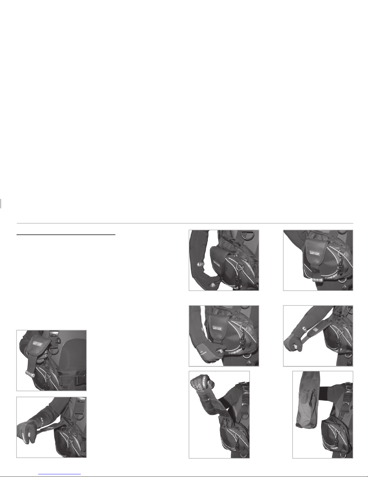
C-TRIM INTEGRATED WEIGHT POCKETS
C-Trim is a system of integrated weight pockets that consists in inserting
the weight pockets vertically in two suitable compartments located behind
the two accessory pockets. To release the pockets, you need to grasp the
handle and exert force towards the outside so that the strap uncouples
from the automatic push-button and from the Velcro closure (fig. 39-40).
Then, continue the movement, always outwards, but now also upwards so
as to detach the pocket from its Velcro strap and remove it from its com-
partment (fig. 41). If you continue pulling, it will be completely removed
(fig. 42). To put the pocket back, you just need to insert it into its com-
partment making sure that the two Velcro straps are in line (fig. 35). Once
in place, move the flap with the handle
close to the external part of the com-
partment and make the Velcro strap
coincide with the automatic push-but-
ton. Close the automatic push-button
(fig. 36-37-38). The maximum weight
to be inserted will be 5.0 Kg per pocket.
(35)
(36)
(37)
(41) (42)
(40)(39)
(38)
English

30
FIXED GRAVITY INTEGRATED WEIGHT POCKETS
This system is very simple; it consists in two fixed pockets located next to
the accessory pockets. When they are overturned downwards, the BCD
ballast falls down. Therefore, to release the ballast, you just need to open
the quick-release buckle that closes the pocket by using two fingers (fig.
43-44) and help the pocket overturn (fig. 45-46). The ballast will fall down
due to gravity. This system obviously presupposes a vertical position with
the diver’s head towards the surface, as it is the force of gravity what will
release him/her from the weight. The maximum ballast weight that can
be inserted will be 2 Kg per pocket for sizes XXS-XS-S and 3 Kg for the
other sizes.
ABDOMINAL ADJUSTMENT
A BCD, once it is put on, must enable easy and broad abdominal
adjustment. The body circumference at this point may vary several centi-
metres due to factors connected with the equipment (wetsuits of different
thickness or weight belts) or with the physical condition (rented BCD or
weight gain). It is therefore important for the harness to be significantly
adjustable.
STANDARD WAIST BAND WITH BUCKLE
The waist band is a wide strap having its end covered with Velcro, which
enables to close the BCD in the belly area. The Velcro enables length
adjustment according to the diver’s normal requirements. Two belts are
added on the top of such Velcro; they are fixed near the pockets and they
can be united and adjusted by
means of a quick-release buc-
kle. Putting it on is very intuitive:
close the waist band at the belly,
couple the buckle and pull the
belts until finding the desired
length (fig. 47 to 54).
(45) (46)
(43) (44)
(48)
(47)
(49)
English
31
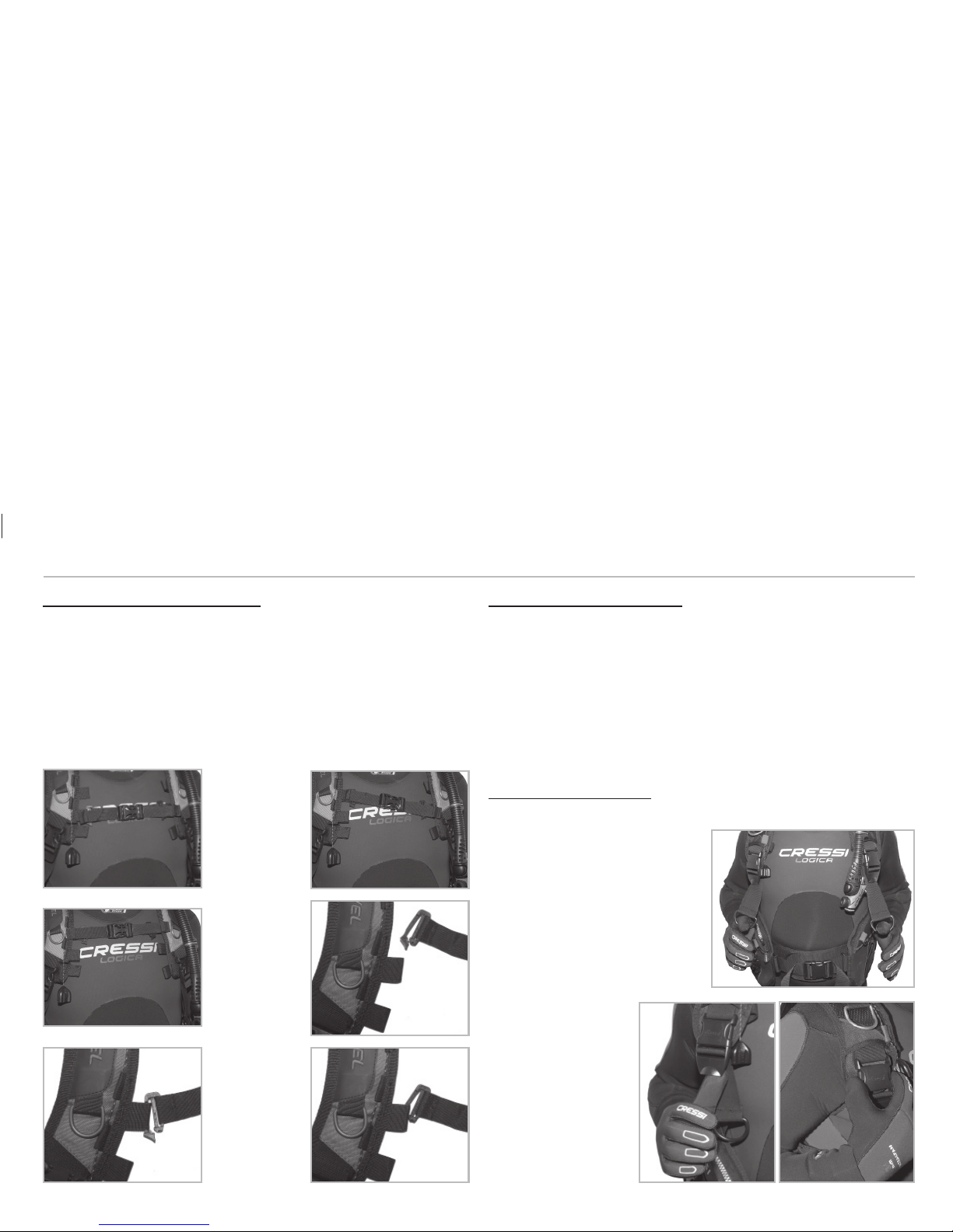
ADJUSTABLE WAIST BAND WITH BUCKLE
This type of waist band is very similar to the standard one; its distinctive
feature is that it can be adjusted also at the back, in the coupling point with
the backplate. It is put on like a standard waist band with buckle; howe-
ver, in order to adjust it, it is necessary to take off the BCD, remove the
backplate soft cover and open the Velcro strap that unites
the two ends (fig. 55 to 58). Below them, there are two belts coupled by
a quick-release buckle (fig. 59). Loosen or tighten the belts to the desi-
red length by using the buckle. Close back the two ends with Velcro (fig.
60) and place the backplate soft cover back in its place. Thanks to this
adjustment, the BCD can be adapted to different requirements, such as
having more comfort when wearing a waterproof wetsuit and the waist
bands are short.
(50) (51)
(52) (53)
(54)
(55) (56)
(57) (58)
English
32
BUCKLE
In the lightest and most compact BCD models, abdominal adjustment is
made by means of an adjustable quick-release buckle. Once the BCD has
been put on, close the buckle and tighten the belts to the desired length
(fig. 61 to 63).
STERNAL ADJUSTMENT
When wearing the BCD with regulator, the diver must withstand a conside-
rable weight. Most of it is distributed on the shoulders, causing discomfort.
The sternal coupling is used to distribute such weight to the thoracic area,
thus significantly relieving the stress on the shoulders.
In addition, while diving, it improves
comfort by helping the diver keep the
right tension in the shoulder straps
at all times. It consists in two straps
to be attached to the two shoulder
straps at the height of the sternum,
and which can be united and adju-
sted by means of a quick-release
buckle (fig. 64 to 66). For a correct
adjustment, put on the BCD and
immediately couple the coupling
buckle, tighten the shoulder straps
and close the BCD abdominal part.
Only at the end, tighten the two
adjustment straps so as to feel the
load relief on the shoulders. This
operation is easier if the cylinder is
rested somewhere or held by some-
body else. Finally, balance the ten-
sion on the shoulder straps with the
sternal adjustment tension so as to
obtain as much comfort as possible.
(59) (60)
(61) (62)
(63)
(66)
(65)
(64)
English
33
MOVABLE STERNAL ADJUSTMENT
In the movable sternal adjustment, the straps are attached to the shoulder
straps by means of buckles or tracks that enable its vertical movement
along the shoulder strap tag (fig. 67 to 69). In the first case, the buckles
must be opened and moved to the adjacent slot (fig. 70 to 72), while in
the second case, you just have to make the strap coupling slide along the
track. This adjustment enables to adapt the sternal coupling according to
the diver’s anatomy and equipment.
FIXED STERNAL ADJUSTMENT
In the fixed sternal adjustment, the coupling cannot be moved vertically; it
can only be adjusted horizontally by moving it closer to or away from the
shoulder straps.
SHOULDER STRAP ADJUSTMENT
The shoulder straps of a BCD have two quick-release buckles that can
be adjusted according to the diver’s physical condition, and completely
opened to take off the BCD.
STANDARD ADJUSTMENT
To adjust them, just take the two
“D” rings located at the ends and
pull with your arms downwards.
In this way, the shoulder strap will
tighten on your body. To loosen
it, use the buckle by putting one
finger under the lower part and
exerting force towards the out-
side of the chest and upwards. To
open it, press the buckle with two
fingers in the relative
tabs that will release the
male from the female
(fig. 73 to 75).
(71)
(69)
(67)
(72)
(70)
(68)
(73)
(74) (75)
English

34
LENGTH ADJUSTING SYSTEM (LAS)
Some BCD models enable the length adjustment of the shoulder straps ei-
ther by means of the buckles located at the front, near the tags, or by me-
ans of the rigid backplate to which the shoulder straps are attached. The
operation is very simple. Stretch out the BCD on a surface and remove
the top part of the backplate soft cover. Then, lift the padded bottom part
of the shoulder strap (fig. 76). Below such part, there is a strap connected
to the backplate loops by means of a buckle. Adjust the strap to lengthen
or shorten the shoulder strap (fig. 77 to 80). Once the desired length has
been reached, it is also necessary to adjust the buckle that connects the
shoulder strap to the top end of the air cell (fig. 81).
CONTROL UNIT
The control unit is the heart of all BCDs. The air charge and discharge
functions in the air cell are connected to such unit. It is made up of the By-
Pass, the Corrugated Hose and the Dump Valve (fig. 85). BY-PASS: The
By-Pass is the end part where all the charge and discharge push-buttons
and mechanisms are located (fig. 84). It must always be within the diver’s
grasp because it controls all the necessary operations in a BCD. The low
pressure whip coming from the 1st stage is connected to the By-Pass by
means of a quick coupling. This whip enables the By-Pass valve to blow
in the cylinder air. Such valve has been designed to be able to work with
a relative pressure ranging from 1 to 15 bars; however, it is recommended
to use it with a relative pressure of between 8 and 12 bars.
CAUTION: The low pressure whip must be screwed in the first stage of
the regulator by means of the suitable LP or MP (LOW-MEDIUM PRES-
SURE) low pressure outlet with 24 UNF 3/8” thread or 20 UNF ½” thread
using an adapter. The other outlets of the regulator are HP (HIGH PRES-
SURE), and they have a 20 UNF 7/16” female thread. NEVER connect the
BCD low pressure whip to the HP (HIGH PRESSURE) outlet, not even
with the aid of reducers. This would entail serious risks to personal safety.
CAUTION: It is recommended to replace the medium pressure whip in
the following cases:
- When there are air leaks from the rubber part or in the joints with the
metallic parts.
- When it shows anomalies while it is either pressurised or at rest. The
whip must always be perfectly cylindrical along its entire length.
- If it has a surface with alterations due to abrasion, rubbing or small cuts.
- If it has been subjected to any stress going beyond its regular use, such
as lifting the regulator or the fact that it remains entangled during abrupt
movements.
(76) (77)
(81)(80)(79)
(78)
English

35
- When it has been subjected to crushing or bumps, even if there are no
evident signs. There might be internal damage.
- When the nipple with the regulator is damaged.
CAUTION: It is recommended to replace the two gaskets of the whip
once a year.
To connect the whip to the by-pass, the end knurled bushing of the quick
coupling must be grasped and pulled backwards. At the same time,
completely insert the female coupling of the whip in the by-pass small
cylinder. Release the bushing and make sure the whip is correctly con-
nected by pulling it gently. To disconnect it, pull the bushing backwards
removing the whip from the by-pass (fig. 82-83).
CAUTION: Use only the original Cressi whips supplied. In case of repla-
cement, it is also recommended to use original Cressi whips.
CORRUGATED HOSE: The Corrugated Hose is the cylindrical rubber part
acting as a duct for air, as a guide for the cable that activates the dump
valve, and as housing for the whip (fig. 85).
DUMP VALVE: Finally, the quick dump valve is the end plastic part that is
connected to the air cell and which is in charge of emptying it by dischar-
ging the air (fig. 87).
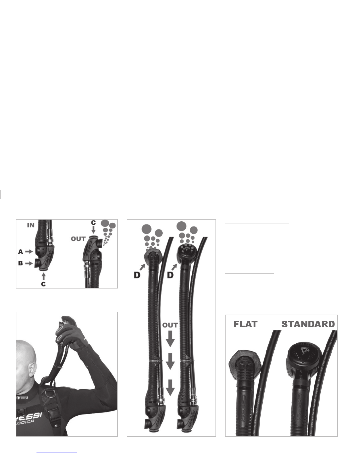
CONTROL UNIT FUNCTIONS:
So, as we have seen, by means of the control unit, a large number of
functions can be controlled. Such functions are listed below:
1 - Charging by means of push-button A (fig. 84). By pressing the push-
button, air is let in.
2 - Mouthpiece: Rest your mouth in slot B (fig. 84). Blow a small amount of
air to eliminate any residual water from the duct. Continue blowing while
fully pressing push-button C. As soon as push-button C is pressed, the air
will get into the cell. To interrupt it, release the push-button. Repeat the
operation if necessary.
3 - Discharge by means of D quick dump valve, which can be activated
by pulling the corrugated hose downwards (fig. 85). The diver’s position
must be vertical.
4 - Traditional discharge: with your body in vertical position, lift the corru-
gated hose towards the surface and press push-button C (fig. 86).
(82) (83)
English
36
STANDARD CONTROL UNIT
The distinctive feature of this control unit is that it has
a quick dump valve that can be manually activated
while also acting as an over-pressure valve at the
same time in case there is excessive pressure in the
air cell (fig. 87).
FLAT CONTROL UNIT
With respect to the standard model, the size and
weight of the quick dump valve are considerably lo-
wer. It is not fitted with over-pressure valve (fig. 87).
(84)
(86)
(85)
(87)
English
37
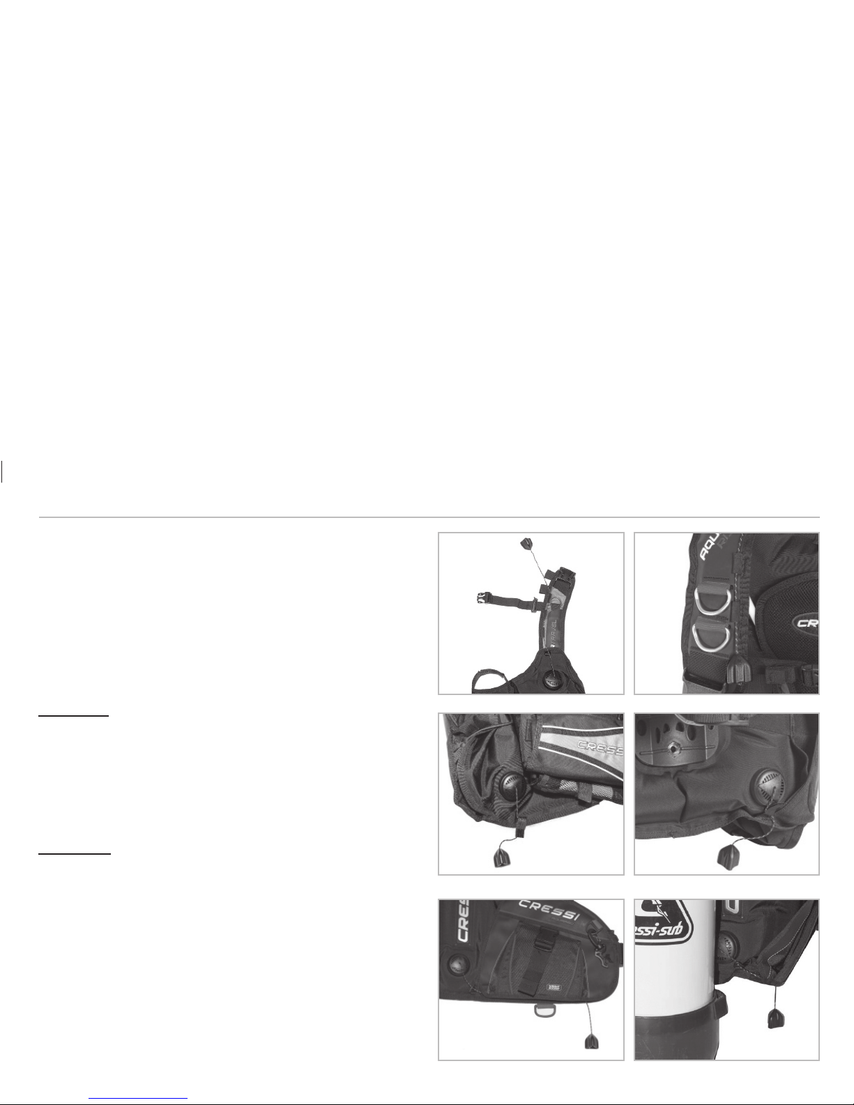
VALVES
In order to enable air release from the cell, all Cressi BCDs have a control
unit with two valves, as we have just seen, and two additional independent
quick dump and over-pressure valves. In this way, total safety is guaran-
teed to divers for managing immersion in emergency situations. These
last two valves are activated manually by pulling a knob, and they must be
easily accessible to enable the air cell emptying in most diver’s positions.
In addition, as it has been mentioned above, they are also over-pressure
valves, i.e. valves that let air go out of the cell when pressure is excessive.
LOW VALVE: It is located at the back, in the lower right external or lower
right internal area (in some BCDs with rear volume) and the knob to be
used for activating it can be located at the front under the accessory po-
cket or immediately under the valve itself, near the edge of the cell (fig.
90-91-92-93). It is used to discharge air when the diver has his/her head
down or is in horizontal position and, whenever necessary, at the end of
the diving activity, to discharge the water that has gotten into the cell.
HIGH VALVE: It is located in the upper right external area near the shoul-
der strap and its knob is located along the shoulder strap (fig. 88-89). It
is used to discharge air when the diver is in vertical position with his/her
head up.
(88)
(93)(92)
(91)(90)
(89)
English

38
FIXING HANGING PARTS OF
THE SCUBA:
There are some Scuba components that
have to be placed in the front part of the
body to facilitate their handling by the diver.
These are:
- The octopus emergency regulator or an al-
ternative source of air.
- The manometer or the console with the in-
tegrated instruments.
- Illuminators and emergency torches.
- Several whips.
- Emergency buoys.
- Knife.
- Swivels and reels.
- Other accessories.
Cressi has equipped its BCDs with suitable
pockets, “D” rings and clips, thanks to which
these components can be placed in a ratio-
nal and practical manner (fig. 94 to 98).
ACCESSORY POCKETS -
WEIGHT POCKETS
To put objects or equipment compo-
nents, Cressi BCDs have two handy
pockets on the sides (with Velcro or
zip closure) or, in the lightest and most
compact models, one single roll-up po-
cket with Velcro closure (fig. 99-100).
In the rear part, there may be two po-
ckets with zip or Velcro closure, which
are used to put equipment components
(such as the battery body of a torch) or
the ballast (fig. 101).
CAUTION: When the ballast is put
in these pockets, it is important to know
that in an emergency situation, such
ballast cannot be released, and that it
must be supplemented with a main bal-
last system. In addition, its weigh must
be reduced so that, by releasing the
main ballast, the diver is put in positive
buoyancy position.
(98)(97)
(96)
(95)
(94)
(101)
(100)
(99)
English

39
CHECKS BEFORE THE IMMERSION:
1 - Check the correct coupling of the low pressure whip.
2 - Make sure that the valves locking rings are properly tight.
3 - Make sure that the cylinder is perfectly secured.
4 - Inflate the BCD and check the air cell efficiency.
5 - Test the Control Unit functions several times.
5 - Check the activation of the over-pressure and quick dump valves.
WHILE DIVING:
Diving begins with a preparatory stop on the surface during which it is es-
sential to inflate the BCD. In this way, floating and swimming is facilitated
and the preliminary operations are safer. Once you are ready, to make the
descent, complete emptying will be necessary. During the descent it is
advisable to inflate the cell a little bit at a time so that your buoyancy is not
excessively negative and speed does not increase excessively. Once you
have reached the bottom position or the first stop position, inflate the cell
more until obtaining neutral buoyancy. This makes swimming easier. Be
very careful and do not go too far; it is preferable to keep slightly negative.
As a matter of fact, a deep breath or an upward fin bump could be enough
to change your buoyancy from neutral to positive and, if you are distracted,
this could put you in an extremely dangerous situation. This could genera-
te a very dangerous quick and uncontrolled ascent. To ward off such dan-
ger, you need to be very fast in understanding the buoyancy variation and,
consequently, discharge the BCD immediately by using the valves. Once
the time for remaining on the bottom has gone by, you have to ascend to
the surface thinking – first of all – about the air discharge, which must not
be complete but rather partial and proportional to the ascent position. In
a diver’s head, the ASCENT-BCD (and waterproof wetsuit) DEFLATION
action association must be indelibly marked. Deflation must be carried out
in such a way that the positive buoyancy that the BCD exerts in your body
is never felt. Once you reach the surface, inflate the BCD again.
PUTTING ON THE BCD:
The BCD is put on just like a regular gilet, making sure to put first the
arm having the instruments and then the other one, afterwards closing
the waist band Velcro closure and the belly buckle. While holding the he-
avy cylinder, it is advisable to place the BCD on an elevated surface with
respect to the ground so as to carry out this operation as comfortably as
possible. Make sure that the shoulder straps are wide enough to facilitate
this operation.
To put it on in the water, inflate it and sit on it with the fins facing the
bottom of the cylinder. Make your arms pass under the shoulder straps
and let yourself slide along the backplate towards the bottom. Close the
waist band, the belly buckle and the sternal coupling. Once you have put
it on, to adjust it, just pull the belts of the shoulder straps downwards, and
the sternal and belly belts towards the sides. In any case, for each single
adjustment, refer to the previous chapters.
EMERGENCY BCD REMOVAL:
In those situations in which the BCD has to be taken off quickly, just rele-
ase the buckle located in the belly area, open the waist band, and finally
release the sternal coupling and the quick-release buckles of the strap
shoulders. This operation can also be performed in normal situations,
mainly if you are a little bit uncomfortable.
English

40
As it has been said above in the “Control Unit” section, the inflation ope-
rations are performed by means of the by-pass push-button or with your
mouth through mouthpiece and push-button. It is advisable to have a lot
of practice with both methods, even if the use of the first one will be more
immediate and simpler. The diver’s position is not relevant for the purpose
of this operation. The deflation operations are carried out by means of the
control unit, by pulling it downwards or lifting it from its bottom towards the
surface and pressing the relative push-button, and by means of the quick
dump valves located at the back by pulling the specific knobs. During the
deflation operations, the diver’s position is very important for the purpose
of the manoeuvre. The diver shall be in vertical position with respect to the
surface to make the discharge with the control unit or the high rear valve.
Whereas in order to make the discharge through the low rear valve, the
diver must have his/her head down and, more precisely, the lower part of
the BCD upwards. When making the discharge, attention must be paid so
as to close the devices as soon as no more air comes out. Otherwise, the
water that is not obstructed by the air will start getting into the cell, altering
its floating capacity.
WARNINGS: In the rear volume BCD models, while being on the surfa-
ce, the air mass tends to position the diver horizontally with his/her down;
therefore, in case of loss of consciousness, the head remains immersed.
Therefore, they are to be used by expert divers who are perfectly aware
of their characteristics.
WARNINGS:
As pointed out in the previous section, an incorrect control of the BCD
may lead to extremely dangerous quick and uncontrolled ascents, which
almost always result in serious or mortal accidents due to decompression.
In order to prevent these situations, it is recommended – during ascents –
to release the air gradually from the BCD so as to always keep a slightly
negative buoyancy. If you are in vertical position, this operation is perfor-
med by activating the upper valves; whereas – less often – when the body
position is upturned with the head down, the low valve is used. In any
case, as a general rule, it is always valid the principle of
using the valve that is closer to the surface to release air.
English

41
LIMITS OF USE AND DURATION:
1 - The use of this BCD must be limited to the first 50 metres of depth.
2 - This BCD must be exclusively used with components of the SCUBA
diving regulator having CE marking.
3 - This BCD can be used in waters with temperature ranging from -2°C to
+40°C. The external (ambient) temperature range in which it can be used
is between –20°C and +50°C.
Immersions in extreme conditions with water temperature below 10°C are
risky for the human physiology; it is therefore necessary to have taken and
passed specific courses for such conditions.
4 - A BCD is not a lifejacket and, as such, it does not guarantee a head up
position of wearer.
5 - The BCD described in this manual must not be used alternating betwe-
en regulators loaded with Nitrox and regulators loaded with Air. It must
be exclusively used with only one type of gaseous mixture throughout its
entire service life.
6 - No change may be made to this BCD, not even minor changes. This is
forbidden for the sake of personal safety and health.
7 For the purpose of personal safety and health, it must not be used in pol-
luted waters or waters with high suspension, nor in any other liquid having
chemical-physical characteristics different from those of water.
8 - Using the BCD in chlorinated water damages the materials. Therefore,
it is advisable not to use it in water with high levels of chlorine.
MAINTENANCE:
For correct maintenance, it is important to follow the instructions given
below:
1 - Carry your BCD always inside a bag that protects it.
2 - Avoid contact with cutting or sharp objects, or objects that may cause
abrasions.
3 - Avoid long exposures to sunrays.
4 - At the end of each immersion into the Sea, Lake or Swimming Pool,
always rinse the BCD with fresh water both inside and outside. For the
inside, fill around 1/3 of the cell through the control mouthpiece (while ke-
eping the discharge push-button pressed down) and then inflate it partially
and shake it. Empty it by opening the lower quick dump valve.
5 - Every 4 or 5 immersions, clean and then lubricate the whip quick cou-
pling and the by-pass coupling with silicone grease.
6 - Replace the whip gaskets once a year in an authorised Cressi centre.
7 - It is recommended to have the BCD inspected once a year by an autho-
rised Cressi centre. In case of extensive use (diving centres, rental, pro-
fessional use or other), it is recommended to take the BCD to maintenance
every three/six months in an authorised Cressi centre.
8 - In case of whip replacement, the new one shall be of the same type
than the one supplied when the BCD was purchased. In case of doubts
regarding its characteristics, contact the manufacturer or the authorised
sales centre.
English
Table of contents
Other Cressi Diving Instrument manuals

Cressi
Cressi DESERT Manual

Cressi
Cressi CARTESIO User manual

Cressi
Cressi MC9 S.C. Manual

Cressi
Cressi EDY User manual

Cressi
Cressi Leonardo Manual

Cressi
Cressi SUB series User manual

Cressi
Cressi NEPTO User manual

Cressi
Cressi Scorpion Manual

Cressi
Cressi Bluetooth Interface User manual

Cressi
Cressi IZ750094 User manual

Cressi
Cressi AQUAWING Manual

Cressi
Cressi BT Interface User manual

Cressi
Cressi NEWTON Reference guide

Cressi
Cressi PORTER User manual

Cressi
Cressi CARTESIO User manual

Cressi
Cressi MC9 S.C. Manual

Cressi
Cressi Archimede II User manual

Cressi
Cressi Archimede User manual

Cressi
Cressi Leonardo Manual

Cressi
Cressi DIGI 2 User manual


