Shearwater Peregrine User manual

Operating Instructions

Operating Instructions
Page 2 Doc. 16001-SI-RevB (2020-07-06)
Table of Contents
Table of Contents��������������������������������������������������������������� 2
Conventions Used in this Manual����������������������������������������������������� 3
1. Introduction ................................................. 4
1�1� Notes on this manual������������������������������������������������������������������� 5
1�2� Modes Covered by this Manual������������������������������������������������ 5
2. Basic Operation ........................................... 6
2�1� Turning On ��������������������������������������������������������������������������������������� 6
2�2� Buttons�����������������������������������������������������������������������������������������������7
2�3� Button Hints �������������������������������������������������������������������������������������7
3. Mounting Options ........................................8
3�1� Silicone strap ���������������������������������������������������������������������������������� 8
3�2� Shock Cord �������������������������������������������������������������������������������������� 8
4. Dive Mode Interface.................................... 9
4�1� Default Dive Setup������������������������������������������������������������������������ 9
4�2� Dive Mode Differentiation���������������������������������������������������������� 9
4�3� Main Screen ������������������������������������������������������������������������������������10
4�4� Detailed Descriptions ������������������������������������������������������������������ 11
4�5� Info Screens������������������������������������������������������������������������������������14
4�6� Info Screen Descriptions ����������������������������������������������������������� 15
4�7� Notifications�����������������������������������������������������������������������������������18
4�8� Customizable Alerts�������������������������������������������������������������������� 21
4�9� List of primary notifications���������������������������������������������������� 22
5. Safety and Decompression Stops .......... 23
5�1� Safety Stops���������������������������������������������������������������������������������� 23
5�2� Decompression Stops ���������������������������������������������������������������24
6. Decompression and Gradient Factors ... 25
6�1� Decompression Information Accuracy �������������������������������26
7. Example Dives ........................................... 27
7�1� Single Gas Example Dive ��������������������������������������������������������� 27
7�2� Multi-Gas Example Dive������������������������������������������������������������ 28
7�3� Gauge Mode����������������������������������������������������������������������������������30
8. Menus ........................................................... 31
8�1� Menu Structure �����������������������������������������������������������������������������31
8�2� Turn off�������������������������������������������������������������������������������������������� 32
8�3� Select Gas (3 GasNx only)������������������������������������������������������� 32
8�4� Dive Setup ������������������������������������������������������������������������������������� 33
8�5� Dive Log������������������������������������������������������������������������������������������36
9. System Setup Reference.......................... 38
9�1� Mode Setup �����������������������������������������������������������������������������������38
9�2� Deco Setup������������������������������������������������������������������������������������39
9�3� Bottom Row ��������������������������������������������������������������������������������� 40
9�4� Nitrox Gases��������������������������������������������������������������������������������� 40
9�5� Alerts Setup ��������������������������������������������������������������������������������� 40
9�6� Display Setup������������������������������������������������������������������������������� 40
9�7� System Setup���������������������������������������������������������������������������������41
9�8� Advanced Config�������������������������������������������������������������������������42
10. Firmware Update and Log Download .... 44
10�1� Shearwater Cloud Desktop �����������������������������������������������������44
10�2�Shearwater Cloud Mobile���������������������������������������������������������46
11. Charging ..................................................... 47
12. Storage and Maintenance ........................ 48
13. Servicing..................................................... 48
14. Glossary ...................................................... 49
15. Peregrine Specifications.......................... 50
16. Regulatory Information............................. 51
17. Contact ........................................................ 51
Operating Instructions
Page 3 Doc. 16001-SI-RevB (2020-07-06)
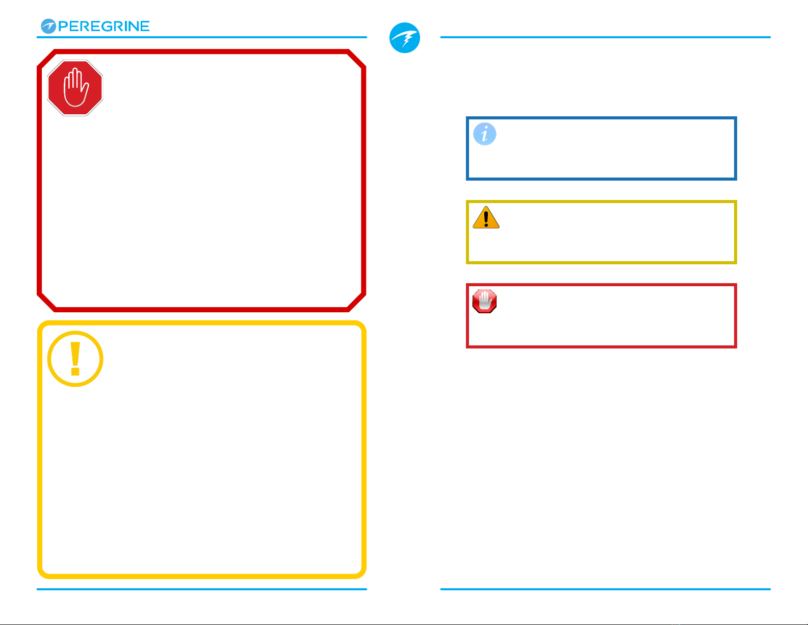
Conventions Used in this Manual
These conventions are used to highlight important
information:
INFORMATION
Information boxes contain useful tips for
getting the most out of your dive computer.
CAUTION
Caution boxes contain important instructions
for operating your dive computer.
WARNING
Warning boxes contain critical information
that may affect your personal safety.
This computer has bugs. Although we haven’t found them all yet,
they are there. It is certain that there are things that this computer
does that either we didn’t think about or planned for it to do
something different. Never risk your life on only one source of
information. Use a second computer or tables. If you choose to
make riskier dives, obtain the proper training and work up to them
slowly to gain experience.
This computer will fail. It is not whether it will fail but when it will
fail. Do not depend on it. Always have a plan for how to handle
failures. Automatic systems are no substitute for knowledge and
training.
No technology will keep you alive. Knowledge, skill, and practiced
procedures are your best defense (except for not doing the dive, of
course).
WARNING
This computer is capable of calculating decompression stop
requirements. These calculations are at best a guess of real physiological
decompression requirements. Dives requiring staged decompression
are substantially riskier than dives that stay well within no-stop limits.
Diving with rebreathers and/or diving mixed gases and/or performing
staged decompression dives and/or diving in overhead environments
greatly increases the risk associated with scuba diving.
YOU REALLY ARE RISKING YOUR LIFE
WITH THIS ACTIVITY.
DANGER

Operating Instructions
Page 4 Doc. 16001-SI-RevB (2020-07-06)
Features
• Full color 2.2” LCD display
• Rugged rubber bumper
• Rated to 120m / 390ft
• Air, Single-gas Nitrox, and multi-gas Nitrox modes
• Simplified recreational diving modes
• Full decompression support
• Bühlmann ZHL-16C with gradient factors
• No lockout for violating deco stops
• CNS tracking
• Quick No-deco limit (NDL) planner
• Full decompression planner
• Customizable vibration alerts
• Programmable depth sampling rates
• Bluetooth dive log uploading to Shearwater Cloud
• Wireless charging
• Firmware upgrades over Bluetooth
1. Introduction
The Shearwater Peregrine is a dive computer for
beginner to expert divers.
Please take the time to read this manual. Your safety
may depend on your ability to read and understand the
Peregrine displays.
Diving involves risk and education is your best tool for
managing this risk.
Do not use this manual as a substitute for proper dive
training and never dive beyond your training. What you
don’t know can hurt you.
Watch the video:
Peregrine Introduction
Operating Instructions
Page 5 Doc. 16001-SI-RevB (2020-07-06)
1.2. Modes Covered by this Manual
This manual provides operating instructions for all four dive modes
available in the Peregrine:
• Air
• Nitrox
• 3 GasNx
• Gauge
Some features of the Peregrine only apply to certain dive modes.
If not otherwise indicated, features described are applicable in all
dive modes.
Change the Dive Mode from the Mode Setup menu.
See details on page 38.
1.1. Notes on this manual
This manual contains cross-references between
sections to make it easier to navigate.
Underlined text indicates the presence of a link to
another section.
Do not change any settings on your Peregrine
without understanding the consequence of the
change. If you are unsure, consult the appropriate
section of the manual for reference.
This manual is not a substitute for proper training.
Firmware Version: V77
This manual corresponds to firmware version V77.
Feature changes may have been made since this
release and might not be documented here.
Check the release notes on Shearwater.com for a
complete list of changes since the last release.
Operating Instructions
Page 6 Doc. 16001-SI-RevB (2020-07-06)
2. Basic Operation
2.1. Turning On
To turn the Peregrine on, press both buttons together.
Auto-on
The Peregrine will automatically turn on when
submerged underwater. This is based on pressure
increase and not on the presence of water. When
auto-on is activated, the Peregrine will enter the last
configured dive mode.
Auto-on Details
The Peregrine turns on automatically when the
absolute pressure is greater than 1100 millibar (mbar).
For reference, normal sea level pressure is 1013 mbar
and 1 mbar of pressure corresponds to approximately
1 cm (0.4”) of water. So, when at sea level, the
Peregrine will automatically turn on and enter dive
mode when about 0.9 m (3 ft) underwater.
If at higher altitude, then the Peregrine auto-on will
occur at a deeper depth. For example, when at 2000
m (6500 ft) altitude the atmospheric pressure is
only about 800 mbar. Therefore, at this altitude the
Peregrine must be submerged underwater by 300
mbar to reach an absolute pressure of 1100 mbar.
This means the auto-on occurs at about 3 m (10 ft)
underwater when at an altitude of 2000 m.
Customizable Splash Screen
After turning on, the Peregrine Splash Screen is
displayed for 2 seconds.
Customizable start up text can be added using the
Shearwater Cloud Desktop app.
The image itself can also be customized using the
Shearwater Cloud Desktop App.
See the section on Connect to Shearwater Cloud
Desktop on page 44 for details.
Do Not Rely On The Auto-On Feature
This feature is supplied as a backup
for when you forget to turn on your
Peregrine.
Shearwater recommends turning your
computer on manually before each dive
to confirm proper operation and to
double check battery status and setup.

Operating Instructions
Page 7 Doc. 16001-SI-RevB (2020-07-06)
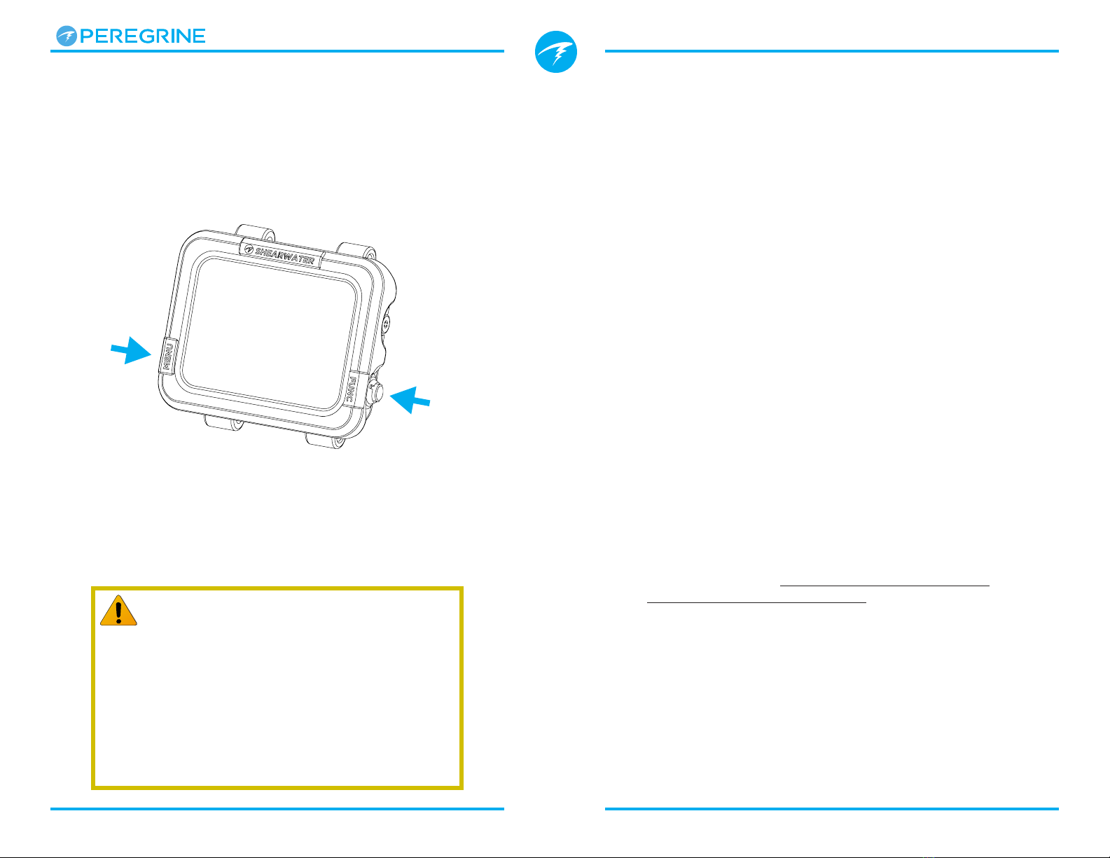
2.2. Buttons
Apart from turning on, all Peregrine operations are
simple single button presses.
Don’t worry about remembering all the button rules
below. Button hints make using the Peregrine easy.
MENU Button (Left)
• From the main screen >Cycles through menus.
• In a menu >Cycles through menus and options.
FUNC Button (Right)
• From the main screen >Cycles through info
screens
• In a menu >Selects menu or option
MENU
(Left)
FUNC
(Right)
Brightness
Change Save
MedBrightness
MENU hint FUNC hint
2.3. Button Hints
When in a menu, button hints indicate the function of each
button.

Operating Instructions
Page 8 Doc. 16001-SI-RevB (2020-07-06)
3. Mounting Options
The Peregrine is shipped with both a silicone strap and
shock cord. Before first use, you will need to install
your preferred mounting option.
3.1. Silicone strap
The included Peregrine strap is made of a durable,
stretchy silicone, designed to grip a wet suit or dry suit
without sliding around. Several strap colour options are
available (black is included).
The strap is fastened to the Peregrine via stainless steel
lugs which can be easily removed and replaced with
two standard Phillips screwdrivers (included). The lug
threads come with a pre-applied locking element that
performs best when tightened fewer than 5 times.
DO NOT OVER TORQUE LUG SCREWS
Once it feels tight, stop screwing. Over
torquing can damage screw threads.
3.2. Shock Cord
Shock cord or bungee can be installed in many ways on
the Peregrine. The Peregrine’s holes are sized for 4mm
cord.
The simplest option is to secure the shock cord is with
four simple overhand knots. However, this method
is not adjustable and a knot might pull through its
mounting hole at very high load.
Another method is to use slip knots. This provides
adjust ability when changing exposure protection.
Operating Instructions
Page 9 Doc. 16001-SI-RevB (2020-07-06)
4.2. Dive Mode Differentiation
Each dive mode is designed to best suit a particular
type of diving.
Air
Designed for use during recreational, air only,
no-decompression diving activities.
• Air (21% oxygen) only, not switchable underwater
• Simplified Info Rows
• Enhanced warnings
Nitrox (Single Gas)
Designed for use during recreational, Nitrox,
no-decompression diving activities.
• Single Gas Nitrox up to 40% oxygen
• No gas switching underwater
• Simplified Info Rows
• Enhanced warnings
3 GasNx (Three Gas Mode)
Designed for use during advanced diving activities
including light technical diving involving planned
decompression.
• Three programmable gases
• Support for gas switching
• Nitrox up to 100%
Gauge
Gauge Mode turns the Peregrine into a simple depth
and time display (a.k.a. a bottom timer). See page
30.
• No tissue tracking
• No decompression information
Change the Dive Mode from the Mode Setup menu.
See details on page 38.
4. Dive Mode Interface
4.1. Default Dive Setup
The Peregrine comes pre-configured for recreational
diving.
The default dive mode for the Peregrine is a simple
Air only mode.
As a quick reference, a diagram of the default diving
display is shown below.
Many attributes of this default mode are shared with
the other dive modes. The following sections go into
detail about each screen element.
See the Single Gas Example Dive on page 27 for a
walk through of how this screen changes through all
phases of a dive.
Ascent Rate
No-Deco
Limit
Dive Time
Active Gas
Single Gas Mode
3:00
Air 21
m
.o23°C
10:55am
MAX
.
7
:
:
Depth
Safety Stop
Nitrogen
Loading
Temperature
Time

Operating Instructions
Page 10 Doc. 16001-SI-RevB (2020-07-06)
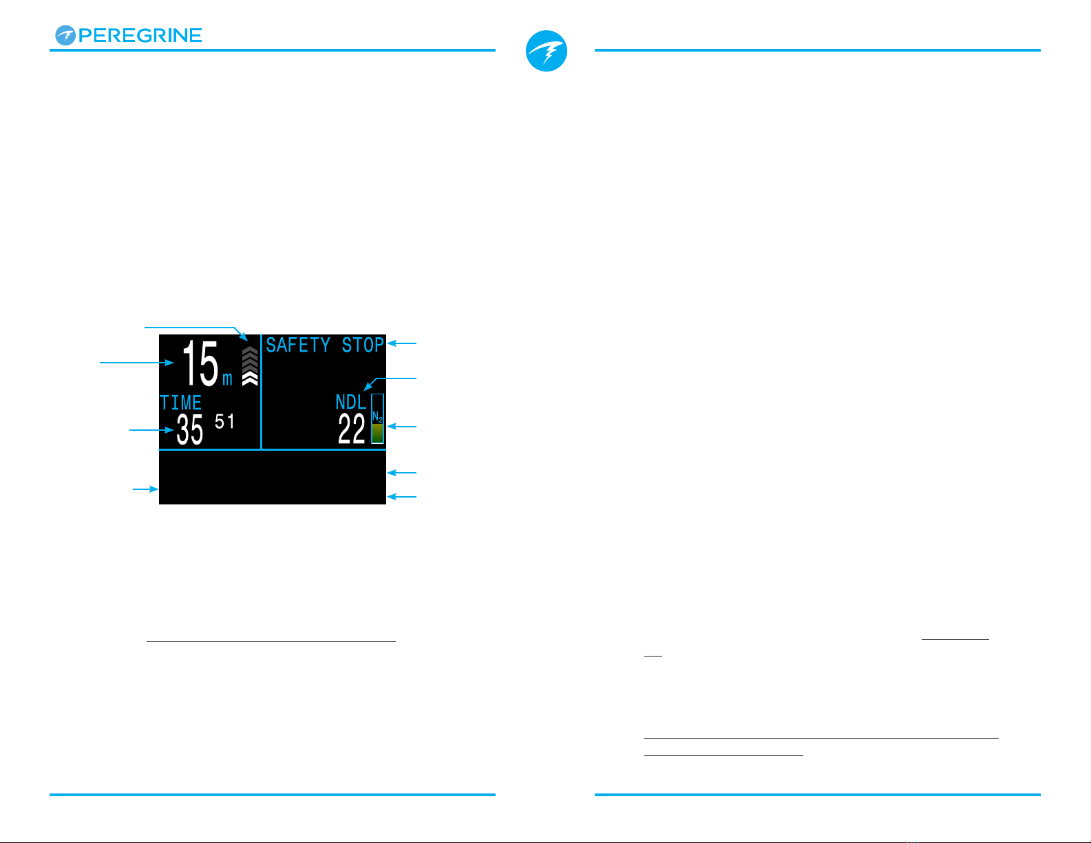
Basic Dive Info
The Basic Dive area shows:
• The current depth (in feet or meters)
• The dive time in minutes and seconds
When on the surface, the dive time is replaced by
a surface interval timer. Also, a battery gauge will
appear in this area.
Decompression Info
The Decompression area shows:
• Safety stops (if enabled)
• Decompression stops
• No-Decompression Limit (NDL) in minutes
• Nitrogen loading bar graph
• Warnings for Maximum Operating Depth (MOD) and
Central Nervous System oxygen toxicity (CNS)
Configurable Info Row
The bottom-left position on the home screen always
shows the currently selected gas.
The center and right positions can be configured
to display a variety of different information. By
default they show maximum depth, time of day and
temperature.
See “Configurable Info Row” on page 13 for
customization options.
Pressing the FUNC (right) button will cycle the Info
Row through additional data. Pressing the MENU (left)
button will return the info row to the home screen.
4.3. Main Screen
The Main Screen shows the most important
information for Air and Nitrox diving.
It is divided into three sections: Basic dive info,
decompression info, and the Info Row.
Basic Dive
Information
Depth, Time
& Ascent Rate
Decompression
Information
NDL, Safety Stops,
Deco Stops, Warnings
Info Row
Configurable
The Basic Dive Info section and the Decompression
Info section content are reserved for the most critical
information and are fixed. Pressing the FUNC (right)
button scrolls through additional data in the Info row.
3:00
Air 21
m
.o23°C
10:55am
MAX
.
7
:
:
Main Screen Sections

Operating Instructions
Page 11 Doc. 16001-SI-RevB (2020-07-06)
4.4. Detailed Descriptions
Basic Dive Info Area
The Basic Dive Info Area shows depth, dive time,
ascent rate, and state of battery charge (when at the
12
20
6
WHITE when less than 9 mpm / 30 fpm
(1 to 3 arrows)
YELLOW when greater than 9 mpm /
30 fpm and less than 18 mpm / 60 fpm
(4 or 5 arrows)
FLASHING RED when greater than
18 mpm / 60 fpm (6 arrows)
BLUE when battery charge is OK
YELLOW when battery needs to
be charged.
RED when battery must be
charged immediately.
3:00
Air 21
m
.o23°C
10:55am
MAX
.7
:
:
surface).
Depth
The depth is shown in the top
left. When in meters, one decimal
place is shown.
Note: If the depth shows a Flashing
Red zero or shows at depth at the
surface, then the depth sensor needs
service.
Dive Time
Dive time displays in minutes
and seconds. It begins and ends
counting automatically when you
dive.
Surface Interval
When on the surface, the dive
time is replaced by the surface
interval in hours and minutes.
Beyond 96 hours(4 days), it
displays in days.
Air 21
m
.o23°C
10:55am
MAX
:
ft
45
DECO STOP
6 2
m min
0
Ascent Rate Display
Shows how fast you are currently ascending graphically.
1 arrow per 3 meters per minute (mpm) or 10 feet per
minute (fpm) of ascent rate.
Depth in Meters
and Dive Time
Depth in Feet
and Dive Time
3:00
Air 21
m
.o23°C
10:55am
MAX
:
ft
0
SURFACE
22:15
h m
Surface interval
and battery
symbol
Note: Deco calculations assume 10mpm (33fpm)
ascent rate.
Battery Icon
The battery icon is shown on the surface but
disappears when diving. If low or critical then the
battery icon will appear while diving.
3:00
Air 21
m
.o23°C
10:55am
MAX
:
ft
0
SURFACE
22:15
h m
3:00
Air 21
m
.o23°C
10:55am
MAX
:
ft
0
SURFACE
22:15
h m
3:00
Air 21
m
.o23°C
10:55am
MAX
:
ft
0
SURFACE
22:15
h m
The surface interval resets
when decompression
tissues are cleared.

Operating Instructions
Page 12 Doc. 16001-SI-RevB (2020-07-06)
Nitrogen Loading Bar Graph
The nitrogen bar graph is
scaled such that it is full once
decompression stops will be
needed.
On ascent, it gives a
much better indication of
decompression stress and
the risk of decompression
sickness than NDL does.
On the surface, the Nitrogen
Loading Bar Graph shows the
residual nitrogen from the
previous dive.
Persistent Notifications
Persistent notifications are
displayed to the left of NDL.
If multiple warnings are
triggered, only the highest
priority will display.
Read more about
Notifications on page 18
for more information on
warnings.
Decompression Info Area
No Decompression Limit (NDL)
20
NDL
5
NDL
The time remaining, in minutes, at the
current depth until decompression stops
will be necessary.
Displays in Yellow when the NDL is less
than the low NDL limit (Default 5 minutes).
Important!
All decompression information including
Deco Stops, NDL, and Time to surface are
predictions that assume:
• Ascent rate of 10mpm / 33fpm
• Decompression stops will be followed
• All programmed gases will be used as
appropriate
Read more about Decompression and
Gradient Factors on page 25.
3:00
Air 21
m
.o23°C
10:55am
MAX
.7
:
:
Air 21
m
.o23°C
10:55am
MAX
:
ft
45
DECO STOP
6 2
m min
0
NDL > 0 minutes
Safety Stop
suggested
NDL = 0 minutes
Decompression
Stops Required
Safety Stop
Appears when a safety stop is
recommended and counts down
automatically when in the safety
stop range.
Safety stops may be turned off,
set to fixed times of 3, 4, or 5
minutes, set to adapt based on
dive conditions, or be set to
count up from zero.
See Safety Stops on page 23
for details.
Deco Stop Depth and Time
Once NDL = 0 minutes,
mandatory decompression is
required. The safety stop counter
will be replaced by the shallowest
depth to which you can ascend
and how long to hold that stop.
See Decompression Stops on
page 24 for details.
5:00
Air 21
m
.o23°C
10:55am
MAX
.7
:
:
3

Operating Instructions
Page 13 Doc. 16001-SI-RevB (2020-07-06)
Active Gas
The active gas position is not configurable. It always
shows the currently selected breathing gas.
Configurable Info Row
The Home Screen is the default display for the info
row. Information in the center and right positions can
be customized.
Configurable Center & Right Positions
Many possible configurations can be set for the center
and right positions of the bottom row.
Default Info row
5:00
Air 21
m
.o23°C
10:55am
MAX
.7
:
:
3
5:00
Air 21
m
.o23°C
10:55am
MAX
.7
:
:
3
5:00
Nx32 21
m
.o23°C
10:55am
MAX
.7
:
:
3
5:00
m
.o23°C
10:55am
MAX
.7
:
:
3
Nx32 21
Lorem ipsum
21% O2
32% O2
Better Gas
available
When air (21% O2) is used, the value “Air’
is displayed.
For all other gases, it displays “Nx”
(Nitrox) followed by the O2%.
The gas will display in yellow if a better
gas is available. (3 GasNx mode only)
The gas will display in flashing red if the
MOD of the gas has been exceeded.
5:00
m
.o23°C
10:55am
MAX
.7
:
:
3
Nx32 21
5:00
m
.o23°C
10:55am
MAX
.7
:
:
3
Nx32 21
Gas displayed in flashing red
when MOD has been exceeded
Option Info Display
TTS
PPO2
CNS %
MOD
GF99
Surf� GF
Δ+5
@+5
Option Info Display
Max Depth
Avg. Depth
Clock
Timer
Temperature
Ceiling
Dive End
Time
Rate
MODCNS
%
11
mmin
PPO2
.21271
SURFACE
MODCNS
%
11
mmin
PPO2
.21271
SURFACE
MODCNS
%
11
mmin
PPO2
.2157
SURFACE
mmin
GF
35/75
GF99
22
%
136
%
SurfGF
SURFACE
mmin
Δ+5
+8
@+5
20
CEIL
26
SURFACE
mmin
GF
35/75
GF99
22
%
136
%
SurfGF
SURFACE
125
14
T1
min
TTS
23
MAX AVG
13.3
m
31.6
m
mmin
SURFACE
MAX AVG
13.3
m
31.6
m
mmin
SURFACE
TIME
2:31
DET
2:43
mmin
SURFACE
TIME
2:31
DET
2:43
mmin
SURFACE
.0
0
ft
MAX
ft
103.6 4:57
TIMER
SURFACE
Deep
19:16
FD
TEMP
21 49
BATTERY
%
�C
mmin
SURFACE
m
0.0
T1 �+5
1753
T2
20450
DECO
mmin
TTS
OC Tec
SURFACE
mh
3412
18/45
---- -
3:00
Air
.
7
:
:
15 62
SurGF
GF99
% %
Bottom Row
Center GF99
SurGF
GF99
SurGF
15 62
% %
Change Save
All dive modes share the same home screen
customization.
See details for how to change the configuration of the
Bottom Row on page 40.
All bottom row options are listed below. Descriptions
of each function can be found in the next section
(INFO Screens)
.0
0
ft
MAX
ft
103.6 11
CEIL
SURFACE
Deep
19:16
FD
.0
0
ft
MAX
ft
103.6 10
RATE
SURFACE
Deep
19:16
FD
min
m
Operating Instructions
Page 14 Doc. 16001-SI-RevB (2020-07-06)
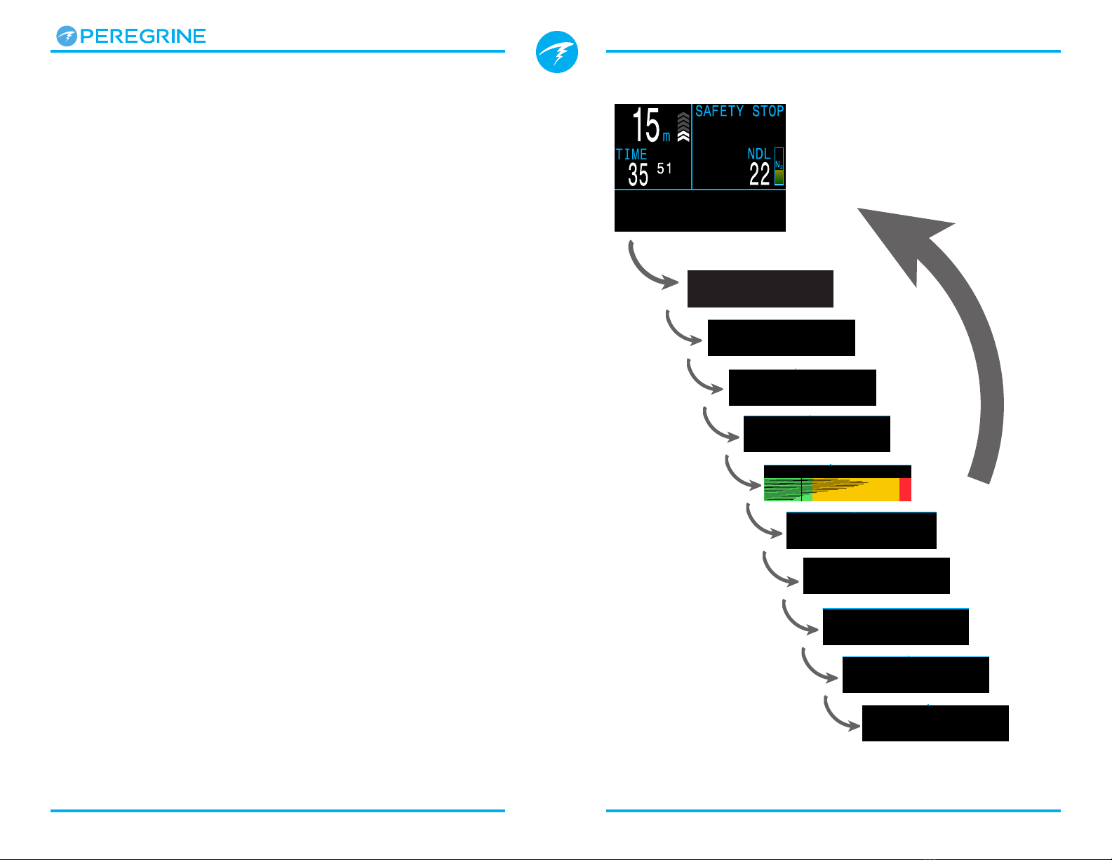
4.5. Info Screens
Info screens provide more information than is
available on the main screen.
From the main screen, the FUNC (right) button steps
through info screens.
When all info screens have been viewed, pressing
FUNC again will return to the main screen.
Pressing the MENU (left) button will also return to the
home screen at any time.
Info screens also automatically time-out after 10
seconds, returning to the home screen. This prevents
active gas information from being hidden for an
extended period.
Note that the Tissues Info screen does not
automatically time out. This allows tissue off-gassing
to be observed on an extended deco stop without
having to cycle back to it repeatedly.
Although these screens are generally representative
of the Peregrine display, info screen content varies for
each mode. For example, decompression related info
screens are not available in gauge mode.
3:00
12
52
00/ 0
Δ+5
.7
:
:
DET @+5/TTS
:
Press the FUNC button
(right), to step through
Info Screens
Return to Main Screen by:
•Pressing MENU button
•Stepping past last screen
•Waiting 10 Seconds (most screens)
3:00
Air 21
m
.o23°C
10:55am
MAX
.7
:
:
3:00
57 21 .54
m
.o
MAX
.7
:
:
MOD
m
PPO2
3:00
20 0
CONSERV
.7
:
:
TEMP
°C
CNS
Med
40/85
3:00
15 62 0
SurGF
.7
:
:
GF99
%
CEIL
%
3:00
.7
:
:
TISSUES
3:00
4
.
12V
3.7V
.7
:
:
LiIon
BATTERY
3:00
1020 1021
.7
:
:
PRESSURE mBar
SURF NOW
3:00
03-Mar-20 6 42
.7
:
:
DATE CLOCK
:
3:00
9F1F0432 20080BC
.7
:
:
SERIAL NO VERSION
SAFETY STOP
SURFACE
h
NDL
00
LAST DIVE
0
ft
N
2
m
01
105
#1234
MAX ft
0
h
52
m
38
s
Operating Instructions
Page 15 Doc. 16001-SI-RevB (2020-07-06)
Conservatism
The conservatism values for the
Bühlmann GF decompression
algorithm.
Read more about Decompression and Gradient
Factors on page 25.
CNS Toxicity Percentage
Central Nervous System oxygen
toxicity loading percentage (CNS).
Turns Yellow when greater than
90%. Turns Red when greater than
150%.
The CNS percentage is calculated
continuously, even when the dive
computer is on the surface and
turned off. When deco tissues are
reset, the CNS will also be reset.
The CNS value (short for Central Nervous System
Oxygen Toxicity) is a measure of how long you have
been exposed to elevated partial pressures of oxygen
(PPO2) as a percentage of a maximum allowable
exposure. As PPO2 goes up, the maximum allowable
exposure time goes down. The table we use is from
the NOAA Diving Manual (Fourth Edition). The
computer linearly interpolates between these points
and extrapolates beyond them when necessary.
Above a PPO2 of 1.65 ATA, the CNS rate increases at a
fixed rate of 1% every 4 seconds.
During a dive the CNS never decreases. When back at
the surface, a half-life of elimination of 90 minutes is
used.
For example, if at the end of the dive the CNS was
80%, then 90 minutes later it will be 40%. In 90 more
minutes it will be 20%, etc. Typically, after about 6
half-life times (9 hours), everything has returned close
to equilibrium (0%).
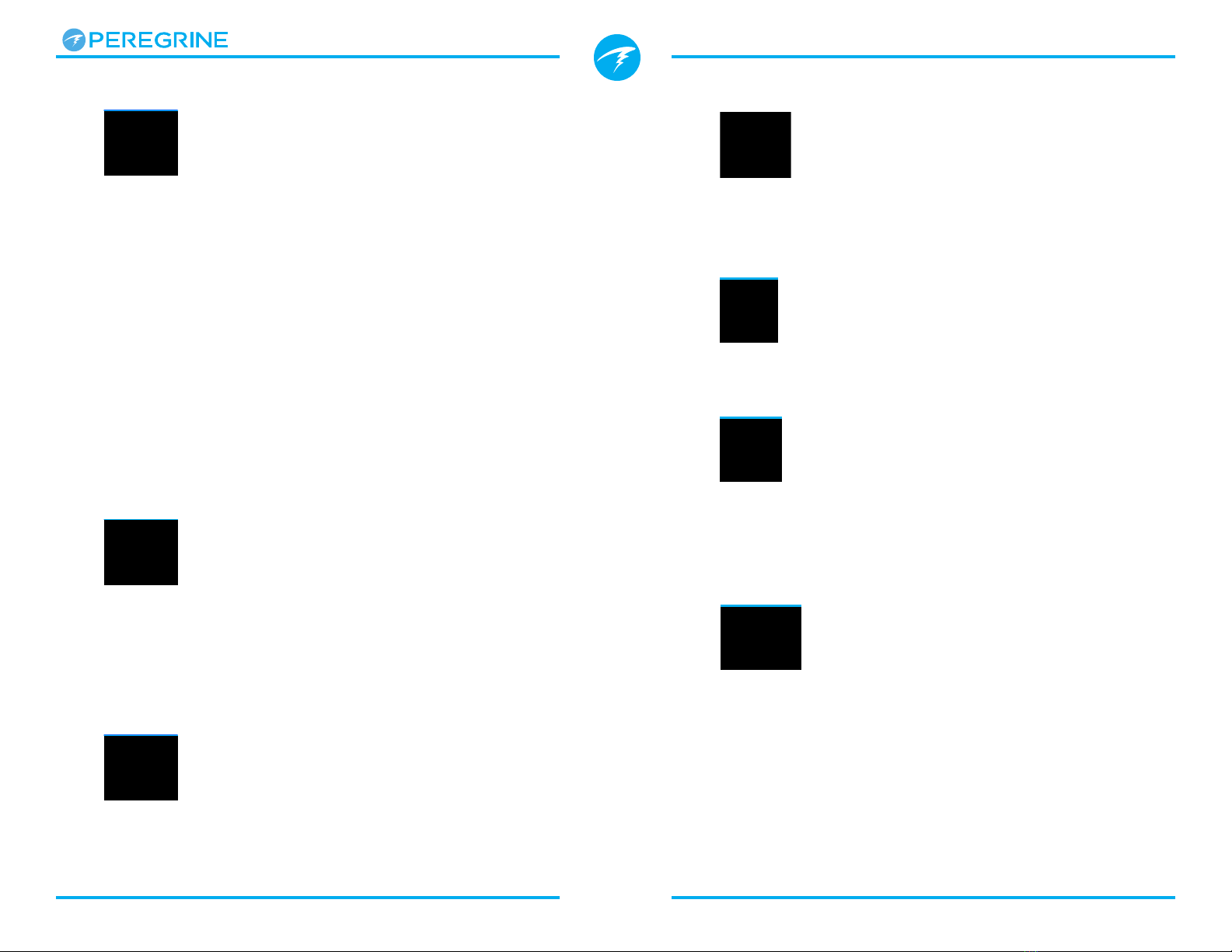
4.6. Info Screen Descriptions
Last Dive Info Screen
Maximum depth and dive time from the last dive. Only
available at the surface.
Maximum Operating Depth
MOD is the maximum allowable
depth of the current breathing gas
as determined by PPO2 limits.
Displays in Flashing Red when
exceeded.
Maximum Depth
The maximum depth of the current
dive. When not diving, displays the
maximum depth of the last dive
Partial Pressure of Oxygen (PPO2)
PPO2 of the current breathing gas.
Displays in Flashing Red when
outside customizable PPO2 limits.
Read more about PPO2 Limits on
page 43.
Temperature
The current temperature in degrees
Celsius or degrees Fahrenheit.
Temperature units can be set in the
Display settings menu.
3:00
57 21 .54
m
.o
MAX
.7
:
:
MOD
m
PPO2
3:00
57 21 .54
m
.o
MAX
.7
:
:
MOD
m
PPO2
3:00
57 21 .54
m
.o
MAX
.7
:
:
MOD
m
PPO2
3:00
20 0
CONSERV
.7
:
:
TEMP
°C
CNS
Med
40/85
3:00
20 0
CONSERV
.7
:
:
TEMP
°C
CNS
Med
40/85
MODCNS
%
11
mmin
PPO2
.21271
SURFACE
MODCNS
%
101
mmin
PPO2
.21271
SURFACE
SAFETY STOP
SURFACE
h
NDL
00
LAST DIVE
0
ft
N
2
m
01
105
#1234
MAX ft
0
h
52
m
38
s
3:00
57 21 .54
m
.o
MAX
.7
:
:
MOD
m
PPO2
Operating Instructions
Page 16 Doc. 16001-SI-RevB (2020-07-06)
GF99
The current gradient factor as
a percentage of the controlling
compartment m-value (i.e. super-
saturation percent gradient)
0% means the leading tissue super-saturation is equal
to ambient pressure. Displays “On Gas” when tissue
tension is less than the inspired inert gas pressure.
100% means the leading tissue super-saturation is
equal to the original M-Value limit in the Bühlmann
ZHL-16C model.
GF99 is displayed in Yellow when the current gradient
factor modified M-Value (GF High) is exceeded.
GF99 is displayed in Red when 100% (un-modified
M-Value) is exceeded.
Surface GF
The surfacing gradient
factor expected if the diver
instantaneously surfaced.
SurGF colour is based on the current GF (GF99). If
the current GF is greater than GF High, SurGF will be
displayed in Yellow. If the current gradient factor is
greater than 100%, SurGF will be displayed in Red.
Ceiling
The current decompression ceiling
not rounded to the next deeper
stop increment. (i.e. not a multiple
of 10ft or 3m)
3:00
15 62 0
SurGF
.7
:
:
GF99
%
CEIL
%
3:00
15 62 0
SurGF
.7
:
:
GF99
%
CEIL
%
3:00
15 62 0
SurGF
.7
:
:
GF99
%
CEIL
%
Time To Surface
The Time-To-Surface (TTS) in
minutes. This is the current time to
ascend to the surface including the
ascent plus all required deco stops
and safety stops.
@+5
“At plus 5” is the TTS if remaining
at the current depth for 5 more
minutes. This can be used as a
measure of how fast you are on-
gassing or off-gassing.
Δ+5
The predicted change in TTS if you
were to stay at the current depth
for 5 more minutes.
A positive “Delta plus 5” indicates that you are on-
gassing the leading tissue while a negative number
indicates that you are off-gassing the leading tissue.
Dive End Time (DET)
The time of day at which you
can expect to surface if you
depart immediately, ascend at
10mpm or 33fpm, change gases
when prompted, and perform all
decompression stops as directed.
3:00
12
52
00/ 0
Δ+5
.7
:
:
DET @+5/TTS
:
3:00
12
52
00/ 0
Δ+5
.7
:
:
DET @+5/TTS
:
3:00
12
52
00/ 0
Δ+5
.7
:
:
DET @+5/TTS
:
125
14
T1
min
TTS
23
Operating Instructions
Page 17 Doc. 16001-SI-RevB (2020-07-06)
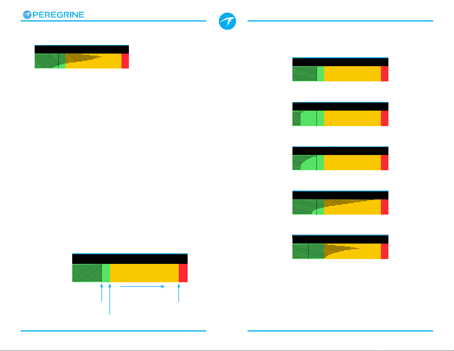
Sample Tissue Bar GraphsTissues Bar Graph
The tissues bar graph shows the tissue compartment
inert gas tissue tensions based on the Bühlmann ZHL-
16C model.
Each bar represents the nitrogen inert gas tension for
one compartment. The fastest tissue compartment
is shown on the top, and the slowest on the bottom.
Pressure increases to the right.
The vertical black line shows the inspired partial
pressure of nitrogen. The green-yellow interface line is
the ambient pressure. The yellow-red interface line is
the ZHL-16C M-Value pressure.
Tissues that are supersaturated above ambient
pressure extend into the yellow, and tissues that are
supersaturated above the M-Value extend into the red.
Note that the scale for each tissue compartment is
different. The reason the bars are scaled in this way is
so that the tissues tensions can be visualized in terms
of risk (i.e. how close they are as a percentage to
Bühlmann’s original super-saturation limits). Also, this
scale changes with depth, since the M-Value line also
changes with depth.
Inspired inert
gas pressure
Ambient
Pressure
Increasing
Pressure
M-Value
Pressure
16 tissue
compartments
{
On surface (sat. with air)
Note: Gas is 79% N2 (21% O2, or Air)
Immediately after descent
Deepest Stop
On Gassing
Last deco Stop
Note: Gas is now 50% O2and 50% N2
mmin
SURFACE
TISSUES
3:00
.7
:
:
TISSUES
3:00
.7
:
:
TISSUES
3:00
.7
:
:
TISSUES
3:00
.7
:
:
TISSUES
3:00
.7
:
:
TISSUES
3:00
.7
:
:
TISSUES
3:00
.7
:
:
TISSUES

Operating Instructions
Page 18 Doc. 16001-SI-RevB (2020-07-06)
Pressure
The pressure in millibar. Two values are shown,
the surface (surf) pressure and the current (now)
pressure.
Note that typical pressure at sea level is 1013 millibar,
although it may vary with the weather (barometric
pressure). For example, in a low pressure system
surface pressure may be as low as 980 millibar, or as
high as 1040 millibar in a high pressure system.
For this reason, the PPO2 displayed on the surface
may not exactly match the FO2 (fraction of O2),
although the displayed PPO2 is still correct.
The surface pressure is set based on the lowest
pressure the Peregrine sees in the 10 minutes prior to
computer turn on. Therefore, altitude is automatically
accounted for and no special altitude setting is
required.
Battery
Current voltage of the internal
battery. Displays in yellow when
battery is low and needs to be
recharged. Displays in red when
battery is critically low and must be
recharged immediately.
Clock
In a 12 or 24 hour format. Time
format can be changed in the watch
settings menu.
Date
In the format Day-Month Year.
3:00
1020 1021
.7
:
:
PRESSURE mBar
SURF NOW
3:00
03-Mar-20 6 42
.7
:
:
DATE CLOCK
:
3:00
03-Mar-20 6 42
.7
:
:
DATE CLOCK
:
3:00
4
.
12V
3.7V
.7
:
:
LiIon
BATTERY
4.7. Notifications
This section describes the different types of
notifications the computer may present the diver.
See the List of primary notifications on page 22
that a diver may encounter.
Color Coding
Color coding of text draws attention to problems or
unsafe situations.
WHITE text indicates normal conditions by default.
Note that this normal condition color can be selected
in the advanced configuration menu, described on
page 42.
YELLOW is used for warnings
that are not immediately
dangerous but should be
addressed.
FLASHING RED is used for
critical warnings that could
be life threatening if not
immediately addressed.
Warning
Flashes
The warning or critical warning states can
be determined without the use of color.
Color blind users
Warnings display
on a solid inverted
background.
Critical Warnings flash
between inverted and
normal text.
Doesn't flash
NX32
PPO2 PPO2
1.49 1.49
Sample warning -
a better gas is available
NX32
PPO2 PPO2
1.49 1.49
Sample critical warning -
Continuing to breathe this gas could
be fatal
Warning Warning

Operating Instructions
Page 19 Doc. 16001-SI-RevB (2020-07-06)
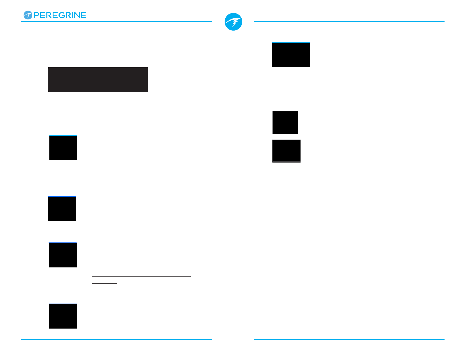
Types of Notifications
Primary Notifications
Each of the primary notifications will display as
a message in yellow across the bottom row until
dismissed.
5:00
.2
:
:
37
11
HIGH PPO2
Warning
Confirm
The notification is dismissed by pressing either button.
For example, this “HIGH PPO2” message will appear if
the average PPO2 goes above the PPO2 limit for more
than 30 seconds.
The highest priority notification is listed first. If multiple
errors occur simultaneously, the notification with
the highest priority will be displayed. Clear the first
notification by pressing a button to see the next one.
If vibration alerts are on, the unit will vibrate when
the alert first occurs and every 10 seconds until it is
acknowledged.
A list of primary notifications a diver may see is given
on page 22.
5:00
Nx32
.2
:
:
1.49 62
SurGF
PPO2
%
37
11
Sample Primary notification -
High PPO2 Warning
Sample Persistent Notification -
MOD Exceeded
Persistent Notifications
When the computer detects
a dangerous situation, such
as high PPO2, a warning is
triggered. The large primary
notification can be dismissed,
but in most cases, a persistent
notification will remain on the
screen to the left of the NDL
until the condition that caused
the warning is resolved.
List of Persistent Notifications
High CNSHigh CNS
Central Nervous System (CNS)
Oxygen Toxicity limit reached.
MOD, go upMOD, go up
Maximum Operating Depth
(MOD) exceeded. Ascend to
shown depth.
MOD, switch gasMOD, switch gas
Maximum Operating Depth
(MOD) exceeded. Switch to
more appropriate gas (another
gas must be programmed and
turned on for this to appear).
Near MODNear MOD
Within 5ft (1.9m) below MOD.
Just a notification, no action
required.
Better GasBetter Gas
Another gas is programmed
that is more suitable at the
current depth. Only displays
when deco stops are needed.
Operating Instructions
Page 20 Doc. 16001-SI-RevB (2020-07-06)
Limitations of Alarms
All alarm systems share common weaknesses.
They can alarm when no error condition exists
(false positive). Or they can fail to alarm when
a real error condition occurs (false negative).
Respond to alarms if you see them, but
NEVER depend on them. Your judgment,
education, and experience are your best
defenses. Have a plan for failures, build
experience slowly, and dive within your
experience.
If you do not like vibrating alerts,
they are easily silenced.
Vibration Alerts
In addition to visual notifications, the Peregrine has
vibration alerts to help quickly notify the diver of
warnings, errors and dive events.
If turned on, attention vibration alerts occur when
a safety stop starts, pauses, or is completed.
Vibration alerts will also occur any time a primary
notification is triggered and every 10 seconds until it is
acknowledged.
The vibration alert settings can be changed in the
System Setup menu as described in Alerts Setup on
page 40, or in the Dive Setup menu described on
page 36.
It’s important the diver is aware of what type of
notification they can expect on a dive.
A Test Vibration tool is also available in the Dive Setup
menu and should be used regularly before diving to
ensure the vibrator is functioning properly.
Caution
Although vibration alerts are very useful,
never rely on them for your safety.
Electromechanical devices can and will
eventually fail.
Always be proactively aware of your depth,
no-decompression limit, gas supply, and
other critical dive data. You are ultimately
responsible for your own safety.
Table of contents
Other Shearwater Diving Instrument manuals

Shearwater
Shearwater Perdix Instruction Manual

Shearwater
Shearwater DCIEM User manual

Shearwater
Shearwater NERD 2 User manual

Shearwater
Shearwater DiveCAN Petrel 1 User manual

Shearwater
Shearwater Petrel Standalone User manual

Shearwater
Shearwater Perdix 2 User manual

Shearwater
Shearwater Petrel 3 User manual

Shearwater
Shearwater Perdix User manual

Shearwater
Shearwater Perdix User manual

Shearwater
Shearwater Petrel 2 How to use


