DIVIGRAPH VP2000 Series User manual

EVR-VPXDOC-0036
DIVIGRAPH
Rev 2.4.1
September 2021
Proprietary & Confidential – Copyright © 2020 Divigraph (Pty) Ltd. All Rights Reserved
VP Series 2000 User Guide

EVR-VPXDOC-0036 VP Series 2000 User Guide
DIVIGRAPH
Rev 2.4.1
September 2021
Proprietary & Confidential – Copyright © 2020 Divigraph (Pty) Ltd. All Rights Reserved ii
Copyright 2020 Divigraph (Pty) Ltd
All Rights Reserved
The information contained in this document is the property of Divigraph and its affiliates; and is subject
to change without prior notice. It is being supplied as a service to our customers and may not be altered
or its content repackaged without the express written consent of Divigraph.
Contact Information
When it is not possible to contact your local representative, use the following contact information:
Address
28 Prosperity Park, Computer Road,
Milnerton, Cape Town, 7441, RSA
Telephone
+27 (21) 065-0344
Email
support@divigraph.com
Internet
www.divigraph.com

EVR-VPXDOC-0036 VP Series 2000 User Guide
DIVIGRAPH
Rev 2.4.1
September 2021
Proprietary & Confidential – Copyright © 2020 Divigraph (Pty) Ltd. All Rights Reserved iii
Contents
General Safety......................................................................................................................................... 2
Receiving Inspection............................................................................................................................2
Handling and Storing Considerations ...................................................................................................2
Personal Safety Warnings .................................................................................................................... 2
Safe Disposal .......................................................................................................................................4
Hardware ................................................................................................................................................ 5
Intended Use....................................................................................................................................... 5
Compliance Information ......................................................................................................................5
Informations de conformité................................................................................................................. 5
Description .......................................................................................................................................... 6
System Components Required.............................................................................................................7
VP Series 2000 Components ................................................................................................................7
Network Requirements........................................................................................................................8
Network Design....................................................................................................................................... 9
Setup Overview ................................................................................................................................... 9
Consider Sensor Range ........................................................................................................................9
Consider Battery Life ......................................................................................................................... 10
Choose Network Topology................................................................................................................. 10
Plan Device Placement....................................................................................................................... 11
Installation and Configuration ............................................................................................................... 13
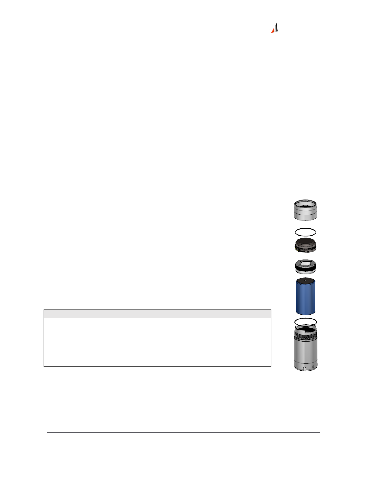
Install Battery .................................................................................................................................... 13
Configure Network ............................................................................................................................ 16
VP Series 2000 Configuration Software.............................................................................................. 16
Provision Devices............................................................................................................................... 16
Reboot the Device ............................................................................................................................. 24
Configure Devices.............................................................................................................................. 25
System 1 Installation and Configuration............................................................................................. 29
Mount Devices .................................................................................................................................. 30
Verification............................................................................................................................................ 33
Verify Network Connectivity.............................................................................................................. 33
Validate Device Data.......................................................................................................................... 35
Modbus Settings................................................................................................................................ 38

EVR-VPXDOC-0036 VP Series 2000 User Guide
DIVIGRAPH
Rev 2.4.1
September 2021
Proprietary & Confidential – Copyright © 2020 Divigraph (Pty) Ltd. All Rights Reserved iv
Maintenance ......................................................................................................................................... 40
Monitor Battery Levels ...................................................................................................................... 40
Battery Status Monitoring ................................................................................................................. 40
Clean and Inspect Devices.................................................................................................................. 42
Update Device Firmware ................................................................................................................... 47
Update Radio Firmware..................................................................................................................... 53
Troubleshooting VP Series 2000 Devices............................................................................................ 54
Harden the System ............................................................................................................................ 54

EVR-VPXDOC-0036 VP Series 2000 User Guide
DIVIGRAPH
Rev 2.4.1
September 2021
Proprietary & Confidential – Copyright © 2020 Divigraph (Pty) Ltd. All Rights Reserved 2
General Safety
Receiving Inspection
Visually inspect the product for obvious shipping damage. If you detect shipping damage, file a claim
with the carrier and submit a copy to Divigraph. Include all model numbers and serial numbers with the
claim.
Handling and Storing Considerations
Proper handling of components, best practices for system installation, and diligent inspection
procedures for the system will prolong the service life of the system. Additionally, procedures for
dealing with system components replaced by maintenance are detailed to allow compliance with
regulations relating to electronic waste.
Personal Safety Warnings
Labels and markings are provided to guide the system integrator in the processes of choosing
appropriate interface equipment, determining safe use conditions, and identifying recommended
installation procedures. The format of these markings are governed by the standards that dictate safe
use and environmental compliance in a variety of regions and regulated settings. More specific product
safety warnings are described in VP Series Warnings, Special Conditions and Additional Information
(DSDVP001).
Potential Electrostatic Charging Hazard
! WARNING
ELECTROSTATIC CHARGING HAZARD
RISK OF PERSONAL INJURY OR EQUIPMENT DAMAGE.
Potential for electrostatic charging hazard.
•Electrostatic discharge could cause a spark enough to ignite an explosion. In addition, electrostatic
discharge could damage to the product.
•Use extra caution during dry weather. Relative humidity less than 30% tends to multiply the
accumulation of static charges on any surface

EVR-VPXDOC-0036 VP Series 2000 User Guide
DIVIGRAPH
Rev 2.4.1
September 2021
Proprietary & Confidential – Copyright © 2020 Divigraph (Pty) Ltd. All Rights Reserved 3
Hazardous Environment
! WARNING
HAZARDOUS ENVIRONMENT
RISK OF EXPLOSIVE ATMOSPHERE.
Take precautionary measures to avoid electrostatic potential, especially on plastic
components.
Installations and maintenance tasks performed in potentially hazardous areas must be performed only
after the area has been verified to be free of hazardous materials, atmospheres, and conditions.
The following situations could cause a spark enough to ignite an explosion:
•Potential of electrostatic discharge on plastic components, or
•Removal or placement of an energized connection.
Lithium Batteries
! WARNING
LITHIUM BATTERIES
Do not use a device with a damaged battery. Using a damaged battery may
further damage the device, cause it to fail, or in hazardous locations cause other
unintended consequences.
Lithium batteries are volatile. When handling and storing lithium metal batteries, follow these
precautions:
•Store and handle lithium metal batteries to avoid contact with other lithium batteries.
•Do not place lithium metal batteries on metal work surfaces.
•Avoid exposing lithium metal batteries to extreme temperatures.
•If you store an inactive VP Series 2000 device, remove the battery.
•Dispose of used or defective batteries in accordance with the applicable statutes and regulations, as
well as site-specific safety requirements.
Lithium batteries typically last up to five years. Use the VP Series 2000 configuration software or
network vendor application to monitor battery performance and replace batteries as needed.

EVR-VPXDOC-0036 VP Series 2000 User Guide
DIVIGRAPH
Rev 2.4.1
September 2021
Proprietary & Confidential – Copyright © 2020 Divigraph (Pty) Ltd. All Rights Reserved 4
Safe Disposal
Replacing Device and Failure Analysis
Contact Divigraph for information on returning parts under warranty and/or requesting failure analysis.
Hazardous Materials
This device does not use hazardous materials outlined by RoHS or battery directive statutes. These
regulations confirm that lead, mercury, cadmium, hexavalent chromium, polybrominated biphenyls,
polybrominated diphenyl ether, and battery related materials such as lithium are limited to no more
than trace amounts within the system.
Recycling Facilities
Decommissioning of instrumentation should endeavor to minimize the impact of the waste created by
disposal of system material. Refer to local or regional waste removal administration to collect
information on proper material collection, reuse, and recycling.
Product Disposal Statement
Customers or third parties who are not member states of the European Union and who are in control of
the product at the end of its life or at the end of its use, are solely responsible for diligent product
disposal at the end of its useful life. No person, firm, corporation, association, or agency shall dispose of
the product in a way that is in violation of any applicable international, federal, state, or local
regulations. Divigraph is not responsible for product disposal at the end of its useful life. Visit
www.weeerohsinfo.com for recycling information.

EVR-VPXDOC-0036 VP Series 2000 User Guide
DIVIGRAPH
Rev 2.4.1
September 2021
Proprietary & Confidential – Copyright © 2020 Divigraph (Pty) Ltd. All Rights Reserved 5
Hardware
Intended Use
VP Series 2000 devices are intended for monitoring purposes only and should not be used in control or
safety systems.
Compliance Information
This device complies with part 15 of the FCC Rules and contains license-exempt
transmitter(s)/receiver(s) that comply with Innovation, Science and Economic Development Canada's
license-exempt RSS(s). Operation is subject to the following conditions: l
•This device may not cause harmful interference.
•This device must accept any interference received, including interference that may cause undesired
operation.
Changes or modifications not approved by the responsible party could void the user's authority to
operate the equipment.
For complete compliance and hazardous location approval information, see the VP Series2000
Datasheet (20DD1974) and VP Series Warnings, Special Conditions and Additional Information
(DSDVP001) available from Divigraph.
Informations de conformité
Cet appareil est conforme aux dispositions de la section 15 des règles de la FCC et contient des
émetteurs / récepteurs exempts de licence conformes aux CNR d’Innovation, Sciences et
Développement économique du Canada (ISDE Canada) applicables aux appareils radio exempts de
licence.
•Cet appareil ne doit pas produire de brouillage, et
•Cet appareil doit tolérer tout type de brouillage subi, y compris ceux susceptibles de perturber le
fonctionnement normal de l’appareil.
Les changements ou modifications non expressément approuvés par la partie responsable de la
conformité pourrait annuler le droit accordé à l'utilisateur d’exploiter cet équipement.
Pour obtenir des informations complementaires à propos de la conformité et de l'approbation de cet
appareil en zone dangereuse, veuillez consultez VP Series2000 Datasheet (20DD1974) et VP Series
Warnings, Special Conditions and Additional Information (DSDVP001) disponibles auprès du Divigraph.

EVR-VPXDOC-0036 VP Series 2000 User Guide
DIVIGRAPH
Rev 2.4.1
September 2021
Proprietary & Confidential – Copyright © 2020 Divigraph (Pty) Ltd. All Rights Reserved 6
Description
VP Series 2000 sensors measures temperature, acceleration, and velocity. Ranger Pro sensors detect
acceleration using piezoelectric ceramic sensing elements in the sensor base. The sensors derive velocity
from the acceleration signal. The Ranger Pro sensors also measure surface contact temperature using a
sensor in the device base. The sensor reports a single temperature per device. You can choose what
units are used to measure the data.
Temperature
A sensor embedded in the device base measures contact temperature.
Acceleration Overall
Discrete, piezoelectric sensing elements measure acceleration in the Z-axis
for single axis VP Series 2000 wireless sensors and in the X, Y and Z
directions for tri-axial VP Series 2000 wireless sensors. Overall acceleration
is calculated over 2.5 seconds.
Velocity Overall
Calculated from the acceleration waveform and the overall value is
calculated over a 2.5 second duration.
There are various versions of the device:
VP2000-01 ISA100.11a
Sensor
Detects velocity and acceleration in three axes (X, Y, and Z) and measures
surface temperature.
VP2000-02-01
WirelessHART
Tri-Axial Sensor
Detects velocity and acceleration in three axes (X, Y, and Z) and measures
surface temperature.
VP2030 ISA100.11a
Tri-Axial Sensor
Detects velocity and acceleration in three axes (X, Y, and Z) and measures
surface temperature.
VP2010 ISA100.11a
Single Axis Sensor
Detects velocity and acceleration in one axis (vertical, or Z) only and
measures surface temperature.
NR1210 ISA100.11a
Repeater
Enables you to extend the range between sensors and ISA100 backbone
routers.
For ISA100 networks, both the tri-axial and single axis sensors can also act as routers, although using the
router mode depletes the device battery more quickly.
If a VP Series 2000 ISA100 device cannot communicate with a backbone router, you can use the
VP Series 2000 ISA100 repeater (NR1210) or a VP Series 2000 ISA 100 device with routing enabled to
extend your ISA100 network. Although a VP Series 2000 ISA100 device can route up to 8 devices, we
recommend no more than three.

EVR-VPXDOC-0036 VP Series 2000 User Guide
DIVIGRAPH
Rev 2.4.1
September 2021
Proprietary & Confidential – Copyright © 2020 Divigraph (Pty) Ltd. All Rights Reserved 7
System Components Required
To install, configure and use the VP Series 2000 wireless devices, you need:
•Lithium-thionyl chloride batteries, one per device. For approved battery types, see VP Series
Warnings, Special Conditions and Additional Information (DSDVP001).
•Battery installation tool.
•VP Series 2000 devices with batteries installed.
•Mounting hardware (plus adapters, if needed).
•A compatible USB NFC reader. Contact Divigraph for a list of compatible readers.
•VP Series 2000 Configuration Software (available from Divigraph).
•Spot facing tool, if required. (Not provided by Divigraph.)
•Torque wrench with ¼ inch drive, capable of tightening devices in the 5-7 Nm range (44 to 62 in-lb).
(Not provided by Divigraph.)
An installation kit is available from Divigraph. The installation kit can be ordered with or without a USB
NFC reader. Contact Divigraph for ordering information.
VP Series 2000 Components
The VP Series 2000 device consists of seven parts:
•Device case. Contains vibration and temperature sensors and forms the device's
housing (316 stainless steel body).
•Wireless e-module (glass-reinforced, impact-resistant PPS).
•Battery retaining ring (316 stainless steel).
•Two O-ring seals (35x1mm on the device case and 34x1mm on
e-module).
•Battery (replaceable D size 3.6V lithium-thionyl chloride). (Not provided by
Divigraph)
! NOTE
Use only approved D-sized lithium-thionyl chloride batteries for the VP Series
2000 devices. If you use the wrong battery, you can negatively affect device
performance, produce inaccurate readings, and void the warranty. You can
purchase approved batteries from third-party suppliers. For details, see VP Series
Warnings, Special Conditions and Additional Information (DSDVP001).

EVR-VPXDOC-0036 VP Series 2000 User Guide
DIVIGRAPH
Rev 2.4.1
September 2021
Proprietary & Confidential – Copyright © 2020 Divigraph (Pty) Ltd. All Rights Reserved 8
Network Requirements
Ranger Pro devices operate on compatible WirelessHART and ISA100.11a wireless networks and
gateways. Additional licenses may be required to activate these gateways.
ISA100 Network Requirements
Manufacturer
Gateway
Router
Divigraph
NG1120 Gateway
N/A
Yokogawa
YFGW410 (R2.01.04 or
equivalent)
YFGW410 (R2.01.04 or
equivalent)
Honeywell‡
WDM (R310.2-4 or later)
FDAP (OW 230 or later)
CISCO 1552S
‡ Honeywell OneWireless Wireless Device Manager using firmware R310.2-4 limits the maximum
number of VP Series 2000 wireless devices to 140 per gateway. To increase the limit to 160 or more
devices, upgrade to a newer version of the firmware when available.
WirelessHART Network Requirements
Manufacturer
Gateway
Access Point
Emerson‡
Wireless 1410/1420 Gateway
N/A
‡ Emerson gateway with firmware 4.7.84 or later is required.

EVR-VPXDOC-0036 VP Series 2000 User Guide
DIVIGRAPH
Rev 2.4.1
September 2021
Proprietary & Confidential – Copyright © 2020 Divigraph (Pty) Ltd. All Rights Reserved 9
Network Design
VP Series 2000 devices operate in the 2.4 GHz band used by ISA100.11a and WirelessHART networks. To
enhance security, the devices use 128-bit AES encrypted packets.
! NOTE
The installation and configuration of wireless networks is beyond the scope of this user guide. For
details, see your vendor's wireless network documentation.
Setup Overview
To add VP Series 2000 devices to your wireless network, complete these steps:
1. Survey your installation location.
2. Decide where to install VP Series 2000 devices and identify mounting points.
3. Locate and install backbone routers or access points as applicable.
4. Locate and install a device manager or gateway as applicable.
5. Install batteries in each device.
6. Provision VP Series 2000 devices.
7. Mount devices.
8. Test and verify your installation.
9. Monitor and maintain your devices and network.
Consider Sensor Range
A VP Series 2000 device can transmit data up to 150 meters (164 yards) to a router or access point when
unimpeded by environmental influences. A device can typically transmit data to another device up to
100 meters (109 yards) or more, but greater distances may negatively affect performance.
The range of VP Series 2000 devices is affected by several factors, including:
•Device location
•Line of sight to routing devices or access points
•Proximity to routing devices or access points
•Routing device or access point antenna type
•Orientation of the e-module
•Obstacles, including the density and type of materials nearby.
Generally, the denser the industrial environment, the weaker the signal.
You can mount devices in any orientation necessary to monitor the machine or connect to the network.
However, the radio transmission is strongest above and around the device, and weakest below it.
Generally, if you mount a device horizontally, we recommend aligning it with the X-axis horizontal and Y-
axis vertical.

EVR-VPXDOC-0036 VP Series 2000 User Guide
DIVIGRAPH
Rev 2.4.1
September 2021
Proprietary & Confidential – Copyright © 2020 Divigraph (Pty) Ltd. All Rights Reserved 10
Consider Battery Life
Batteries for VP series 2000 devices have a typical life of five years under the following conditions:
•VP Series 2000 ISA100 sensors are configured as a I/O device (not router).
•Ambient temperatures under 40°C (104°F).
•Good quality radio frequency communications.
•Measurement interval of 30 minutes or more.
•Dynamic measurement intervals of 1 day or more.
To maximize VP Series 2000 device battery life:
•Minimize the number of hops between devices and backbone routers or access points. Poor quality
radio frequency communications increase packet retransmission and reduce battery life.
•Avoid environments with elevated temperatures. Temperatures above 40°C (104°F) cause the device
to consume more power and the battery to discharge more quickly. Elevated temperatures can
reduce battery life by up to 40%.
•Avoid using VP Series 2000 ISA100 sensors as both I/O and routers. Using a sensor as a router can
reduce battery life to 18 to 24 months.
•Minimize the number of devices routed through VP Series 2000 ISA100 repeaters or sensors with
routing enabled. Avoid connecting more than eight devices through a single VP Series 2000 ISA100
repeater, or more than five devices through a VP Series 2000 ISA100 sensor with routing enabled.
Since VP Series 2000 ISA100 sensors with routing enabled are continually in listen and transmit mode,
their battery life is less.
•Use the longest reasonable measurement interval to monitor vibration and temperature. More
frequent vibration measurements consume more power. For example, changing the interval from 30
to 10 minutes reduces battery life by about 30%.
Choose Network Topology
The most common network topologies are mesh and star-mesh hybrid topologies. ISA100 networks may
also have a star topology while WirelessHART networks inherently form mesh topologies. Your existing
network infrastructure may determine the number of devices you can connect to backbone routers
(ISA100) or access points (WirelessHART) or the maximum number of hops permitted. A star topology is
recommended for ISA100 networks, although you may use a combination of both star and mesh
topologies (hybrid topology), depending on your needs. Consult your network infrastructure
documentation for details.
Star Topology
A star topology is the most efficient method for building an ISA100 network. It is suitable for smaller
areas where all devices can directly communicate with a backbone router or an access point.

EVR-VPXDOC-0036 VP Series 2000 User Guide
DIVIGRAPH
Rev 2.4.1
September 2021
Proprietary & Confidential – Copyright © 2020 Divigraph (Pty) Ltd. All Rights Reserved 11
Mesh Topology
A mesh topology creates redundant communication paths for devices on the network. Mesh topologies
are suitable for networks that cover a large area. When planning a mesh network, it is critical to avoid a
choke point, where many devices attempt to connect to a single point. Avoid network topologies that
require more than three hops and too many devices routed through a single device, creating a choke
point.
Plan Device Placement
We recommend a site survey and device placement plan for wireless installations. To plan device
placement, obtain or develop an accurately scaled site plan detailing the placement of the machinery
you need to monitor, including architectural details like walls and pillars. Then complete a site survey
and plan.
To develop a survey and plan:
1. On the accurately scaled site plan, mark the locations where you need to install sensors.
•Mount sensors as close as possible to the machine point being monitored.
•To avoid destructive interference, install devices at least 500 mm (20 inches) apart.
•Whenever possible, avoid obstructions such as machinery or walls that might “hide” devices
from routing devices or access point antennae.
•Allow clearance for mechanical installation and suitable clearance around the top (100 mm or 4
inches).
•If possible, install devices at least two meters (6 ½ feet) above ground level with clear line of site
to at least two other devices.
2. Determine the optimal wireless range for each device. Use the map scale and draw a circle
representing the nominal radio frequency range around the proposed location of each VP Series 2000
device. (When connecting to a backbone router or an access point, the range is about 50% greater).
3. Identify the locations of any existing gateways, routers, or access points.
•If you are installing sensors in extremely congested plant areas or in areas with insufficient
wireless connectivity, consider installing additional gateways, backbone routers or access points.
•Add locations where you need to install additional gateways, backbone routers or access points.
When placing gateways, backbone routers or access points, consider the location of line power
and suitable connections to the existing plant network.
Place gateways, backbone routers or access points in locations so that as many devices as possible can
connect directly to each gateway, backbone router or access point.
Refer to your network hardware vendor documentation for the maximum number of devices supported.
When the device is placed among:
Draw a circle with:
Dense metal structures with no line-of-sight
25 m (82 ft) radius
Sparse metal structures with limited line-of-sight
50 m (164 ft) radius
Unobstructed, clear line-of-sight locations
100 m (328 ft) radius

EVR-VPXDOC-0036 VP Series 2000 User Guide
DIVIGRAPH
Rev 2.4.1
September 2021
Proprietary & Confidential – Copyright © 2020 Divigraph (Pty) Ltd. All Rights Reserved 12
! NOTE
Where possible, minimize the distance from the gateway, backbone router or access point to the
furthest VP Series 2000 device.
4. Plan for multiple connections for each device.
•Multiple communication paths in mesh networks are required to increase network redundancy
and prevent a single path failure that would result in a loss of communication.
•Depending on the circle (short, medium, or long) that applies to the location of each
VP Series 2000 device, verify that each device is within range of at least two, and preferably
three, routing devices or access points.
•Avoid connecting more than five devices through a single VP Series 2000 ISA100 sensor with
routing enabled, or more than eight devices through a single VP Series 2000 ISA100 repeater.
5. To extend the range of an ISA100 wireless network or to reach devices beyond the range of a gateway
or backbone router, consider adding VP Series 2000 repeaters. Repeaters ought to be positioned:
•Relatively high above other devices, preferably at least two meters (6 ½ feet) above ground.
Higher placement dramatically increases signal strength.
•To improve radio frequency transmission, we recommend you install the repeaters upside down
and at least 33 cm (1 ft) from walls and pillars.
•Within a clear line of sight to two other repeaters or a backbone router.
6. Plan for a maximum of four hops between each VP Series 2000 device and a gateway, backbone
router or access point, although we recommend a maximum of three hops.
7. If your installation is complex or likely to require additional gateways, backbone routers or access
points, consider temporarily installing your network gateways, backbone routers or access points and
VP Series 2000 devices to test your plan. Use temporary magnetic mounting adapters to test device
placement.
To obtain optimal results, carefully plan your network. For complete information, see your network
infrastructure documentation.

EVR-VPXDOC-0036 VP Series 2000 User Guide
DIVIGRAPH
Rev 2.4.1
September 2021
Proprietary & Confidential – Copyright © 2020 Divigraph (Pty) Ltd. All Rights Reserved 13
Installation and Configuration
Install Battery
We recommend that you install batteries in Ranger Pro devices in an indoors equipment room or a
similar environment. Do not replace batteries in a hazardous area.
! WARNING
HAZARDOUS ENVIRONMENT
RISK OF EXPLOSIVE ATMOSPHERE.
Do not install batteries in a hazardous area. Use only approved battery types
described in the VP Series Warnings, Special Conditions and Additional
Information (DSDVP001) available from Divigraph.
! NOTE
To maintain the device’s IP67 dust and water-resistant rating, assemble the device carefully.
To install a battery in a VP Series 2000 device:
1. Turn the e-module retaining ring counter-clockwise and stop when
resistance decreases. Place the device on a flat surface. Use your index
finger and apply firm pressure to the top of the e-module. Use your other
hand and continue to unscrew and remove the retaining ring.
2. Hold the device and e-module as shown. Use your thumb to press
against the e-module just above the metallic tab on the case. Apply a
slight radial force and push upward until the e-module is separated from
the case.

EVR-VPXDOC-0036 VP Series 2000 User Guide
DIVIGRAPH
Rev 2.4.1
September 2021
Proprietary & Confidential – Copyright © 2020 Divigraph (Pty) Ltd. All Rights Reserved 14
3. Use the battery installation tool to remove the battery retaining ring.
Turn the ring counter-clockwise. Use the magnet in the tool to lift the
ring from the device case.
4. Inspect the O-rings on the e-module and case to verify they are present,
clean, and undamaged. Apply a very light coating of silicon-based O-ring
grease to the O-rings. (When replacing the battery, always replace the O-
rings.)
The Ranger Pro device uses two O-rings to seal the unit against dust and
moisture.
•34x1mm O-ring on the e-module
•35x1mm O-ring on the case
! NOTE
To maintain the device's IP67 dust and water-resistant rating and prevent leaks, you must install and
lubricate the O-rings properly.
5. Inspect the interior threads of the sensor case as well as the exterior threads of the battery retaining
ring to be sure they are not damaged or contaminated.
6. Verify that the positive end of the battery is up and then insert the
battery.
! NOTE
Use only approved D-sized lithium-thionyl chloride batteries for the
Ranger Pro sensors and repeaters. For ordering information, contact
Divigraph.
7. Use the battery installation tool to tighten the battery retaining ring.
Hand-tighten the ring until it contacts the battery, then torque to 5 N-m
(44 in-lb).

EVR-VPXDOC-0036 VP Series 2000 User Guide
DIVIGRAPH
Rev 2.4.1
September 2021
Proprietary & Confidential – Copyright © 2020 Divigraph (Pty) Ltd. All Rights Reserved 15
8. To avoid damaging the e-module, you must first align the contact pins of
the e-module with the contact points in the case. Angle the e-module
and align the contact pins and back keyway.
9. Now rotate the e-module downward to align the notch on the other side
of the e-module with the notch in the case and press firmly. You can feel
or hear a click when it is in place. If necessary, hold the e-module in
place with your finger.
10. Inspect the exterior threads of the sensor case as well as the interior threads of the e-module
retaining ring to be sure they are not damaged.
11. Align the e-module retaining ring over the e-module. If needed, hold the
e-module in place with your finger.
12. To maintain the device’s IP rating, be careful to avoid damaging the O-rings. Turn the e-module
retaining ring clockwise until it seats against the O-ring before, fastening it with a reciprocating
motion (¼ turn back every turn) until the ring is hand-tight.
13. Verify that the device is properly sealed - there should not be any gap
between the e-module retaining ring and the case.

EVR-VPXDOC-0036 VP Series 2000 User Guide
DIVIGRAPH
Rev 2.4.1
September 2021
Proprietary & Confidential – Copyright © 2020 Divigraph (Pty) Ltd. All Rights Reserved 16
Configure Network
Refer to your network infrastructure vendor documentation to configure gateways, device managers,
backbone routers or access points as applicable. Configuration may include assigning IP addresses,
wireless network IDs and wireless join keys.
VP Series 2000 Configuration Software
The VP series 2000 Configuration Software is used to provision, configure, monitor, and maintain
VP Series 2000 devices using either a USB NFC reader or over the air using an appropriately configured
gateway.
VP Series 2000 Configuration Software functions include:
•Device provisioning.
•Rebooting the device.
•Unprovisioning.
•Device configuration including:
oApplying default configurations.
oSaving, loading, and applying custom configurations.
•Device diagnostics including:
oE-module status
oSensor status
•Device application firmware management.
Provision Devices
Before installing VP Series 2000 devices, you must prepare each device to join your network. Depending
on your network infrastructure, you can provision sensors over-the-air (OTA) using a gateway or
individually using a supported USB NFC reader.
When you provision a device, you provide it as needed with:
•The correct UTC adjustment
•A new network ID
•A new network join key
Depending on the number of devices and their current sleep state, provisioning may take up to several
hours. If a device fails to join the network, see the "Reboot the Device" section.

EVR-VPXDOC-0036 VP Series 2000 User Guide
DIVIGRAPH
Rev 2.4.1
September 2021
Proprietary & Confidential – Copyright © 2020 Divigraph (Pty) Ltd. All Rights Reserved 17
Before you Begin
If you are using a:
•Yokogawa or Honeywell ISA100 gateway, you must provision devices over the air.
•Bently Nevada Ranger Pro ISA100 gateway, Provision Using a USB NFC Reader.
•WirelessHART gateway, Provision Using a USB NFC Reader.
If a VP Series 2000 device is not available to be provisioned or does not immediately join the provisioned
network, it may be in a deep sleep state.
ISA100 Devices
VP Series 2000 ISA100 devices must be in an unprovisioned state to use over-the-air (OTA) provisioning
and join the network.
! NOTE
If over-the-air provisioning fails, you may be required to use the NFC reader and VP Series 2000
configuration software to reboot or unprovision the device.
WirelessHART Devices
VP Series 2000 WirelessHART devices are shipped with an assigned Network ID and Join Key. The default
WirelessHART device values are:
•Network ID: 32498
•Join Key: 00001631 00001631 00001631 00001631
Device Sleep State
If a VP Series 2000 device does not join the network, it may be in a sleep state. It periodically wakes
from the sleep state to attempt to join the network. To reset the sleep cycle, see “Reboot the Device”.
ISA100 Device Sleep State
Once you install a battery into a VP Series 2000 ISA100 device, it is ready to be provisioned over-the-air
or join the provisioned network. To conserve battery power, if a VP Series 2000 ISA100 device is not
provisioned within a certain period of time, it enters a sleep cycle. It periodically wakes from sleep mode
to attempt to join the network. To reset the sleep cycle, see “Reboot the Device”.
Interval after battery is inserted or sensor is
disconnected from a network:
Sensor tries to connect every:
0 to 20 minutes
2 min
20 min to 120 min
5 min
120 min to 10 hours
15 min
10 hours to 48 hours
30 min
> 48 hours
60 min
This manual suits for next models
5
Table of contents