manuals.online logo
Brands
  1. Home
  2. •
  3. Brands
  4. •
  5. dixell
  6. •
  7. Thermostat
  8. •
  9. dixell XR20Ce Wiring diagram

dixell XR20Ce Wiring diagram

Dixell
Installing and Operating Instructions
Thermostat with off cycle defrost
XR20Ce COOLING
CONTENTS
1. GENERAL WARNING_______________________1
2. GENERAL DESCRIPTION ___________________1
3. CONTROLLING LOADS_____________________1
4. FRONT PANEL COMMANDS_________________1
5. MAIN FUNCTIONS _________________________1
6. LIST OF PARAMETERS_____________________1
7. DIGITAL INPUT____________________________2
8. INSTALLATION AND MOUNTING _____________2
9. ELECTRICAL CONNECTIONS________________2
10. HOW TO USE THE HOT KEY ________________2
11. ALARM SIGNALS __________________________2
12. TECHNICAL DATA _________________________2
13. CONNECTIONS ___________________________2
14. DEFAULT SETTING VALUES 2
1. GENERAL WARNING
1.1 PLEASE READ BEFORE USING THIS
MANUAL
• This manual is part of the product and should be kept
near the instrument for easy and quick reference.
• The instrument shall not be used for purposes different
from those described hereunder. It cannot be used as a
safety device.
1.2 SAFETY PRECAUTIONS
• Check the supply voltage is correct before connecting
the instrument.
• Do not expose to water or moisture: use the controller
only within the operating limits avoiding sudden
temperature changes with high atmospheric humidity to
prevent formation of condensation
• Warning: disconnect all electrical connections before
any kind of maintenance.
• The instrument must not be opened.
• Fit the probe where it is not accessible by the end user.
• In case of failure or faulty operation send the instrument
back to the distributor or to “Dixell s.r.l.” (see address)
with a detailed description of the fault.
• Consider the maximum current which can be applied to
each relay (see Technical Data).
• Ensure that the wires for probes, loads and the power
supply are separated and far enough from each other,
without crossing or intertwining.
• In case of applications in industrial environments, the
use of mains filters (our mod. FT1) in parallel with
inductive loads could be useful.
2. GENERAL DESCRIPTION
Model XR20C, format 32 x 74 mm, is thermostat with off
cycle defrost designed for refrigeration applications at normal
temperature. It provides a relay output to drive the
compressor and a NTC probe input. A internal timer
manages the off cycle defrost. The instrument is fully
configurable through special parameters that can be easily
programmed through the keyboard.
3. CONTROLLING LOADS
3.1 COMPRESSOR
The regulation is performed according to the temperature
measured by the thermostat probe with a positive differential
from the set point: if the temperature increases and reaches
set point plus differential the compressor is started and then
turned off when the temperature reaches the set point value
again.
In case of fault in the thermostat probe the start and stop of
the compressor are timed through parameters “COn” and
“COF”.
3.2 DEFROST
Defrost is performed through a simple stop of the
compressor. Parameter “IdF” controls the interval between
defrost cycles, while its length is controlled by parameters
“MdF & dtE”. MdF is used for atimed defrost end when
P2P= n. When P2P= y, then dtE will end defrost by
temperature.
4. FRONT PANEL COMMANDS
SET: To display target set point; in programming mode it
selects a parameter or confirm an operation.
(DEF) To start a manual defrost
o(UP): To see the max. stored temperature; in
programming mode it browses the parameter codes or
increases the displayed value.
n(DOWN) To see the min stored temperature; in
programming mode it browses the parameter codes or
decreases the displayed value.
KEY COMBINATIONS:
o + n To lock & unlock the keyboard.
SET + nTo enter the programming mode.
SET + o To return to the room temperature display.
4.1 MEANING OF LEDS
Each LED function is described in the following table.
LED MODE FUNCTION
ON Compressor enabled
Flashing -Programming Phase (flashing with )
- Anti-short cycle delay enabled
ON Defrost enabled
Flashing - Programming Phase (flashing with )
- Drip time in progress
5. MAIN FUNCTIONS
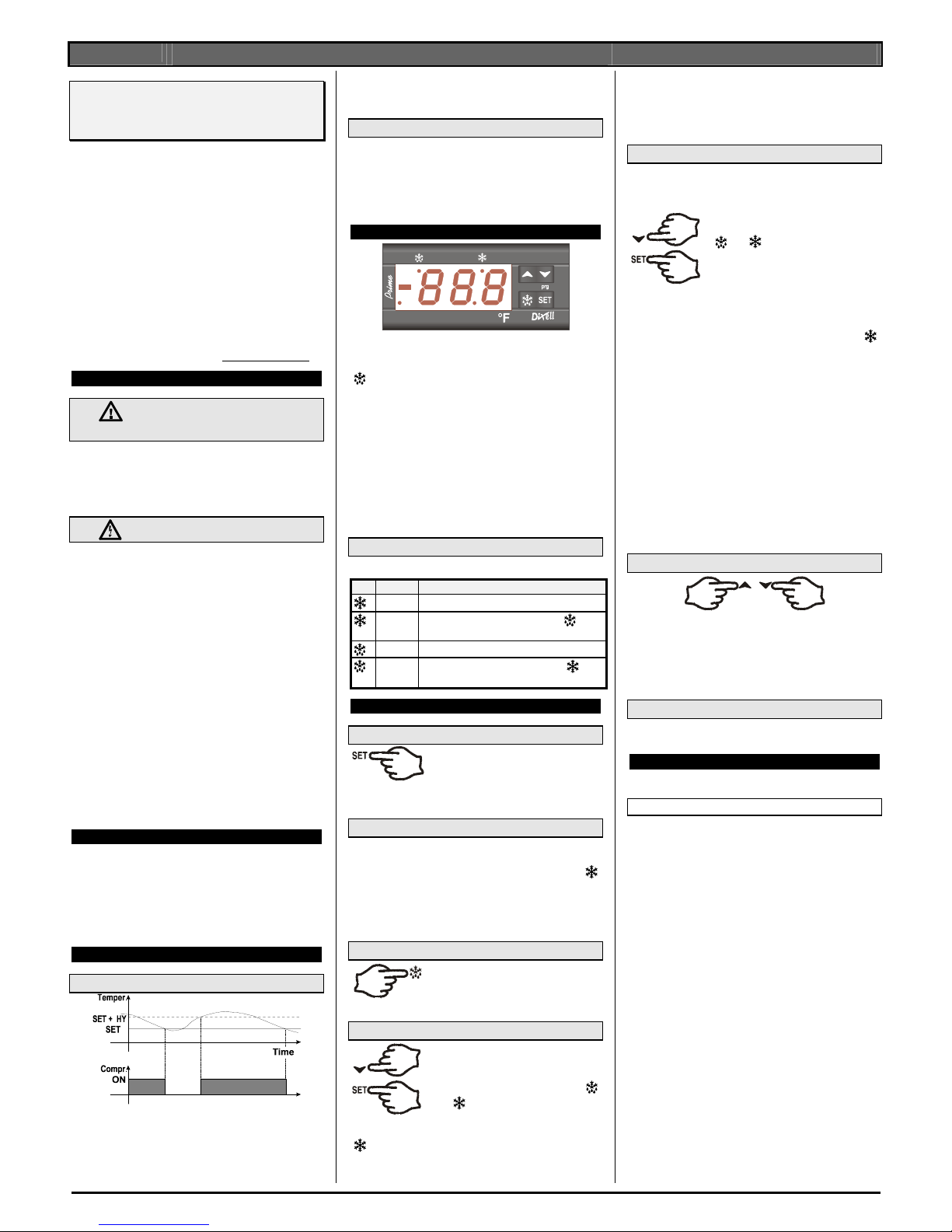
5.1 HOW TO SEE THE SETPOINT
1. Push and immediately release the
SET key: the display will show the
Set point value;
2. Push and immediately release the SET key or wait for 5
seconds to display the probe value again.
5.2 HOW TO CHANGE THE SETPOINT
1. Push the SET key for more than 2 seconds to change
the Set point value;
2. The value of the set point will be displayed and the
LED starts blinking;
3. To change the Set value push the o or narrows.
4. To memorise the new set point value push the SET key
again or wait 15s.
5.3 HOW TO START A MANUAL DEFROST
Push the DEF key for more than 2
seconds and a manual defrost will
start.
5.4 HOW TO CHANGE A PARAMETER VALUE
To change the parameter’s value
operate as follows:
1. Enter the Programming mode by
pressing the Set and nkey for 3s (
and start blinking).
2. Select the required parameter.
3. Press the “SET” key to display its value. (Now only the
LED is blinking).
4. Use o or nto change its value.
5. Press “SET” to store the new value and move to the
following parameter.
To exit: Press SET + UP or wait 15s without pressing a key.
NOTE: the set value is stored even when the procedure is
exited by waiting the time-out to expire.
5.5 THE HIDDEN MENU
The hidden menu Includes all the parameters of the
instrument.
5.5.1 HOW TO ENTER THE HIDDEN MENU
Enter the Programming mode by
pressing the Set + nkey for 3s
(and start blinking).
1. When a parameter is displayed
release and then press the Set+n
again for more than 7s. The Pr2 label will
be displayed immediately followed from the HY parameter.
NOW YOU ARE IN THE HIDDEN MENU.
2. Select the required parameter.
3. Press the “SET” key to display its value (Now only the
LED is blinking).
4. Use o or nto change its value.
5. Press “SET” to store the new value and move to the
following parameter.
To exit: Press SET + o or wait 15s without pressing a key.
NOTE: the set value is stored even when the procedure is
exited by waiting the time-out to expire.
5.5.2 HOW TO MOVE A PARAMETER FROM
THE HIDDEN MENU TO THE FIRST LEVEL
AND VICEVERSA.
Each parameter present in the HIDDEN MENU can be
removed or put into “THE FIRST LEVEL” (user level) by
pressing “SET + n”.
In the HIDDEN MENU when a parameter is present in Fisrt
Level the decimal point is on.
5.6 HOW TO LOCK THE KEYBOARD
1. Keep pressed for more than 3 s the o and nkeys.
2. The “POF” message will be displayed and the keyboard
will be locked. At this point it will be possible only to see
the set point or the MAX o Min temperature stored
3. If a key is pressed more than 3s the “POF” message will
be displayed.
5.7 TO UNLOCK THE KEYBOARD
Keep pressed together for more than 3s the o and nkeys
till the Pon message will be displayed.
6. LIST OF PARAMETERS
NOTE: the parameters preceded by dots are only in the
Hidden Menu.
REGULATION
Hy Differential: (0,1 ÷ 25,5°C / 1÷45 °F) Intervention
differential for set point. Compressor Cut IN is Set Point
Plus Differential (Hy). Compressor Cut OUT is when the
temperature reaches the set point.
• LS Minimum set point: (- 50°C÷SET / -58°F÷SET):
Sets the minimum acceptable value for the set point.
• US Maximum set point: (SET÷ 150°C / SET÷302°F).
Set the maximum acceptable value for set point.
• Ot Thermostat probe calibration: (-12.0÷12.0°C; --
21÷21°F) allows the adjustment of possible offset of the
thermostat probe.
• P2P Evaporator probe presence: n= not present:
the defrost stops by time; y= present: the defrost stops
by temperature.
• OE Evaporator probe calibration: (-12.0÷12.0°C; -
120÷120°F). allows to adjust possible offset of the
evaporator probe.
• OdS Outputs activation delay at start
up: (0÷255min) This function is enabled at the initial
start up of the instrument and inhibits any output
activation for the period of time set in the parameter.
AC Anti-short cycle delay: (0÷50 min) minimum interval
between the compressor stop and the following restart.
• COn Compressor ON time with faulty probe: (0÷255
min) time during which the compressor is active in case
of faulty thermostat probe. With COn=0 compressor is
always OFF.
XR20CE2probecooling XR20C 1/2
Dixell
Installing and Operating Instructions
XR20CE2probecooling XR20C 2/2
• COF Compressor OFF time with faulty probe:
(0÷255 min) time during which the compressor is OFF
in case of faulty thermostat probe. With COF=0
compressor is always active.
DISPLAY
• CF Temperature measurement unit: °C =
Celsius; °F= Fahrenheit. WARNING: When the
measurement unit is changed the SET point and the
values of the parameters Hy, LS, US and Ot have tobe
checked and modified if necessary).
rES Resolution (for °C): (in = 1°C; dE = 0.1 °C) allows the
decimal point displaying.
DEFROST
dtE Defrost termination temperature: (-50÷50 °C/
-58÷122°F) (Enabled only when P2P=y) sets the
temperature measured by the evaporator probe, which
causes the end of defrost.
IdF Interval between defrost cycles: (1÷120h) Determines
the time interval between the beginning of two defrost
cycles.
MdF Length for defrost: (0÷255min) It sets the defrost
duration.
• dFd Temperature displayed during defrost: (rt = real
temperature; it = temperature at defrost start; SEt = set
point; dEF = “dEF” label)
• dAd MAX display delay after defrost: (0÷255min).
Sets the maximum time between the end of defrost and
the restarting of the real room temperature display.
DIGITAL INPUT
i1P Digital input polarity: oP: the digital input is activated
by opening the contact; CL: the digital input is activated
by closing the contact.
did:(0÷255 min) door open signalling delay
• odc Compressor status when open door:
no=Digital Input not used CPr= Compressor OFF.
OTHER
rEL Software release for internal use.
Ptb Parameter table index: readable only. For internal use.
7. DIGITAL INPUT
7.1 DIGITAL INPUTS POLARITY
The digital input polarity depends on the “i1P” parameter.
i1P=CL: the input is activated by closing the contact.
i1P=OP: the input is activated by opening the contact
8. INSTALLATION AND MOUNTING
Instrument XR20C shall be mounted on panel, in a 29x71
mm hole, and fixed using the special brackets supplied.
To obtain an IP65 protection grade use the front panel rubber
gasket (mod. RG-C) as shown in figure.
The temperature range allowed for correct operation is 0÷60
°C. Avoid places subject to strong vibrations, corrosive
gases, excessive dirt or moisture. The same
recommendations apply to probes. Let air circulate by the
cooling holes.
9. ELECTRICAL CONNECTIONS
The instruments are provided with screw terminal block to
connect cables with a cross section up to 2,5 mm2. Heat-
resistant cables have to be used. Before connecting cables
make sure the power supply complies with the instrument’s
requirements. Separate the probe cables from the power
supply cables, from the outputs and the power
connections. Do not exceed the maximum current allowed
on each relay, in case of heavier loads use a suitable
external relay.
9.1 PROBE CONNECTION
The probes shall be mounted with the bulb upwards to
prevent damages due to casual liquid infiltration. It is
recommended to place the probe away from air streams to
correctly measure the average room temperature.
10. HOW TO USE THE HOT KEY
10.1 HOW TO PROGRAM A HOT KEY FROM THE
INSTRUMENT (UPLOAD)
1. Program one controller with the front keypad.
2. When the controller is ON, insert the “Hot key” and
push okey; the "uPL" message appears followed a
The word “End”
3. Push “SET” key and the End will stop being displayed.
4. Turn OFF the instrument remove the “Hot Key”, then
turn it ON again.
NOTE: the “Err” message is displayed for failed
programming. In this case push again okey if you want to
restart the upload again or remove the “Hot key” to abort the
operation.
10.2 HOW TO PROGRAM AN INSTRUMENT
USING A HOT KEY (DOWNLOAD)
1. Turn OFF the instrument.
2. Insert a programmed “Hot Key” into the 5 PIN
receptacle and then turn the Controller ON.
3. Automatically the parameter list of the “Hot Key” is
downloaded into the Controller memory, the “doL”
message is blinking followed a by “End”.
4. After 10 seconds the instrument will restart working
with the new parameters.
5. Remove the “Hot Key”.
NOTE the message “Err” is displayed for failed programming.
In this case turn the unit off and then on if you want to restart
the download again or remove the “Hot key” to abort the
operation.
11. ALARM SIGNALS
Message Cause Output
“EE” Data or memory failure
“P1”
Room probe failure Output according to par.
“Con” and“COF”
“P2”
2nd probe failure Output unchanged
“dA” Door open Regulation restarts
11.1 ALARM “EE”
The instrument is provided with an internal check verifying
memory integrity. Alarm “EE” flashes when a failure in the
internal memory is detected. In such case call the service.
11.2 ALARM RECOVERY
Probe alarm “P1 & P2” start some seconds after the fault in
the related probe; it automatically stops some seconds after
the probe restarts normal operation. Check connections
before replacing the probe.
Alarm dA will recover as soon as the digital input is disabled.
12. TECHNICAL DATA
Housing: self extinguishing ABS.
Case: XR20C frontal 32x74 mm; depth 60mm;
Mounting
XR20C panel mounting in a 71x29mm panel cut-out
Protection: IP20.
Frontal protection:
XR20C IP65 with frontal gasket RG-C (optional).
Connections: Screw terminal block ≤2,5 mm2heat-
resistant wiring.
Power supply: according to the model: 12Vac/dc, ±10%;
24Vac/dc, ±10%; 230Vac ±10%, 50/60Hz, 110Vac ±10%,
50/60Hz
Power absorption: 3VA max
Display: 3 digits, red LED, 14,2 mm high.
Inputs: 2 NTC probes. 1 Digital input
Relay outputs
Compressor:
SPST relay 16FLA/96LRA
Data storing: on the non-volatile memory (EEPROM).
Kind of action: 1B.
Pollution grade: normal
Software class: A.
Operating temperature: 0÷60 °C.
Storage temperature: -25÷60 °C.
Relative humidity: 20÷85% (no condensing)
Measuring and regulation range:
NTC probe: -40÷110°C (-58÷230°F)
Resolution: 0,1 °C or 1°C or 1 °F (selectable).
Accuracy (ambient temp. 25°C): ±0,7 °C ±1 digit
13. CONNECTIONS
13.1 XR20C: 16FLA COMPRESSOR
4567
9101112
Comp
Room
8
Hot Key
Line
Supply
120V~
120Vac supply: connect to the terminals 7 and 8.
OPTIONAL:
12Vac/dc supply: connect to the terminals 7 and 8.
24Vac/dc supply: connect to the terminals 7 and 8.
230Vac supply: connect to the terminals 7 and 8.
14. DEFAULT SETTING VALUES
Label Name Range °C/°F
Set Set point LS÷US 3/37
Hy Differential 0,1÷25.5°C/
1÷45°F 2/4
LS Minimum set point -50°C÷SET/
-58°F÷SET -40/
- 40
US Maximum set point SET÷150°C/
SET ÷230°F 110/
230
Ot Thermostat probe calibration -12÷12°C /
-21 ÷21°F 0/0
P2P 2nd probe presence Y/N Y
OE 2nd probe calibration -12÷12°C /-
120÷120°F
OdS Outputs delay at start up 0÷255 min 0
AC Anti-short cycle delay 0 ÷50 min 1
COn Compressor ON time with faulty
probe 0 ÷255 min 15
COF Compressor OFF time with faulty
probe 0 ÷255 min 30
CF Temperature measurement unit °C ÷°F °C/°F
rES Resolution in ÷dE dE/-
dtE Defrost end temp -50 ÷50 °C 46
IdF Interval between defrost cycles 1 ÷120 hour 8
MdF (Maximum) length for defrost 0 ÷255 min 20
dFd Displaying during defrost rt, it, SEt,
DEF it
dAd MAX display delay after defrost 0 ÷ 255 min 30
i1P Digital input polarity oP=opening;
CL=closing cL
did Digital input alarm delay 0÷255min 5
odc Compressor status with open door: No=No Digital
input used.
CPr; =
Compressor
off
no
rEL Software release -- -
Ptb Map code -- -
Hidden parameters
Dixell s.r.l. Z.I. Via dell’Industria, 27
32010 Pieve d’Alpago (BL) ITALY
tel. +39 - 0437 - 98 33 - fax +39 - 0437 - 98 93 13
E-mail: [email protected] - http://www.dixell.com

This manual suits for next models

2

Other dixell Thermostat manuals

dixell XR20CX Wiring diagram

dixell

dixell XR20CX Wiring diagram

dixell XR530D Wiring diagram

dixell

dixell XR530D Wiring diagram

dixell XR30C Instruction Manual

dixell

dixell XR30C Instruction Manual

dixell SE10-45-P User manual

dixell

dixell SE10-45-P User manual

dixell WING XW40LS Wiring diagram

dixell

dixell WING XW40LS Wiring diagram

dixell XR570C Instruction Manual

dixell

dixell XR570C Instruction Manual

dixell XH50P Instruction Manual

dixell

dixell XH50P Instruction Manual

dixell WING XW60L Wiring diagram

dixell

dixell WING XW60L Wiring diagram

Popular Thermostat manuals by other brands

Lennox iComfort SL18XC-01 Installer setup guide

Lennox

Lennox iComfort SL18XC-01 Installer setup guide

Emerson 1F85U-22NP Installation and operating instructions

Emerson

Emerson 1F85U-22NP Installation and operating instructions

Honeywell RTH5100B Quick installation guide

Honeywell

Honeywell RTH5100B Quick installation guide

Elko iNels RFTC-10/G manual

Elko

Elko iNels RFTC-10/G manual

Honeywell ATC928G3000 Frequently asked questions

Honeywell

Honeywell ATC928G3000 Frequently asked questions

White Rodgers BLUE 1F89-0211 Installation and operating instructions

White Rodgers

White Rodgers BLUE 1F89-0211 Installation and operating instructions

Danfoss BasicPlus2 user guide

Danfoss

Danfoss BasicPlus2 user guide

Sensi 1F95U-42WF, ST75 installation guide

Sensi

Sensi 1F95U-42WF, ST75 installation guide

SCI ERV-24-HC11 user manual

SCI

SCI ERV-24-HC11 user manual

PW maintenance DT-TS operating instructions

PW maintenance

PW maintenance DT-TS operating instructions

Inspire NS1001 installation guide

Inspire

Inspire NS1001 installation guide

Selmo Electronics MUSA Plus Eco manual

Selmo Electronics

Selmo Electronics MUSA Plus Eco manual

Technotherm TPF-Eco Control guide

Technotherm

Technotherm TPF-Eco Control guide

Neomitis RTE1RFD installation instructions

Neomitis

Neomitis RTE1RFD installation instructions

Watts Dual Sensing Thermostat Installation & operation

Watts

Watts Dual Sensing Thermostat Installation & operation

PHASELINER TS930 user guide

PHASELINER

PHASELINER TS930 user guide

momit Smart Thermostat user guide

momit

momit Smart Thermostat user guide

Pro 1 IAQ T855i quick start guide

Pro 1 IAQ

Pro 1 IAQ T855i quick start guide

manuals.online logo
manuals.online logoBrands
  • About & Mission
  • Contact us
  • Privacy Policy
  • Terms and Conditions

Copyright 2025 Manuals.Online. All Rights Reserved.