Dixon RZL-400 Operating instructions

Operating & Maintenance Manual
for
RZL-400 Series
Rotary Lobe Pumps
Dixon Sanitary
N25 W23040 Paul Road • Pewaukee, WI 53072
ph: 800.789.1718 • fx: 800.789.4046
dixonvalve.com

2 Rotary Lobe Pumps - RZL-400 Series800.789.1718
Table of Contents
Safety ................................................................................................................................................................................................... 3
Care of Stainless Steel......................................................................................................................................................................... 4
Technical Specications....................................................................................................................................................................... 5
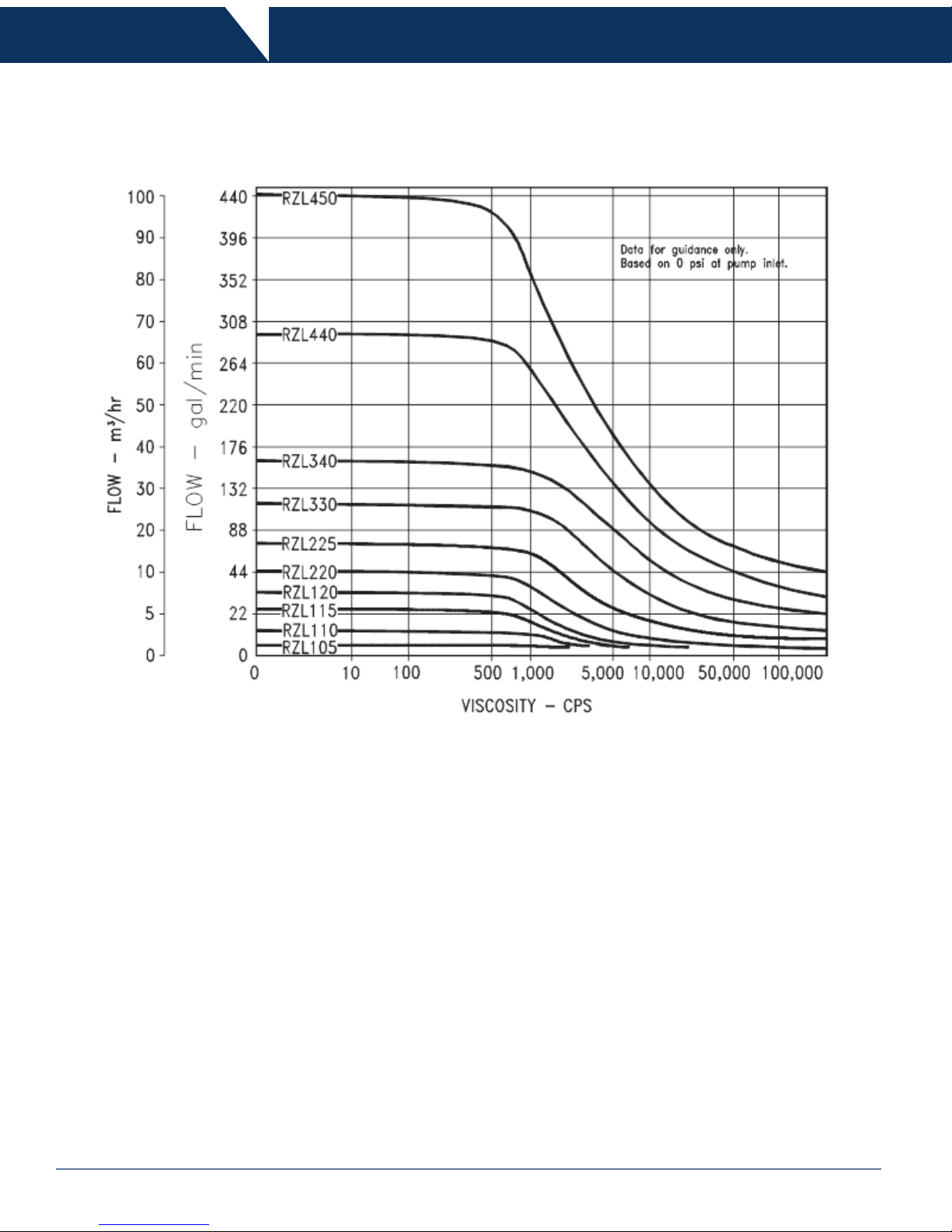
Family of curves ................................................................................................................................................................................... 6
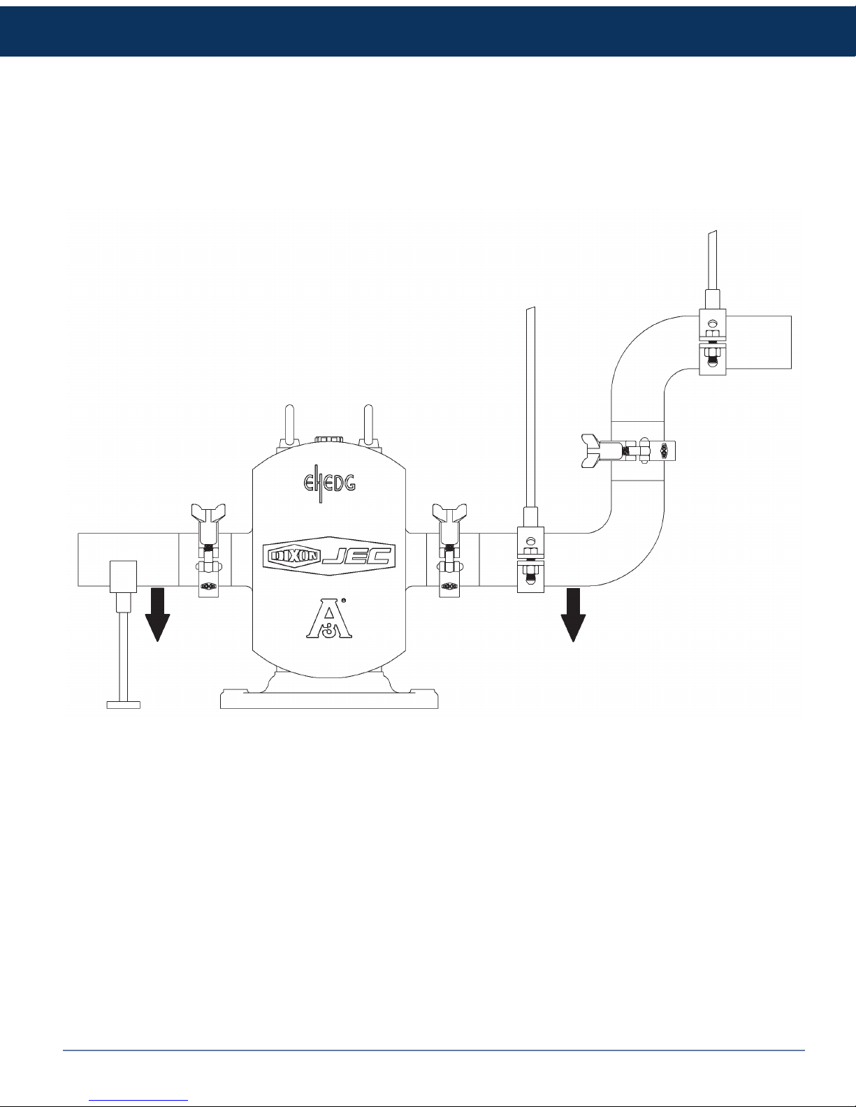
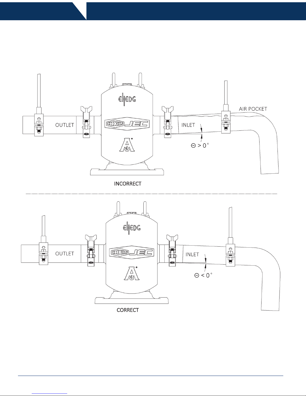
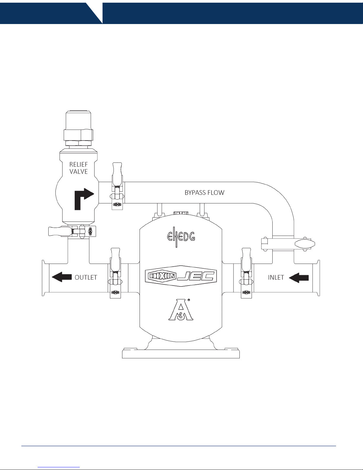
Unpacking Installation & Start Up.................................................................................................................................................... 7-16
Tools needed...................................................................................................................................................................................... 17
Maintenance.................................................................................................................................................................................. 17-55
Pump Housing Disassembly...................................................................................................................................................... 17-48
Single Mechanical Seal.......................................................................................................................................................... 17-25
Double Mechanical Seal......................................................................................................................................................... 26-35
Single O-ring Seal .................................................................................................................................................................. 36-41
Triple Lip Seal ........................................................................................................................................................................ 42-48
Inspection........................................................................................................................................................................................ 49
Pump Housing Assembly................................................................................................................................................................ 49
Rotor Clearance......................................................................................................................................................................... 50-52
Shimming .................................................................................................................................................................................... 52
Rotor Timing ................................................................................................................................................................................... 53
Gear Box Disassembly ................................................................................................................................................................... 54
Gear Box Assembly ........................................................................................................................................................................ 55
Scheduled Maintenance ................................................................................................................................................................. 55
Maximum RPM................................................................................................................................................................................... 56
Maximum Solids ................................................................................................................................................................................. 56
Dimensions......................................................................................................................................................................................... 57
Troubleshooting............................................................................................................................................................................. 58-60
BOM .............................................................................................................................................................................................. 61-73
Certicates..................................................................................................................................................................................... 74-75
Warranty............................................................................................................................................................................................. 76
Thank you for purchasing a Dixon Sanitary Product!
This manual contains installation, operation, disassembly and assembly instructions, maintenance procedures, troubleshooting and a
complete parts list for all RZL-Series positive displacement pumps.
READ THIS MANUAL carefully to learn how to service these pumps. Failure to do so could result in person injury or equipment
damage.

3Rotary Lobe Pumps - RZL-400 Series 800.789.1718
DO’S & DON’TS
DO read and understand these instructions before installing or using the pump.
DO use Dixon spare parts when replacing a component of the pump.
DO NOT service the pump while it is running.
DO NOT place the pump in an application where the service ratings are exceeded.
DO NOT modify the pump. Modifying the pump creates unsafe conditions and voids all warranties.
SAFETY PRECAUTIONS WHEN INSTALLING PUMP
DO use an authorized electrician when connecting the pump.
DO observe the mechanical limits of the pump (refer to the pump performance sheet).
DO install a throttling valve in the discharge line.
DO NOT install a throttling valve in the suction line.
SAFETY PRECAUTIONS WHEN OPERATING PUMP
DO allow only qualied personnel to operate this pump.
DO NOT start the pump until all personnel are clear.
DO NOT touch the pump or the lines when pumping hot uids or when performing Clean In Place (CIP) procedures.
DO NOT run the pump with BOTH the suction inlet and discharge outlet blocked. Running the pump with the inlet
blocked will cause serious damage to the pump.
DO NOT check pump rotation with liquid in the pump.
DO NOT run the pump with the front cover removed. The rotors and rotor case could be damaged or may cause severe
injury.
DO NOT operate the pump with the safety guard removed.
SAFETY PRECAUTIONS WHEN SERVICING PUMP
DO ensure the pump is cool to touch before performing service.
DO relieve all pressure and drain all uids from pump and connected piping before performing service.
DO ENSURE POWER TO THE UNIT HAS BEEN DISCONNECTED PRIOR TO PERFORMING ANY PUMP
MAINTENANCE OR CLEANING.
DO exercise caution and wear protective clothing when using lye or acid for cleaning.
Safety Information

4 Rotary Lobe Pumps - RZL-400 Series800.789.1718
Care of Stainless Steel
The stainless steel components in Dixon Sanitary equipment are machined, welded and assembled by skilled craftsmen using
manufacturing methods that preserve the corrosion-resistant quality of the stainless steel.
Retention of corrosion-resistant qualities under processing conditions requires regular attention to the precautions listed below.
1. Regularly check all electrical devices connected to the equipment for stray currents caused by improper grounding, damaged
insulation or other defects. Corrosion: Pitting often occurs when stray currents come in contact with moist stainless steel.
2. Never leave rubber mats, ttings, wrenches, etc. in contact with stainless steel. Corrosion: Pitting or galvanic action. Objects
retard complete drying, preventing air from reforming the protective oxide lm. Galvanic corrosion occurs when two dissimilar
metals touch when wet.
3. Immediately rinse equipment after use with warm water until the rinse water is clear. Clean the equipment (manual or CIP)
as soon as possible after rinsing. Corrosion: discoloration, deposits, pitting. Product deposits often cause pitting beneath the
particles.
4. Use only recommended cleaning compounds. Purchase chemicals from reputable and responsible chemical manufacturers
familiar with stainless steel processing equipment, they continuously check the effects of their products on stainless steel.
5. Use cleaning chemicals exactly as specied by the manufacturer. Do not use excessive concentrations, temperatures or exposure
times. Corrosion: Pitting, discoloration, stress cracks. Permanent damage often occurs from excessive chemical concentrations,
temperatures or exposure times.
6. For manual cleaning, use only soft non-metallic brushes, sponges or pads. Brush with the grain on polished surfaces, avoid
scratching the surface. Corrosion: Pitting, scratches. Metal brushes or sponges will scratch the surface and promote corrosion
over a period of time. Metal particles allowed to remain on a stainless steel surface will cause pitting.
7. Use chemical bactericides exactly as prescribed by the chemical manufacturer in concurrence with local health authority. Use
the lowest permissible concentration, temperature and exposure time possible. Flush immediately after bacterial treatment. In no
case should the solution be in contact with stainless steel more then 20 minutes. Corrosion: Protective lm destroyed. Chlorine
and other halogen bactericides can destroy the protective lm. A few degrees increase in temperature greatly increases chemical
activity and accelerates corrosion.
8. Regularly inspect the joints in pipelines. Be sure all connections are tight tting without binding. Corrosion: Crevice corrosion.
Small crevices caused by improperly seated gaskets will promote crevice corrosion. Stainless steel under stress will develop
stress cracking especially in the presence of bactericides containing chlorine.
9. Regularly inspect equipment for surface corrosion (i.e. pitting deposits, stress cracks, etc.). If deposit or color corrosion is
detected, remove it immediately using mild scouring powder and detergents. Rinse thoroughly and allow to air dry. Review
production and cleaning procedures to determine the cause. Note: If corrosion is not removed, the protective lm cannot be
restored and corrosion will continue at an accelerated rate.

5Rotary Lobe Pumps - RZL-400 Series 800.789.1718
RZL 400-Series Technical Data
Specications:
Model Maximum Differential Pressure (PSI) 1Maximum Flow Rate (GPM)
440 174 300
450 116 440
1Up to 435 PSI (30 bar) is available with Front Bearing Cover
•Temperature range: 14°F to 356°F (-10°C to 180°C)
•Viscosity range: Up to 1,000,000 cPs
•Noise level: 60 ~ 80 dB
Materials:
• Product wetted steel part: AISI 316L Stainless Steel (standard)
• Product wetted elastomers: EPDM (standard)
• Optional seals: Buna, FKM, PTFE Encapsulated and Peruor
Shaft Seals:
• Seal options: Single and Double Mechanical, Single and Double O-Ring and Triple Lip-seal
• Maximum ushing water pressure: 7 PSI (0.5 bar)
• Flushing water consumption: 30~60 cubic inches/min (0.25~0.5 liter/min)
•Stationary seal ring material: Tungsten Carbide
• Rotating seal ring material: Tungsten Carbide (standard) or Silicon Carbide (optional)
• O-ring material: EPDM (standard)
• Optional O-ring material: Buna, FKM & Peruor
• Triple lip seal material: PTFE(Polytetrauoroethylene)+Glass (standard) or PTFE+Copper (optional)
Rotor Information: Not all rotors available in all models.
• Single/bi-wing and bi-lobe/tri-lobe/heli-lobe are interchangeable
• Optional rotors: Multi-lobe, PTFE Coated, Hardened & Rubber Heli-lobe
Optional Information:
• Ultra clean version
• High pressure version up to 435 PSI (30 bar)
• Heating jacket on rotor case and front cover
• Rectangular inlet version
• Pressure relief front cover (not 3A)
• Surface hardening

6 Rotary Lobe Pumps - RZL-400 Series800.789.1718
Rotary Lobe Pump Composite
Family of Curves

7Rotary Lobe Pumps - RZL-400 Series 800.789.1718
Unpacking
Carefully unpack all parts of the pump and inspect for damage that may have occurred during shipment. Report any damages to the
carrier immediately.
The ports on the pump are protected with a plastic cover. If any covers are missing or damaged, inspect the ports on the pump
thoroughly for any damage.
If you are receiving a complete base mounted unit, please check shaft alignment as it may have changed during shipment.
The drawing below shows how the pump should be lifted. Ensure that the lifting equipment is correctly rated.

8 Rotary Lobe Pumps - RZL-400 Series800.789.1718
Installation & Start Up
Pump Mounting Adjustable:
•Adjustable leg base, commonly used for sanitary pumps for wash down under base. Can be easily moved or repositioned.
Mounting Congurations
Pump Mounting Casters:
• Portable bases – for movement to different locations. Can also be mounted on a cart with handles.

9Rotary Lobe Pumps - RZL-400 Series 800.789.1718
Installation & Start Up
Proper Installation
Piping Support:
• Weight of piping and uid – support piping independently with hangers or pedestals. On rectangular inlet ange pumps, hopper
should also be supported independently.

10 Rotary Lobe Pumps - RZL-400 Series800.789.1718
Installation & Start Up
Proper Installation (continued)
Piping Slope:
•Inlet side – slope piping up to inlet to avoid air pocket.

11Rotary Lobe Pumps - RZL-400 Series 800.789.1718
Installation & Start Up
Proper Installation (continued)
Pressure Gauges:
Pressure and vacuum gauges provide the easiest way to tell you something about the pump operation.
• Normal or abnormal pressures
• Overow conditions
• Indication of ow
• Changes in pump condition
• Changes in system conditions
• Changes in uid viscosity

12 Rotary Lobe Pumps - RZL-400 Series800.789.1718
Installation & Start Up
Proper Installation (continued)
Inlet Check Valve:
• Inlet side – use check valves to keep inlet line full, particularly with low viscosity uids, and in start-stop operation.
Outlet Check Valve:
• Inlet Vacuum Service – use check valve on outlet side.
• Prevents backow (air or uid)
• Facilitates initial start-up (minimizes differential pressure pump must supply to start ow)

13Rotary Lobe Pumps - RZL-400 Series 800.789.1718
Installation & Start Up
Proper Installation (continued)
Thermal Expansion:
• Thermal expansion of piping can cause tremendous forces. Use thermal expansion joints to minimize forces on pump. Flexible
joints can also be used to limit the transmission of mechanical vibration. Anchor free ends of any exible hose in system.
Isolation Valves:
• Isolation Valves – permit pump maintenance and removal safely without emptying entire system.

14 Rotary Lobe Pumps - RZL-400 Series800.789.1718
Installation & Start Up
Proper Installation (continued)
Relief Loop:
• Relief Valve – To protect the pump and piping system against excessive pressure, a relief valve should be installed. An integral
relief valve, designed to bypass the uid internally from the pump outlet to the inlet, should not be used on applications where the
discharge must be closed for more than a few minutes. Prolonged operation of the pump with closed discharge with cause heating
of the uid circulating through the relief valve.

15Rotary Lobe Pumps - RZL-400 Series 800.789.1718
Installation & Start Up
At Start Up
Pump Flow:
• All pumps are labeled with ow direction based on motor being wired for clockwise rotation. If motor is wired for counterclockwise
rotation, ow direction will be opposite of what is indicated on pump head.

16 Rotary Lobe Pumps - RZL-400 Series800.789.1718
Installation & Start Up
At Start Up
Pump Alignment:
• A exible coupling is used to compensate for end play and small differences in alignment. The pump and drive shaft should be
aligned as closely as possible.
• Check angular alignment using feeler or taper gauge.
• Adjust to get equal dimension at all points – at the same time, set space between coupling halves to the coupling manufacturer’s
recommended distance.
• Note: Pump is aligned prior to shipping, after installation verify alignment as misalignment may have occurred during shipment.

17Rotary Lobe Pumps - RZL-400 Series 800.789.1718
Tools Needed
• Rotor tool
• Plastic dowel
• Open ended wrench set
• Rubber mallet
• Flat head screw driver
• Feeler gauges
• Hex keys
• O-ring pick
• Spanner wrench
• Rotor extraction tool (optional)
Additional tools needed when assembling or disassembling gear box
• Spanner wrench
• Arbor press or bearing puller
Maintenance
Pump Housing Disassembly - Single Mechanical Seal
Prior to removal of pump, the shut-off valves in the suction and discharge lines must be closed. If there is any risk that product
may harden, crystallize or freeze in the pump it should be thoroughly drained and cleaned immediately after use. Same
attention applies if there is a seal ush option. Power needs to be locked out to prevent unintended start of the pump.
Note: Reference numbers are listed in the sectional view located on pages 61-73.
1. Loosen and remove the four hex nuts (33) from the front cover.

18 Rotary Lobe Pumps - RZL-400 Series800.789.1718
Maintenance
Pump Housing Disassembly - Single Mechanical Seal (continued)
3. Remove the cover O-ring (34).
2. Remove the cover (32). If it is stuck, tap the cover with a soft hammer.

19Rotary Lobe Pumps - RZL-400 Series 800.789.1718
Maintenance
Pump Housing Disassembly - Single Mechanical Seal (continued)
4. Remove the rotor retaining bolts (35). To remove the rotor retaining bolts, place the dowel between the rotors. Turn the rst rotor
bolt counter-clockwise.
5. Remove the rotor bolts (35), spring washers (36) and O-ring (37).

20 Rotary Lobe Pumps - RZL-400 Series800.789.1718
Maintenance
Pump Housing Disassembly - Single Mechanical Seal (continued)
6. Remove the rotors (38) from the pump housing (31) by pulling straight.
6a. If the rotors (38) will not come out freely, remove the stud bolt hex nuts (46) and then tap on the back of the inlet and outlet ports
with a soft hammer. Once the rotors (38) are loose, then push the casing (31) back towards the gear box and remove the rotors.
Table of contents
Other Dixon Water Pump manuals
Popular Water Pump manuals by other brands

IPM
IPM IP-05 Series Operation manual

Idex
Idex Blagdon Pump X75 Service and operating manual

Grundfos
Grundfos CM series Installation and operating instructions

Ranpump
Ranpump F50-PX Operating and maintenance manual

Tsurumi Pump
Tsurumi Pump HS2.4S Residue Kit Operation manual

SPIDO
SPIDO JETINOX 800 operating instructions

Johnson Pump
Johnson Pump AQUA JET WPS 3.4 instruction manual

Jung Pumpen
Jung Pumpen MULTIFREE V1D-01 Installation and operator's manual

Pond Boss
Pond Boss DLILYSOL40 manual

Flotec
Flotec FPSC5000A owner's manual

Becker
Becker DX 4.40K operating instructions

Silicon Solar
Silicon Solar AQUAJET-MAXFLOW-50 user manual