Cembre B68M-P18-KV-RC1 Manual

1
ELECTRO-HYDRAULIC BATTERY PUMP
RADIO CONTROLLED
17 M 251 U
B68M-P18-KV-RC1
B68M-P18A-KV-RC1
ENGLISH OPERATION AND MAINTENANCE MANUAL

2
FIG. 2
A
G
F
C
B
FIG. 1
1
5
9
10
12
8
7
3
2
4
2
11
D
6
E

3
~ 0 %
50 %
100 %
Battery
FIG. 4
3
FIG. 3
FIG. 5
P
Female
Quick coupler
Male
Quick coupler
Female
Quick coupler
Male
Quick coupler
Cutting
head
Battery pump ...RC1
Flexible
insulated hose
1
2

4
FIG. 6
example of a cutting operation within a manhole with user at a safe distance away.

5
FIG. 8
212 (7.3)
236 (9.3)
350 (13.8)
405 (15.9)
mm (inch)
OIL
1
Max. oil level
FIG. 7
1
WARNING: use dielectric oil only.
For type and quantity refer to
section 1, page 8.

6
Hydraulic pumps manufactured by Cembre S.p.A. are developed for use with hydraulic heads.
According to this specific use, they do not need and are not equipped with an oil non-return safety
system.
For this reason, use in applications different from those intended (for example with hydraulic jacks,
lifting systems or similar) can be dangerous for the operator.
Cembre S.p.A. does not accept any liability arising from the use of its hydraulics pumps for ap-
plications different from those listed in its catalogues or other documentation.
Do not use the pump for purposes other than those intended by Cembre S.p.A.
The operator should concentrate on the work being performed and be careful to maintain a ba-
lanced working position.
Avoid dirty surfaces: dust and sand are a danger to any Electro-hydraulic equipment.
Protect the pump and accessories from rain and moisture. Water will damage the pump and battery.
Do not connect the hydraulic head directly to the pump quick coupler but always use the specific
flexible hose.
The pump contains special insulating oil which must not be polluted with any other types of oil.
Never connect to a pump hydraulic heads that still contain oil, namely with the ram not fully retracted;
excess oil could cause the pump to malfunction.
Before disconnecting the flexible hose, check that the ram of the head is completely retracted, in
order to ensure that a sufficient quantity of oil is available for subsequent operations.
The pump is unsuitable for continuous use and should be allowed to cool down following uninter-
rupted, successive crimping operations; for instance, having exhausted a fully charged battery in
one session, delay battery replacement for a few minutes.
WARNINGS

7
Use and Care of rechargeable batteries
Recharge the supplied battery using the specific manufacturer’s charger only.
A charger intended for a specific type of battery may become a fire hazard if used with other types
of battery.
Use the tool with the specific intended battery pack only, the use of any other type of battery may
lead to a risk of injury or fire.
When the battery is not in use, store it away from other metal objects, such as paperclips, coins,
keys, nails, screws or other small metal objects that can create a connection between two terminals.
Keep batteries out of reach of children.
Short-circuiting the battery terminals can cause burns or fire.
If in very poor condition, a battery can leak liquid. Avoid contact with the eyes.
In the case of accidental contact, rinse immediately under running water.
If the liquid comes into contact with the eyes, seek medical assistance immediately. Battery liquid
can cause irritation or burns.
Keep batteries dry!
Keep batteries away from fire!
Never throw batteries into fire or water.
Always recycle batteries after use.
Never dispose of batteries with household waste; they must be deposited at the dedicated
collection points for disposal.
Transporting Li-Ion batteries
Lithium-Ion rechargeable batteries are subject to the legal requirements on hazardous goods. In the
event of road transport by the user, no further precautions are necessary.
In the event of third-party transport (e.g. transported by airplane or courier), transportation must
comply with the special requirements concerning packaging and labelling. We recommend that
you consult an expert.
Rechargeable batteries can only be transported if undamaged.
The packaging must prevent the batteries from moving around and exposed contacts must be
covered with adhesive tape.
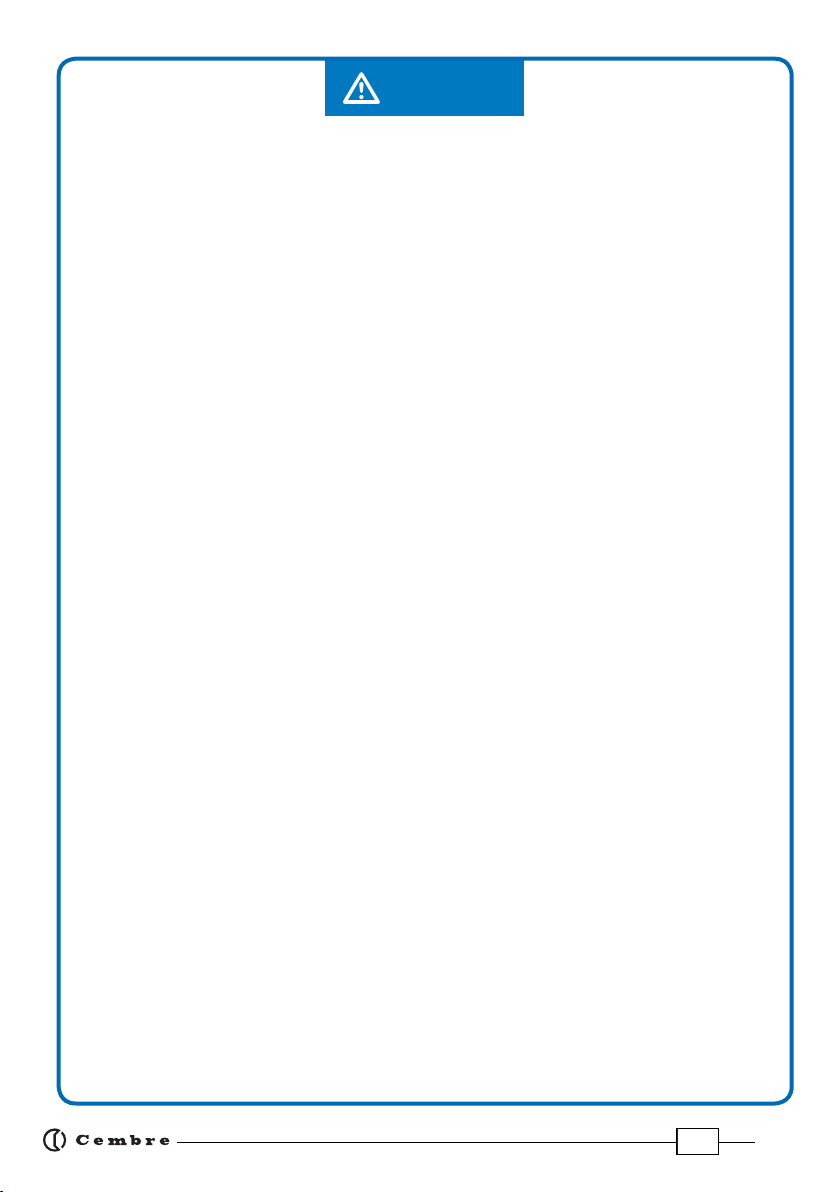
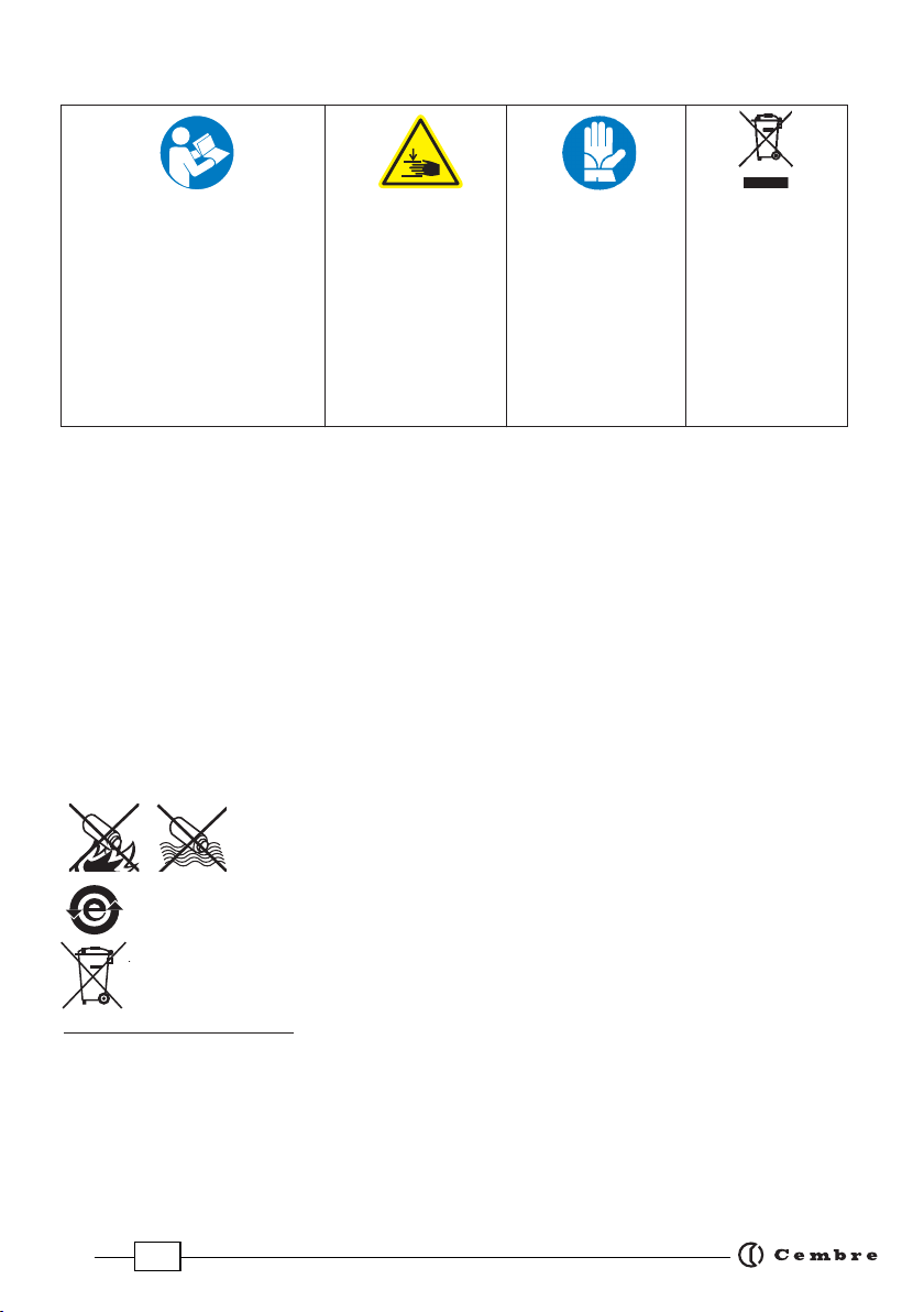
I
MPORTANT: Before using
the equipment, carefully
read all the warnings
and instructions in this
manual. Failure to follow
the warnings and instruc-
tions may result in electric
shock, fire and/or serious
injury.
When operating
the pump, keep
hands away from
the danger zone.
PUMP WARNING LABEL
User information
(Directives
2011/65/UE and
2012/19/UE), see
page 25.
Always wear safety
gloves when ope-
rating the equip-
ment.

8
(1) Directive 2006/42/EC, annexe 1, point 1.7.4.2 letter u
LpA = weighted continuous acoustic pressure level equivalent.
LpCPeak = maximum value of the weighted acoustic displacement pressure at the work place.
LWA = acoustic power level emitted by the machine.
(2) Directive 2006/42/EC, annexe 1, point 2.2.1.1
Weighted root mean square in frequency of the acceleration the upper limbs are exposed to for each biodynamic
reference axis. Tests carried out in compliance with the indications contained in EN ISO 5349-1/2 Standard, and
under operating conditions much more severe than those normally found.
1. GENERAL CHARACTERISTICS
Operating pressure
psi (bar) 10,573 (729)
Oil supply
high speed - low pressure
low speed - high pressure
US gpm (l/ min)
US gpm (l/ min)
0.34 (1,28)
0.07 (0,25)
Motor V DC 18
Radio receiver frequency
remote control Mhz 2405–2480
Operating temperature °F (°C) +5 to +122 (-15 to +50)
Oil reservoir capacity cu. in. (cm3)58.6 (960)
Recommended dielectric oil TOTAL DIEKAN 1640
Operating speed Double speed action: operation and automatic
switching from a rapid advancing speed to a slower,
more powerful working speed.
Degree of protection IP 20
Dimensions Ref. to Fig. 8 page 5
Weight with battery lbs (kg) 13.2 (6)
Safety
double safety system, electronic & mechanical safety valve
Acoustic noise (1) dB LpA 66.8 (A) LpCPeak 88 (C) LWA 82.8 (A)
Vibrations (2) m/s20.318
Rechargeable battery type CB1870L Li-Ion
V / Ah (Wh) 18 / 7.0 (126)
Weight lbs (kg) 2 (0,9)
B68M-P18-KV-RC1 B68M-P18A-KV-RC1
Battery charger
Input
Weight
type ASC30-36-EU ASC30-36-USA/CAN
V / Hz (W) 220 - 240 / 50 - 60 (85) 115 / 60 (85)
lbs (kg) 1.2 (0,53)

9
1.1) Compliance of use
- The B68M..-RC1 pump is designed to activate hydraulic heads for cutting conductor cables or
for crimping electrical cable lugs.
-The main use of the pump is combined with specific cutting heads to safely cut Copper and
Aluminium cable where the absence of voltage cannot be guaranteed.
- The dielectric oil used within the pump has special properties which insulate the pump from
the cutting head in the event that a live cable is accidentally cut.
- The innovative radio remote control is designed specifically for use within manholes allowing
the operator to control and operate the pump outside of the manhole at a safe distance away
from the cutting operation.
In order to trace all of the components of each complete unit, such as: pump, radio
control, the user should check the identification number reported on the tag attached
to each item.
1.2) Description
B68M....-RC1 includes the following (Ref. to Fig. 1):
(A) Canvas bag: made from sturdy fabric, allows users to store the pump and accessories.
(B) Battery charger: for recharging the batteries supplied; has “AIR COOLED” charging technol-
ogy and a processor for managing charging cycles.
To use, carefully follow the instructions in the battery charger user manual.
(C) USB cable: for transferring the data stored on the internal memory card to a PC.
(D) Rechargeable battery (2 pcs): 18 V - 7.0 Ah high capacity Lithium Ion battery.
Provides 100% of its energy between +5 and +122 °F (-15 and +50 °C).
Electronic control of the individual cells to prevent over-charging and under-discharging.
Greater longevity and ventilated recharging in short times thanks to AIR COOLED technology.
Timed automatic power off to optimize energy consumption.
Equipped with LED indicators that indicate the remaining battery life at any time by pressing
the button (P) (Ref. to Fig. 3):
4 LEDs illuminated: fully charged
2 LEDs illuminated: 50 % capacity
1 LED flashing: minimum charge, replace the battery.

10
With the battery inserted in the pump, the remaining battery life
can also be checked on the display, via touch button selection
(Ref. to section 5).
The display alongside indicates that the battery is low and the pump
will not start (Ref. to section 6.5).
The approximate time to fully recharge a CB1870L battery is about
50 minutes.
(E) Shoulder Strap: allows for easy transportation of the pump when connected to the rings
(2) on the pump.
It can also be used to secure the pump to the ladder in the manhole or to the manhole guard.
(F) Radio Remote Control RRC1: allows users to control the pump from a safe distance.
(Ref. to section 2 for further details).
(G) Portable hydraulic high capacity pump: driven by an 18V battery powered electric motor.
An Electronic Pressure Sensor (EPS) ensures precision and repeatability of the work cycles and
a maximum pressure valve to ensure maximum operator safety.
The memory card integrated into the pump allows the storage of the data relating to previous
operating cycles.
The default settings of the pump are:
Operating mode: CUTTING (Ref. to section 6.2 to choose CRIMPING operating mode).
Oil release mode: SMART (Ref. to section 6.3 for further details).
Pump control mode: RADIO ON, enables the radio remote control (Ref. to section 6.4 for further
details).
Main components (Ref. to Fig. 2):
1- OIL FILLER CAP: for accessing the pump’s oil tank.
2- STRAP FASTENING RING: to attach the shoulder strap and transport the pump.
It can be used to hang the radio control before the storage of the pump.
3- BATTERY RELEASE DEVICE: to lock/unlock the battery, press the button (3) and push the battery
downward to unlock it (Ref. to Fig. 4). Insert a battery from the bottom by sliding it into the side
guides until it locks.
4 - LED INDICATOR: to visually indicate to the operator the progress and the conclusion of the cut-
ting operation or to notify the operator of procedural or operational errors.
5- BUZZER: synchronized with the LED indicator to indicate audibly the operation in progress or
to notify the operator of procedural or operational errors.
6- RADIO RECEIVER BOX: includes the radio receiver of the remote control.
BATTERY Ï
Ð
max.
BATTERY BATTERY
Ï
Ð
min.

11
7 - MECHANICAL PRESSURE RELEASE BUTTON: if required, by
pressinghardonthe mechanical pressurerelease button, the
oil can be returned to the reservoir at any time, regardless of
the status of the battery.
8- I38F AUTOMATIC QUICK COUPLER: enables connection of the
insulated flexible hose. In order to attach or disconnect the
hose, pull the ring back.
The couplers cannot be disconnected if the system is under pressure.
The anti-dust protection cap must be used on both the hose and pump couplings to prevent
ingress of dirt or contamination.
9- CAPACITIVETOUCH BUTTON: for menu selection allows selection of various screens only when
the display is on (Ref. to section 5).
Do not apply pressure to or stab at the touch button, a light touch using a bare finger
is sufficient. The command pulse is sent when the finger releases the button.
The capacitive touch button may not work if touched using objects or when wearing
gloves, therefore always operate it using a bare finger.
10 - OLED DISPLAY: switches on when the control button (11) on the pump is pressed forward
and off automatically after 1 hour of non-operation.
11 - CONTROLBUTTON:rockertype,pushforwardoncetowake
up the pump and turn on the display.
NOTE:ifrequiredthecontrolbuttoncanbeusedtoactivate
the the pump motor or release the oil in manual mode
instead of the RRC1 radio remote control.
By default setting this function is disabled, to enable refer
to section 6.4.
12 - HANDLE:forsafeand balanced transportation of the pump.
11
release
start
7

12
2
1
3
7
6
5
4
FRONT BACK
RRC1
RADIO REMOTE CONTROL
PUMP RELEASE
ON/OFF
ON/OFF
2. RRC1 RADIO REMOTE CONTROL
FEATURES:
frequency band: 2405–2480 MHz
battery: 2 x 1.5V AAA / LR03 Alkaline
dimensions: 2.6 x 4.5 x 1.5 in (66 x 114 x 37.5 mm)
weight: 0.3 lbs (140 g)
IP code: 67
Operating temperature: -4 to +130 °F (-20 to +55 °C )
The RRC1 radio remote control allows users to control the pump.
Each RRC1 radio remote control is only paired to and should only be
used with the pump which it was supplied with. It is particularly suit-
able to utility cable cutting operations in limited access locations, eg.
in manholes, to enable working from a safe distance. Ergonomically
designed with a comfortable grip even while wearing work gloves.
The functions listed below are operable via the RRC1:
Function:
1 - ON/OFF BUTTON: to switch on or off the radio
remote control.
The radio remote control auto-
maticallyswitchesoff after3minutesof inactiv-
ity.
2- PUMPBUTTON:to startthepumpmotor
ortoresetanyalarmswhenpressedand
held for 2 seconds.
3- RELEASE BUTTON: can be operated at
any time (other than if there is an error
to release the pressure allowing oil to be
returned to the pump reservoir.
4- INDICATOR LED: the center LED flashes
whentheradiocontrolisON(greenwhen
the remote control battery is good, red
when the remote control battery is low).
5- HOOK: to hang the radio control to the rings (2)
of the pump or to the operator's belt during transportation or storage.
6- CLIP: to hang the radio control to the operator's belt.
7- POWER SWITCH: located on the back of the radio control, this switch stops the power supply
from the batteries. When in the off position (O), the radio control cannot be started.
When the
radio remote control is transported by airplane, the on/off switch must be in the off
position. The switch should not be used as an on/off button for the radio control.
RRC1
RADIO REMOTE CONTROL
PUMP RELEASE
ON/OFF

13
Changing RRC1 batteries:
When approximately 10% of battery capacity remains, the top LED lights red.
- Remove the back of the radio control by unscrewing the 5 screws.
- Replace the 2 x 1.5V AAA batteries with the correct polarity.
Use alkaline batteries for optimal performance.
- Screw the back of the radio control into place.
BATTERY PRECAUTIONS
As batteries contain flammable substances such as lithium or other organic
solvents, they may cause heating, rupture or ignition.
WARNING! Do not recharge the batteries. Attempts to recharge may cause rupture or hazard-
ous liquids to leak, which will corrode the equipment.
NOTE: Electronics and batteries must be physically separated before disposal.
Make sure that electronics or batteries are not disposed of in household waste.
- There is a risk of explosion if a battery is replaced with the incorrect type of battery.
- Do not short circuit, disassemble, deform or heat batteries.
- Keep batteries out of reach of children. If a child swallows a battery, seek immediate medical at-
tention.
- When discarding batteries, insulate the + and - terminals of batteries with insulating/masking
tape. Do not put multiple batteries into the same plastic bag.
- When improperly disposed, batteries may short circuit, causing them to become hot, burst or
ignite.
- Store in a cool place. Keep batteries away from direct sunlight, high temperatures, and high
humidity. Do not throw batteries onto fire.
3. INSULATED FLEXIBLE HOSE
High pressure flexible hoses are subject to a natural ageing process which can result
in a reduction in performance potentially affecting safety of the operator. As a result
their life span is limited. In order to ensure safe use of their units, Cembre recommends
replacing the hose within 10 years from the date printed on the fittings.
- Before using the pump always check the integrity of the flexible hose and the quick couplers
making sure there are no abrasions, cuts, deformations or swellings.
- Keep the flexible hose away from naked flames and sources of heat above 158°F (70°C).
- The factory fitted guards must be in place at each end of the flexible hose.
- Do not touch the flexible hose when under pressure.
- When using the pump, the flexible hose must be uncoiled and laid out straight.
The standard flexible hose is 33 ft (10 m) long. It is used to deliver oil under pressure, generated
by the pump, to the cutting head and as an insulating element between the head and the pump.
The insulated flexible hose is completely filled with an insulating oil with dielectric properties
which insulate the pump from the cutting head
The working range of the cutting head is 33 ft from the pump; this distance allows the
proper communication between the head and the pump.
In case longer insulated flexible hoses are used and the pump is kept outside of the
manhole, it is possible that the wireless blade travel sensor signal will not reach the pump.
+
+
-
-

14
4. INSTRUCTIONS FOR USE (Cutting operation)
A protected zone must be established around the work place where entry is forbidden.
STEP 1- Checking and testing the pump prior to cutting operations
Check all components (cutting head, flexible insulated hose, couplings and pump) before use to
verify there is no damage or leakage.
To use the cutting heads, carefully follow the instructions in the specific operation manual.
Checking and testing the unit prior to any cutting operations:
Check the battery charge and recharge it if necessary following the instructions in the battery
charger user manual. When a cutting operation begins, a check is made to determine whether
the battery charge is sufficient to complete the cutting operation. If this is not the case the
pump does not start. The LED (4) light will FLASH intermittently and the buzzer (5) will emit
an audible signal coordinated with the LED light.
Remove the battery from the pump.
Connect the flexible hose first to the cutting head and then to the pump (Ref. to Fig. 5).
Insert the battery into the pump.
Activate the pump by pressing forward the control button (11) on the pump,
the display lights up and the pump setting is displayed.
Turn on the radio control by pressing the ON/OFF button (1), the LED will
flash green, after 3 minutes the radio control automatically switches off.
Press the pump button (2) on the radio control to perform a test cutting operation.
During the operation the pump's LED light will FLASH intermittently and the buzzer will
emit an audible signal coordinated with the LED light (0.4s ON 0.4s OFF).
At the end of the operation when the max. pressure is reached, the pump will stop, the LED
light will FLASH intermittently and the buzzer will emit an audible signal coordinated with
theLED light (4s ON 1sOFF) the display will show the following flashing screen
(Ref. to section 6.5 for further details).
Release the finger from the radio control so to allow the pump proceeding
with the SMART RELEASE operation thus check that the blades are fully retracted to the start
position.
Remove the battery from the pump.
Disconnect the flexible hose from the pump and cutting head.
Cutting operations must be strictly in accordance with the
safety and working procedures established by the respon-
sible power utility.
Pp= 729 bar
OK

15
At the end of the operation, in the event of a very quickly flashing LED
light (0.1s ON 0.1s OFF) and an intermittent buzzer coordinated with
the LED light, this is to inform the operator that the maximum pres-
sure has not been reached. The display will show the following flashing screen
"ERROR" (Ref. to section 6.6 for further details).
STEP 2 – Bringing the cutting head down into the manhole
Secure the pump in proximity of the manhole or to the ladder, using the shoulder strap supplied
(Ref. to Fig. 6). The maximum distance between the cutting head and the pump is 33 ft (10
m) assuming that the pump is positioned in proximity of the manhole or on the ladder under
the street level.
Do not place the pump on dirty surfaces or in the presence of water.
Lower the cutting head and the flexible hose into the manhole.
Position the blades of the cutting head perpendicularly around the cable that has been identi-
fied for the cut, as described in the operation manual of the cutting head.
Stabilize the cutting head position and support the head by strapping it to the above wires or
cable holders. It is possible to hook the cutting head with the SS-TCY strap hooked to the hang-
ing points of the head.
Connect one end of the grounding wire to the cutting head and the other end to the relevant
grounding attachment (Ref. to operation manual of the cutting head).
Connect the flexible hose to the cutting head (Ref. to Fig. 5),
the operator should now leave the manhole.
After all personnel have exited the manhole or cable space,
connect the flexible hose to the pump (Ref. to Fig. 5).
Insert the battery.
Wake up the pump by pressing forward the control button (11)
(display ON).
STEP 3 – Cutting operation
A protected zone must be established around the work place where entry is forbidden.
Switch on the radio control by pressing the start ON/OFF button (1), the LED will flash green.
In proximity of the manhole, at a safe distance, push the pump button (2) on the radio control
to start the cutting operation (Ref. to Fig. 4). The maximum distance between radio control
and pump is 66 ft (20 m) if within line of sight.
During the cutting operation the pump's LED light will flash intermittently and the
buzzer emits an audible signal coordinated with the LED light (0.4s ON 0.4s OFF).
In the event that the buzzer is not heard, hold the pump button (2) for 1 minute, after
1 minute the pump button can be released to start the automatic release of the cutting blades.
11
ERROR
Ï
Ð

16
STEP 4 – Checking the unit after the cutting operation
Look the pump: at the end of the operation when the max. pressure (Pp) is
reached, the pump stops. The LED light FLASH intermittently and the buzzer
emit an audible signal coordinated with the LED light (4s ON 1s OFF) the
display show the following flashing screen, with “OK” to confirm the correct operation.
Beforeapproachingthe cutting area, strictly followthesafety and working procedures
established by the responsible power utility.
Access the area and remove the cutting head.
In case the blades are jammed after the cut, you can activate the FORCED RELEASE
MODE by pressing the release button 3 times within 2 seconds; refer to section 6.3.1
for further details.
At the end of the operation, in the event of a very quickly flashing LED
light (0.1s ON 0.1s OFF) and an intermittent buzzer coordinated with
theLEDlight,thisis to informthe operatorthatthemaximum pressure
has not been reached. The display will show the following flashing screen "ERROR".
In order to reset the alarm, press the pump button on the radio control once for 2 seconds.
Try to repeat the cycle by holding the pump button until the motor switches off automatically.
Before approaching the cutting area to check the problem, strictly follow the safety
and working procedures established by the responsible power utility.
WARNING: In case of accidentally cutting live cable, strictly follow the working proce-
dures established by the responsible power utility.
ERROR
Ï
Ð
Pp= 729 bar
OK

17
5. INSTRUCTIONS FOR USE (Crimping operation)
The pump is suitable for use with Cembre KV type protected crimping heads.
The default settings of the pump are:
- Operating mode: CUTTING (Ref. to section 6.2 to choose CRIMPING operating mode).
- Oil release mode: SMART (Ref. to section 6.3 for further details).
- Pump control mode: RADIO ON, operated by radio remote control only (Ref. to section 6.4 for
further details).
For a crimping operation select the crimping mode via the display, before starting any
crimping operations.
When the crimping mode is active, the LED light (4) and the buzzer (5) are deactivated.
When the battery is removed from the pump or after 1hour of inactivity (display OFF),
once you wake the pump up, it will always start with the default setting:
CUTTING MODE, SMART RELEASE and RADIO ON.
Connect the flexible hose, first to the head and then to the pump.
Press the control button (11) on the pump once to activate the pump, display ON.
Switch on the radio control by pressing the ON/OFF button (1).
Press the pump button (2), this activates the motor of the pump that feeds
the hydraulic head connected to it, pressurizing the oil.
Once the set pressure (Pn) is reached the pump will be switched off automati-
cally, the display will briefly showthemaximumpressurereached (Pp)followed
by “OK” to confirm the correct operation.
Releasing the pump button before the automatic stopping of the motor will
cause the pump to stop, keeping the oil pressure stable (Pp) at its current pres-
sure level. To complete the operation press the pump button once more until
the motor stops automatically.
At the end of the cycle, releasing the pump button will start the automatic
release of the ram and will allow return of the oil to the oil reservoir in the
pump (Ref. to section 6.3 for further details).
The display "ERROR" combined with 3 beeps and the LED flashing,
indicates an incorrect crimping procedure; the oil return phase oc-
curred too early without waiting for the motor to be automatically
switched off and therefore the minimum set pressure was not reached.
Repeat the crimping cycle by holding down the start button until the motor is automatically
switched off.
When a crimping head is used, always press and hold the pump button until the motor stops
automatically.
Pn= 729 bar
OK
Pn= 729 bar
Pp = 731 bar
Pn= 729 bar
P= 0 bar
ERROR
Ï
Ð

18
B68RC
NR 17AW125
10
29990
3
BATTERY
RC ON
RESET
SW:S1J76202
P = 0 bar
max 90°
60°
* 1
* 2
3
4
5
* 6
* 7
* 8
* 9
10
RC OFF
P = 0 psi
6. NAVIGATION MENU / DISPLAY
The OLED display (10) is activated with a push of the control but-
ton (11) on the pump. To navigate through the various screens
in the main menu, touch the capacitive button (9) repeatedly.
6.1) Structure of the "main menu"
Operating pressure, expressed in bar.
Pump default setting (CUTTING & SMART RELEASE)
Operating pressure, expressed in psi.
Pump default setting (CUTTING & SMART RELEASE)
Operating mode set.
(Ref. to section 6.2 for further details).
Release mode set.
(Ref. to section 6.3 for further details).
Pump control mode set.
(Ref. to section 6.4 for further details).
Battery charge level.
No. of cycles performed.
No. of cycles before scheduled recommended maintenance.
Cembre logo, pump model.
Pump serial no.
Actual temperature (°C) of the pump motor.
Return to original default settings.
Firmware version (Ref. to section 6.7 for further details).
9
10

19
(*) Screens 1-2-6-7-8-9 can be set as the“main screen”which is shown
on the display every time the pump is operated; to do this, when the
pre-selected screen is displayed, hold the finger on the touch button
(9) until a confirmation “beep” is heard.
6.2) Choosing the "operating mode"
The “operating mode” allows the user to define the pump function depending on the type of
hydraulic head connected. This enables the optimization of the job cycle and discharging of the
battery. It is possible to choose between two different operating modes:
CUTTING (default setting) CRIMPING
Operating mode Associated pictogram Function
CUTTING
default setting
Specifically for using the pump with Cembre hydraulic
heads for cutting electrical conductors where the absence
of voltage cannot be guaranteed.
CRIMPING
Specifically for using the pump with Cembre hydraulic
heads for crimping of electrical connectors.
NOTE: When the crimping mode is active, the LED light
and the buzzer are deactivated.
To change the desired “operating mode”, proceed as follows:
- Select screen 3 from the “main menu” (Ref. to section 6.1), hold the finger on the touch button (9) until a
confirmation “beep”is heard, the selected operation mode is shown by filling the related pictogram.
When the battery is removed from the pump or after 1 hour of inactivity (display OFF),
once you wake the pump up, it will always start with the default setting, CUTTING
MODE.
BEEP
2

20
6.3) Change the "release mode"
The method of discharging the oil into the pump’s tank can be carried out in two different ways,
depending on the mode set in the menu:
Release mode Associated pictogram Function
SMART
default setting
By releasing the pump button the oil is returned in full to
the pump reservoir only following automatic shut-off of
the motor.
During the return phase, pressing the buttons allows the
head ram retraction to be interrupted at any point.
MANUAL
To return the oil to the pump reservoir it is necessary to
press and hold the release button.
During the return phase, by releasing the button it is pos-
sible for head ram retraction to be interrupted at any point.
To change the "release mode", proceed as follows:
- Select screen 4 from the “main menu” (Ref. to section 6.1), hold the finger on the touch button(9) until a
confirmation “beep”is heard, the choice made is show by the related pictogram.
When the battery is removed from the pump or after 1 hour of inactivity (display OFF),
once you wake the pump up, it will always start with the default setting, SMART mode.
6.3.1) Extended release phase
If necessary, the phase of discharging the oil into the pump’s tank can be extended, leaving the
release valve open for 60 seconds.
This function is useful in the event that the blades are jammed after the cutting operation. It allows
the operator to work on the cutting head using both hands in case of a blade jamming.
To activate "extended release" proceed as follows:
- Press quickly (3 times within 2 seconds) the release button on the radio con-
trol RRC1 or the button (11) backward on the pump if RC mode is disabled.
The operation is then reported on the display by a counter associated with an
intermittent buzzer.
- In order to stop the countdown before reaching zero, press the pump button
on the radio control once for 2 seconds.
58
01
59
60
.........
This manual suits for next models
4
Table of contents
Other Cembre Water Pump manuals

Cembre
Cembre PO7000 User manual

Cembre
Cembre B70M-P36 User manual

Cembre
Cembre B1300PL User manual

Cembre
Cembre CPE-0-P12N User manual

Cembre
Cembre B68M-P18 User manual

Cembre
Cembre CPE-1 User manual

Cembre
Cembre B70M-P24 User manual

Cembre
Cembre CPP-0 User manual

Cembre
Cembre PO8500 User manual

Cembre
Cembre PO7000 User manual