DJ'S Light Emotion TE-X150 User manual

T
ABLE OF CONTENTS
PART1 PRODUCT(GENERAL)...........................................................
1.1--PRODUCT INTRODUCTION....................................................................
1.2--PRODUCT OVERVIEW...........................................................................
1.3--TECHNICAL SPECIFICATIONS...............................................................
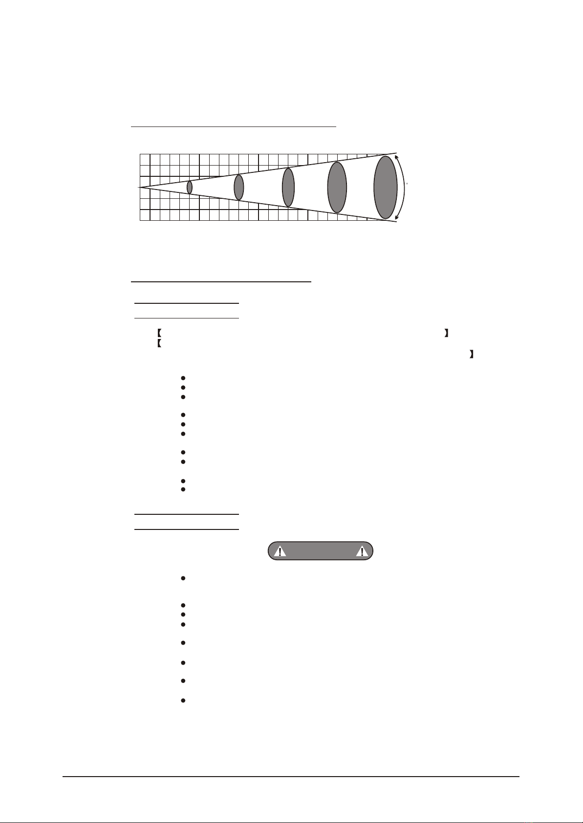
1.4--PHOTOMETRIC DATA............................................................................
1.5--SAFETY WARNING................................................................................
PART2 INSTALLATION.....................................................................
2.1--FUSE REPLACEMENT...........................................................................
2.2--SETTING UP(STANDALONE).................................................................
2.3--LED PCBREPLACEMENT......................................................................
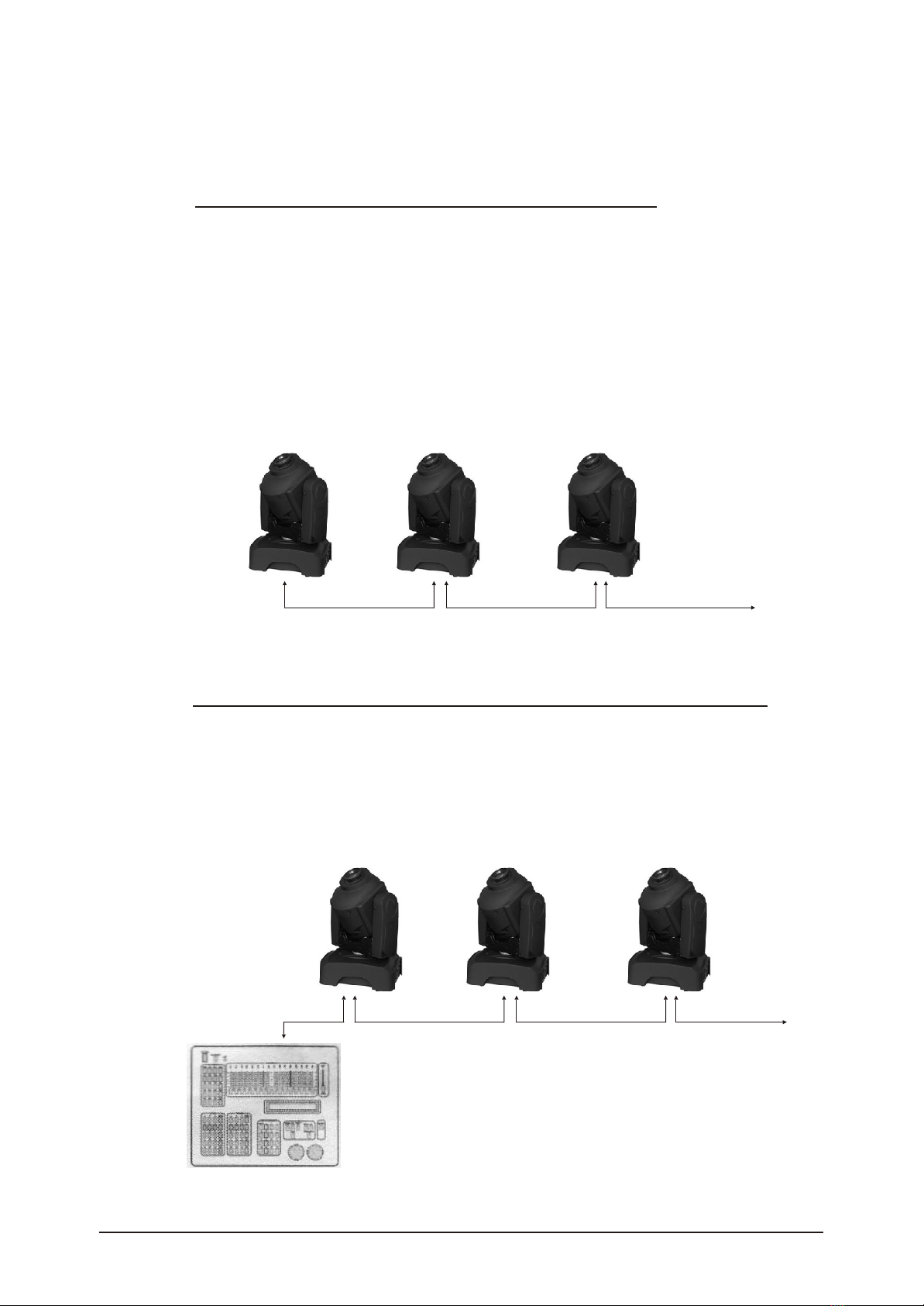
2.4--SETTING UP(MASTER/SLAVE)..............................................................
2.5--SETTING UP(DMX512 CONTROLLER.....................................................
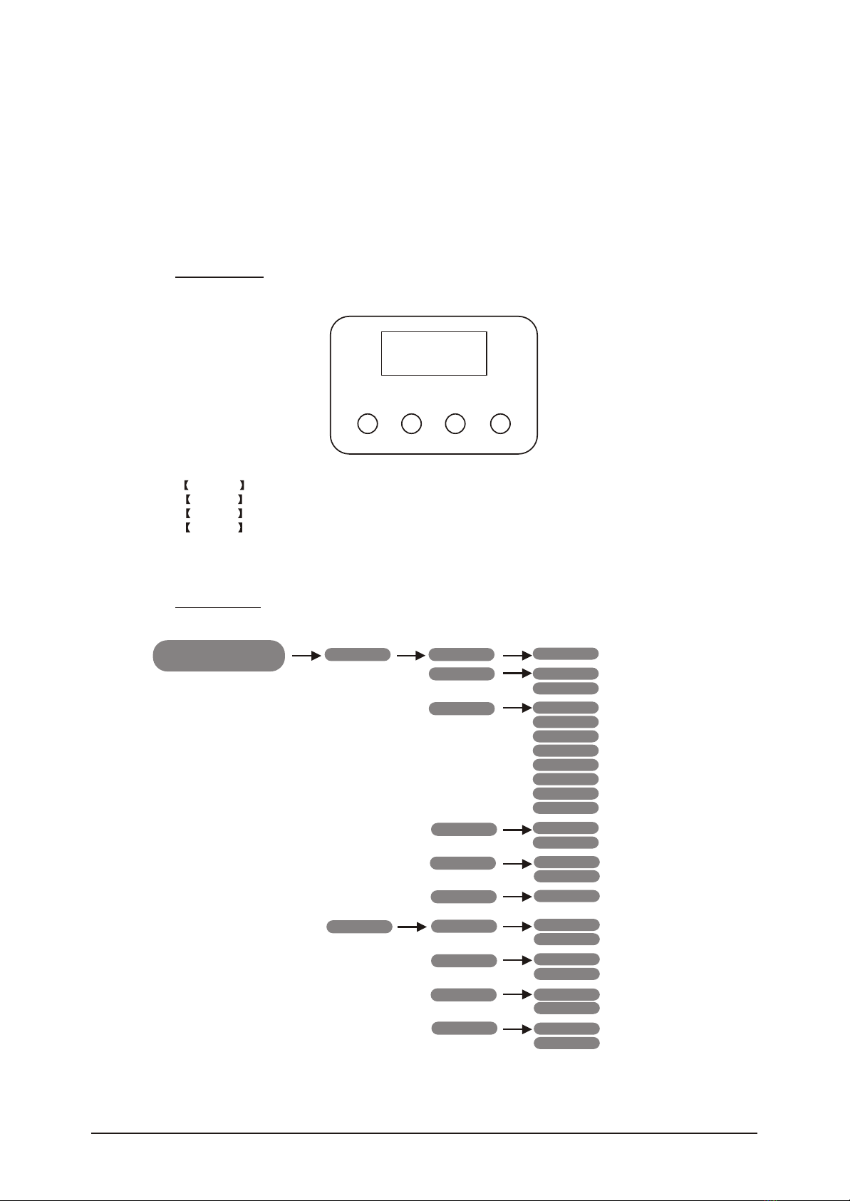
PART3 DISPLAY PANEL OPERATION.................................................
3.1--BASIC.................................................................................................
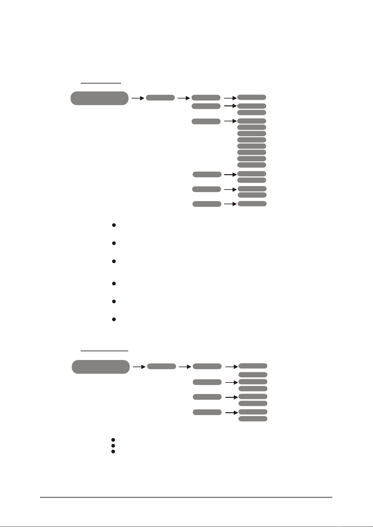
3.2--MENU..................................................................................................
3.3--INTRO.................................................................................................
3.4--INVERT................................................................................................
3.5--RANGE................................................................................................
3.6--SPECIAL.............................................................................................
3.7--EDIT....................................................................................................
3.8--DEFAULIT............................................................................................
PART4 USING A DMX512 CONTROLLER.............................................
4.1--BASIC ADDRESSING............................................................................
4.2--CHANNEL ASSIGNMENT.......................................................................
PART5 APPENDIX...........................................................................
5.1--TROUBLE SHOOTING...........................................................................
1
1
2
3
3
4
4
4
5
6
6
7
7
7
9
9
10
10
11
11
12
12
12
15
15

PRODUCT (GENERAL)
1
1.1
PRODUCT INTRODUCTION
This product is designed for indoor use only. Suitable for stage. Bar or nightclub
applications. Direct input of DMX512 signal allows the fixtures to be controlled from any
DMX512 controller. The fixture is fully programmable with one custom program available
and is supplied withtwo automatic programs (all accessible from DMX512 controller).This
product can beoperated as a single unit or with multiple units for large applications.
1.2
PRODUCT OVERVIEW
No
1
2
3
4
5
6
7
8
9
10
11
12
ITEM
Head
Arm
Base
Menu
Enter
Down
Up
Switch
Fuse
Power input
DMX 3-PIN signaloutput
DMX 3-PIN signaliutput
1 PRODUCT(GENERAL) 1
1
2
3

1 PRODUCT(GENERAL) 2
1.3
TECHNICAL SPECIFICATIONS
Electrical
Voltage:AC100-240V, 50/60Hz
Rated Power:75W
LED
LED:1PC(25W white)
Cooling:Forced air convection
Optical System
Focus:Manual linear focus
Dimmer:0-100%
Strobe:0-20Hz
3-facet Prism
Operation
Control mode:DMX512/Master-Slave/Auto/Custom/Sound
LCD display
DMX512 Chs: 9 CHS/12CHS
Pan/Tilt
Pan 540 Tilt270
Pan/Tilt speed
User-selectable Pan/Tiltranges
Reverse Pan/Tilt movement
Rotating Gobo
7 Gobo(interchangeable)
Gobo-flow effect
Gobo shake
Bi-directional rotation
Color
9 dichroic-filters
Rainbow-flow effect
Other features
Custom program(255 steps)
Size:240x200x354mm
Weight:7kg

1 PRODUCT(GENERAL) 3
1.4 PHOTOMETRIC DATA
1.5 SAFETY WARNING
IMPORTANT
ATTENTION
PLEASE CONFIRM THAT THE POWER SUPPLYSTATED ON THE
PRODUCT IS THE SAME AS THE MAINS POWER SUPPLT IN YOUR AREA.
ALWAYS READ THE USER MANUAL BEFORE OPERATION.
This product must be installed by a qualified professional
Always operate the equipment as described in the user manual.
A minimum distanceof 0.5m must be maintained between the equipment and
combustible surface.
The product must always be placed in a well ventilated area.
Alwas make sure that the equipmentis installed securely.
DO NOTstand closeto theequipment andstare directlyinto the LED light
source.
Always disconnect the power supply before attempting and maintenance.
Alwas make sure that the supporting structure is solid and can support the
combined weight ofthe products.
The earth wire must always be connected to the ground.
Do not touch the power cables if your hands are wet.
This product left the place ofmanufacture in perfectcondition. In orderto
maintain this condition and for safe operation,the user must always follow the
instructions and safety warnings described in this user manual.
Avoid shakingor strongimpacts toany partof theequipment.
Make sure that all parts ofthe equipment are kept clean and free of dust.
Always make sure that the power connections are connected correct and
secure.
If there is any malfunction ofthe equipment,contact your distributor
immediately.
When transferring the product,it is advisable to use the original packaging in
which the productleft the factory.
Shields,lenses or ultraviolet screens shallbe changed if they have become
damaged to such an extent that their effectivenessis impaired.
The lamp(LED) shall be changed if it has become damaged or thermally
deformed.
ATTENTION
0
2000 588 256 147 97 LUX
2(0.5) 4(1.1) 6(1.7) 8(2.2)
16
100Distance(m)
2.8Diameter(m)

2 INSTALLATION 4
INSTALLATION
2
2.1 FUSE REPLACEMENT
2.2 SETTING UP (STAND ALONE)
Remove thesafety capby ascrewdriver.
Fetch theold fusefrom safetycap.
Install anew fuse.
Install thesafety cap.
The LED fixture can be used as stand alone unit. The stand alone functions AUTO 1,
AUTO 2, SOUND 1, SOUND2and CUSTOM can beactivated withoutthe needto connect
Simply, access the <operation>menu from the DISPLAY and select the target program to
to anycontroller orconnecting toany otherequipment.
activate.
Safety Cap
Fuse

2 INSTALLATION 5
2.3 LED PCB PEPLACEMENT
Take offthe head cover.
Remove the fan cover, fan,fan supports,heat sink step by step.
Replace the new LED PCB.
Install all parts on the original position.
Fan supports
Fan
Heat sink
LED PCB
23 lenses

2 INSTALLATION 6
2.4 SETTING UP(MASTER/SLAVE)
When unitsare connected in series using DMX512signal cableconnect the units as shown
in thediagram below
Connect the (male) 3 pin connector side of the DMX cable to the output (female) 3 pin
connector ofthe first(MASTER) fixture.
Connect theend of thecable coming from the MASTER fixturewhich willhave a (female) 3
pin connector to the input connector of the next fixture consisting of a (male) 3 pin
connector.
Then proceedto connect from the output asstatedabove to the input ofthe following fixture
and soon.
Set thefirst unit inthe serise toone of theSTAND ALONE modes as described in section
2.2
All otherunitsin the serise should be setto <SLAVE>from the <operation>menu.
2.5 SETTING UP (DMX512 CONTROLLER)
When units are connected in series to aDMX512 controller and other DMX512 equipment,
connect theequipment as shown in the diagrambelow.
Connect the (male) 3 pin connector side of the DMX cable to the output (female) 3 pin
connector ofthe controller.
Connect the end of the cable coming from the controller which will have a (female) 3 pin
connector tothe input connector ofthe next fixtureconsisting of a(male) 3 pinconnector.
Then proceedto connect from the output as stated above to theinput ofthe following fixture
and soon.
If over32pcs fixtures connected ,the amplifier is needed.
DMX512
CONTROLLER
MASTER
MASTER
SLAVE
SLAVE
SLAVE
SLAVE

3 DISPLAYPANEL OPERATION 7
DISPLAY PANEL OPERATION
3
3.1 BASIC
MENU ENTER DOWN UP
The LED fixture is mounted with a LCD display and 4 controlbuttons.
Scroll through the main menu or exit from the current sub-menu
Enter the currently selected menu or confirm the current function value
Scroll DOWN through the menu list or decrease the value of the current function value
Scroll UPthrough the menu list or increase the value of the current function
MENU
ENTER
DOWN
UP
3.2 MENU
MENU Intro Address
Reset
Run
(001-512)
Yes
No
DMX512
Auto 1
Auto 2
Sound 1
Sound 2
Custom
Test
Slave
Invert
Channels
Display
Info
Pan
Tilt
Color
Use
Basic
Advanced
60 close
Bright
Edition
Normal
Reverse
Normal
Step
Linear
No
Yes
Reverse

3 DISPLAYPANEL OPERATION 8
Range P/start
P/Finish
T/start
T/Finish
Use
(000-255)
(000-255)
(000-255)
(000-255)
No
Yes
Black No
Yes
Special
Reset Dmx
System
Step (000-255)
Edit
Pan (000-255)
Tilt
Speed
Color
Gobo
(000-255)
(000-255)
(000-255)
(000-255)
Gobo.rot
Prism
Dimmer
Strobe
Time
Use
(000-255)
(000-255)
(000-255)
(000-255)
(000-255)
No
Yes
Default No
Yes
Default

3 DISPLAYPANEL OPERATION 9
3.3 INTRO
MENU Intro Address
Reset
Run
(001-512)
Yes
No
DMX512
Auto 1
Auto 2
Sound 1
Sound 2
Custom
Test
Slave
Channels
Display
Info
Basic
Advanced
60 close
Bright
Edition
[Address]
Enter [ Address ] to set the DMX Address, which is from (001-512)
In order to rest custom modestto default, select [ Reset ]
Enter [ Run ] toselect the operation mode; [DMAX512] ; [Auto1];
[ Auto2 ] ; [ Sound 1] ; [ Sound 2 ] ; [ Custom ] ; [ Test ] ; [Slave ]
[ Reset ]
[ Run ]
[ Channels ]
[ Display ]
[ Info ]
Enter [ Channels] to select the DMX channel modes;[Basic];[Advanced].
Enter [ Display] to select the lighting time of the LCD display panel.
Enter [ Info ] to see the version of the software.
3.4 INVERT
Normal
Reverse
TiIt
Step
Linear
Color
No
Yes
Use
Normal
Reverse
MENU Intro Pan
[ Invert ]
Select [ Pan ] /[ Tilt] to set [Normal] or [Reverse]
Select [Color] to select the color wheel flow way [Step] or [linear]
Enter [Use] and set [Yes] to run the new setting

3.5 RANGE
MENU P/start
P/Finish
T/start
T/finish
Use
(000-255)
(000-255)
(000-255)
(000-255)
No
Yes
Range
[P/start]
[P/Finish]
[T/start]
[T/Finish]
[Use]
[Black]
[Reset]
Set pan start value (000~255)
Set pan Finish value (000~255)
Set Tilt start value (000~255)
Enter [ use ] and select [ Yes ] to open the operation of X/Y angle
Enter [ Black ] to choose [ No] without delay or [ Yes ] 3 seconds
delay
Enter [ Reset ] tochoose [ DMX ] DMX control reset or [ System ] DMX
cannot control reset
No
Dmx
Yes
System
Black
Reset
3.6 SPECIAL
MENU Intro
3 DISPLAYPANEL OPERATION 10

3 DISPLAYPANEL OPERATION 11
3.7 EDIT
MENU Edit Step
Pan
Speed
(000-255)
(000-255)
Strobe
Use
Tilt (000-255)
(000-255)
(000-255)
(000-255)
(000-255)
(000-255)
(000-255)
(000-255)
(000-255)
No
Yes
Time
Dimmer
Prism
Gobo.rot
Gobo
Color
3.8 DEFAULT
MENU Default Default NO
Yes
[ Edit ]
Enter the [Edit]mode to edit the custom programs by adjusting the
value of [Step ], [ Pan ] , [ Tilt ] , [ Speed ] , [ Color ] , [Gobo ],
[ Gobo.rot ] , [Prism ] , [Dimmer ] , [Strobe ], [Time]
Enter [ Use ] and select [ Yes] to run the steps user need.
Note: if user want to circulate the created steps, please set the last step 's
[ Time ] as 0
For example,there are 3 steps, the setting should be like belowed:
Step 1 [ Time ] = 4 [ Use] = Yes
Step 2 [ Time ] = 5 [ Use] = Yes
Step 3 [ Time ] = 0 [ Use] = Yes
[ Default ]
Thisfunctions will reset all setting to the original factory setting

4 USING ADMX512 CONTROLLER 12
USING A DMX512 CONTROLLER
4
4.1 BASICADDRESSING
Connect all of the units in series using standard CMX512 signal cable.
Set the DMX512 address in the [ DMX] menu.
It is possible to have the same DMX address or independent addresses for each fixture.
4.2 CHANNELASSIGNMENT
Note: This product have two DMX512 channel configuration; [ ADVANCED ] and [ BASIC ].
CHANNEL
0-255
0-255
0-255
0-255
0-255
0-14
15-29
30-44
45-59
60-74
75-89
90-104
105-119
120-134
135-149
150-255
0-9
10-19
20-29
30-39
40-49
50-59
60-69
70-79
80-99
100-119
120-139
140-159
160-179
180-199
200-219
220-255
VALUE FUNCTION
PAN
O
0~540
TILT
O
0~270
PAN FINE
Fine control of pan movement
TILT FINE
Fine control of pan movement
PAN/TILT SPEED
From tast to slow
COLOR WHEEL
White
Red
Yellow
Green
Pink
Blue
Orange
Magenta
Light blue
Light Green
Rainbow & linear effect
GOBO WHEEL 1 & GOBO SHAKE
NO Gobo
Gobo 1
Gobo 2
Gobo 3
Gobo 4
Gobo 5
Gobo 6
Gobo 7
Shaking gobo 7
Shaking gobo 6
Shaking gobo 5
Shaking gobo 4
Shaking gobo 3
Shaking gobo 2
Shaking gobo 1
Flow effect
ADVANCED
1
2
3
4
5
6
7

4 USING ADMX512 CONTROLLER 13
BASIC
CHANNEL VALUE FUNCTION
0-14
15-29
30-44
45-59
60-74
50-59
60-74
75-89
90-104
105-119
120-134
135-149
150-255
0-255
0-255 0-540
0-270
COLOR WHEEL
White
Red
Yellow
Green
Pink
Blue
Orange
Magenta
Light blue
Light Green
Rainbow & linear effect
0-19
20-39
40-59
60-79
80-99
100-119
120-139
140-159
160-179
180-199
200-219
220-255
CONTROL
No function
Pan/tilt black activated(activatedafter 3 secs)
Pan/tilt black deactivated(activatedafter 3 secs)
Auto1(activated after 3 secs)
Auto2(activated after 3 secs)
Sound 1(activated after 3 secs)
Sound 2(activated after 3 secs)
Custom
Test (activatedafter 3 secs)
No function
Reset (activated after 3 secs)
No funtion
0-31
32-63
64-95
96-127
128-159
160-191
192-223
224-255
STROBE
Close
Open
Strobe Slow>Fast
Open
Rulse strobe effect.Slow>Fast
Open
Random strobe effect:Slow>Fast
Openi
0-2
3-6
7-128
129-132
133-136
137-255
0-127
128-255
0-255
GOBO ROTATION
Stop
Slowest
Rotate from slow to fast
Stop
Reverse rotate slowest
Reverse rotate from slowto fast
PRISM
NO FUNCTION
In 3-facet prism
DIMMER
Dark Bright
CHANNEL VALUE FUNCTION
PAN
TILT
1
2
3
8
9
10
11
12

4 USING ADMX512 CONTROLLER 14
BASIC
CHANNEL VALUE FUNCTION
0-9
10-19
20-29
30-39
40-49
50-59
60-69
70-79
80-99
100-119
120-139
140-159
150-179
160-199
200-219
200-255
GOBO WHEEL 1& GOBO SHAKE
NO Gobo
Gobo 1
Gobo 2
Gobo 3
Gobo 4
Gobo 5
Gobo 6
Gobo 7
Shaking gobo 7
Shaking gobo 6
Shaking gobo 5
Shaking gobo 4
Shaking gobo 3
Shaking gobo 2
Shaking gobo 1
Flow effect
0-2
3-6
7-128
129-132
133-136
137-255
GOBO ROTATION
Stop
Slowest
Rotate from slow to fast
Stop
Revers e rotate slowest
Reverse rotate from slowto fast
0-127
128-255
PRISM
NO FUNCTION
In 3-facet prism
0-255 Dark Bright
DIMMER
4
5
6
7
8
9
0-19
20-39
40-59
60-79
80-99
100-119
120-139
140-159
160-179
180-199
200-219
220-255
0-31
32-63
64-95
96-127
128-159
160-191
192-223
224-255
CONTROL
No function
Pan/tilt black activated(activatedafter 3 secs)
Pan/tilt black deactivated(activatedafter 3 secs)
Auto1(activated after 3 secs)
Auto2(activated after 3 secs)
Sound 1(activated after 3 secs)
Sound 2(activated after 3 secs)
Custom
Test (activatedafter 3 secs)
No function
Reset (activated after 3 secs)
No funtion
STROBE
Close
Open
Strobe Slow>Fast
Open
Rulse strobe effect.Slow>Fast
Open
Random strobe effect:Slow>Fast
Openi

5 APPENDIX 15
APPENDIX
5
5.1 TROUBLE SHOOTING
SITUA TION
No power
Power connection error Check all Power connectons
Replace Fuse
Replace Power supply
Replace Power switch
Replace LED driver PCB
Replace LED PCB
Check the connections
Fan # (60x60x20)
Check the LED driver PCB
Fan # (40x40x10)
Check the power supply
Replaced Display PCB
Replace motor
Replace belt
Replace motor
Replace sensor
Replace motor
Check or replace the gobo wheel
Replace the sensor
Replace Pan motor
Replace pan belt
Replace the magnetic sensor
Replace the optical sensor
Replace Tilt sensor
Replace tilt belt
Replace the magnetic sensor
Replace the optical sensor
Check DMX signal connection
or replace DMX PCB
Fuse damaged
Power supply damaged
Power switch damaged
LED driver PCB damaged
LED PCB damaged
LED PCB connection error
Head fan error
Base fan error
Display PCB damaged
Motor damaged
Prism belt broken
Motor damaged
Sensor PCB damaged
Motor damaged
Rotating Gobo wheel blocked
Sensor PCB damaged
Motor damaged
Pan belt broken
Magnetic sensor PCB damaged
Optical sensor damaged
Motor damaged
Tilt belt broken
Magnetic sensor PCB damaged
Optical sensor damaged
DMX PCB damaged DMX signal
connection error
LED not lit
Fan do notwork
Fixture reset normal,
But not be controlled
Prism error
Color wheel error
Rotating gobo wheel error
Pan movement error
Tilt movement error
CAUSE ACTION
LED607 CONTROL PCB ERROR
Table of contents
Popular Light Fixture manuals by other brands

Techly
Techly Led lamp Series user manual

luceco
luceco Atlas Series Installation & operating instructions

Hyundai Lighting
Hyundai Lighting HYUDL001W installation instructions

Lightolier
Lightolier Lytecaster 300XTC specification

American Lighting
American Lighting TRULUX HTL-TW-5MKIT installation instructions

Halco
Halco ProLED Vapor Tight Series installation guide