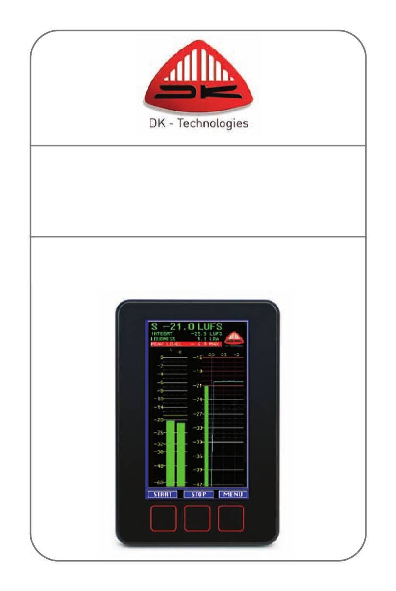
dk 477-200A User manual

20030929 Document no. 477-2010A page 1 of 1
Digital Peak Programme Meter
477-200A
Users Manual

20030929 Document no. 477-2010A page 2 of 2
General Description.
The 477-200 is a customized version of the 478-series of audio level measuring instruments. It is member of a family
of instruments designed to take up the heritage of the previous 477-series PPM´s.
The prime function of this 477-200 series is to measure the peak level of a digital audio signal. Based upon one of
today’s most powerful DSP’s it offers all of its predecessors appreciated qualities like a bright, high definition bar graph
display with a multitude of display modes. In addition to that it provides a platform for realizing new functions like
loudness indication (not implemented) and others not even thought of today. Even though the instrument has been
designed for digital inputs, the various scale designs resembles their analogue counterparts.
It facilitates both measurements with 10/5 ms integration time in accordance with the IEC 268-10 and measurements
with “zero” integration time. Numerous other display functions are available including peak hold, memory, zoom, and
an optional compatibility / phase meter.
The instrument is housed in a ruggedized aluminium cabinet with a high contrast, non-glare scale.
Operating Instructions.
1. GAIN. The scale can be offset by 20 dB to extend the measuring range down to –70
dB. The push button [1] has alternating action and the LED [5] will be lit when GAIN
is selected.
2. FAST. Either “Fast” or normal (5/10ms) integration time may be selected. The sw.1
has an additional MODE function.
Display modes: By holding sw.1 depressed while pressing sw.2 various display modes
(designated “a” to “e” below) are selected sequentially.
a: The mode “a” is easy to distinguish from the rest by the blend-in scale markings. An
illuminated background extends to the scale mark “0” to provide clear scale markings,
even in dimmed light.
b: In mode “b” a spot indication (10 & 11) is provided below the peak reading of the
bar graph. The spot responds to the fastest peaks on the signal (“0” integration time).
The calibration of the spot reading is such that the mark “0” (or the start of “overload
range”) equals digital full-scale level. This means that the distance between the spot
indication and the mark “0” on the shown scale represents the true “head room” before
digital clipping. This means that even with an analogue type scale and 10ms
integration time the true digital peak level can be monitored.
c: In mode “c” a spot will have a “peak hold” action. Otherwise the function is equal of
that of mode “b”.
d: In mode “d” the spot displays the content of the peak memory. The spot appears
either as a dark spot in the bar or as a bright spot in the background above the bar. The
spot is calibrated such that the upper end of the background illumination corresponds
to digital full-scale level.
e: In mode “e” the illuminated background extends to the top of the scale and the spot
acts as a peak hold indication “riding” on the top of the bar. The integration time is the
same as the one selected for the bar.
3. ZOOM. The zoom function will increase the display resolution by a factor of ten.
Thus for the shown scale the –50 mark will represent –5dB and the +5 mark will
represent +0,5 dB. The LED 5 “GAIN” will flash as a warning in this mode.
4. MAX. The meter facilitates a peak memory that continuously stores the highest peak
(since last clear). The stored level may be displayed by pressing the MAX button (4).
The memory can be cleared by pressing 3&4 simultaneously.
5. Gain LED. See point 1
6. FAST LED. See point 2.
7. Sample rate indication.
8. Sample rate indication. When both LEDs are lit it indicates an “unusual” sample rate
i.e. 32kHz or 96 kHz.
9. EMP. The emphasis LED will be lit if the emphasis bit is set in the received digital
signal. No de-emphasis will be introduced to the measured audio level whether the
emphasis bit is set or not.
10.See display modes, “b”
11.See display modes, “b”
12. Phase indication. (Compatibility). On some models only.
GAIN
GAIN
CLRMODE
DC
0+1-1
OL OL
FAST ZOOM MAX
FAST
32
44 48
5
5
10
15
20
25
30
40
50
0
EMP
1234
5
6
7
8
9
10
11
12
13 14 15

20030929 Document no. 477-2010A page 3 of 3
13. DC-warning. Any DC content in the audio signal is deliberately filtered out and will not affect the reading. The
DC LED will however indicate if abnormal DC levels are present in the audio signal.
14. Overload LED. Overload indication, left channel.
15. Overload LED. Overload indication, right channel.
NOTE: On some versions the buttons 1-4 have been omitted for simplicity reasons.
Instrument set-up.
Numerous parameters (like ref. level etc.) may be set by means of the four buttons on the front.
Normally the standard parameters set by the factory will be satisfactory and therefore no adjustments are needed.
Any adjustment should be done by skilled personnel following the instructions below.
In the following the buttons are referred to by numbers (1,2,3,4) where “1” is the leftmost button (or upper on horizontal
scales). Press button 1 is written: [1]. Two buttons may be pressed simultaneously i.e. [1+3].
Adjustment of reference level:
1. Press [1+3] and hold for more than 1.6 s. The display will be lit in both channels with markings pr. 1 dB.
2. Press [3] to decrease reference level in 1 dB steps. Scale max. equals digital FS.
3. Press [4] to increase reference level in 1 dB steps. Scale max. equals digital FS.
4. Press [1] to save settings and resume to normal operation. (Or press [2] to jump to next adjustment point 2)
Activating / deactivating display ballistics:
1. Press [1+3] and hold for more than 1.6 s. The display will be lit in both channels with markings pr. 1 dB.
2. Press [2]. The display will be lit in the left channel with markings pr. 1dB.
3. Press [2]. The display will be lit in the right channel with markings pr. 1sample.
4. Press [2]. The left overload LED will be lit.
5. Press [3] or [4] to toggle display ballistics on/off. Ballistics is on when the right overload LED is lit.
6. Press [1] to save settings and resume to normal operation.
Compensation for “ghost” spot. (Only required if display is replaced.
1. Press [1+3] and hold for more than 1.6 s. The display will be lit in both channels with markings pr. 1 dB.
2. Press [1] and hold for more than 6 s. All LED’s are lit in sequence for inspection.
3. Press [2] The display will be lit in both channels with a falling spot in the right channel.
4. Press [3] if a bright “ghost” of the spot appears in the left channel.
5. Press [4] if a dark “ghost” of the spot appears in the left channel.
6. Press [1] to save settings and resume to normal operation.

20030929 Document no. 477-2010A page 4 of 4
Terminal connections.
Digital (AES3) input and output.
XLR – female XLR - male.
1. Screen 1. Screen
2. Digital input + 2. Digital output +
3. Digital input - 3. Digital output -
The XLR – male connector facilitates a passive loop-through of the AES signal to other apparatus. Hence the
instrument is fitted with a switch able input termination. If the loop-through output is not being used, the switch
(positioned between the two connectors) should be in the 110 Ώposition.
Power connector.
Power is supplied through the coaxial low voltage socket. A mating connector should have an outher diameter of
5.5mm and a hole diameter of 2.1mm. Either a 24V dc or a 18V ac sypply should be used.
Remote Control.
Remote control and additional power connection is accessible through the 9pole male D-sub connector on the rear side.
Pin connections:
1 Remote control #1 (RC#1)
2 Power input (24V dc or 18V ac)
3 Supply GND
4 Remote control #3 (RC#3)
5 Overload indication output.
6 Remote control #2 (RC#2)
7 Supply GND
8 Power input (24V dc or 18V ac)
9 Remote control #4 (RC#4)
PUSH
12
3
1
3
2

20030929 Document no. 477-2010A page 5 of 5
Remote Control.
All the functions of the front buttons are available through the 9pole D connector remote control connector.
Previous users of the NTP477-series instrument will find the same possibilities in this 477-100 series although the
needed external connections have changed.
In addition to the remote control of operating functions (i.e. ”Disp. Peak”), also a number of operating parameters (i.e.
ref. level) can be programmed externally.
Restricting the number of control inputs to just four prohibits the use of simple external on/off connections. Instead
specific resistance values must be used in series with the external switches/connections. The switches “common side”
must all be connected to GND (Pin 4).
Remote Control input 1 (RC#1)
This input facilitates an alternative way of controlling the PPM reference level. If this input is left open the reference
level is set as described under Operating Parameter Settings . If however a resistor is connected to 0V the preset
reference level will be overruled. The resistor value required to obtain a given reference level can be found in table 1. It
may be necessary to use resistors in parallel or series to obtain a specific value to within +/-2%
Table 1.
Reference Resistor Reference Resistor
level value (ohms) level value (ohms)
Reserved 0 -16 dB FS 10625
0 dB FS 313 -17 dB FS 12000
-1 dB FS 645 -18 dB FS 13571
-2 dB FS 1000 -19 dB FS 15385
-3 dB FS 1379 -20 dB FS 17500
-4 dB FS 1786 -21 dB FS 20000
-5 dB FS 2222 -22 dB FS 23000
-6 dB FS 2692 -23 dB FS 26667
-7 dB FS 3200 -24 dB FS 31250
-8 dB FS 3750 -25 dB FS 37143
-9 dB FS 4348 -26 dB FS 45000
-10 dB FS 5000 -27 dB FS 56000
-11dB FS 5714 -28 dB FS 72500
-12 dB FS 6500 -29 dB FS 100000
-13 dB FS 7368 -30 dB FS 155000
-14 dB FS 8333 -31 dB FS 320000
-15 dB FS 9412 Preset level N.C.
Remote Control input 2 (RC#2)
This input is reserved for controlling the reference level loudness mode. (Not implemented in this version)
Remote Control input (RC#3) is reserved for future use.

20030929 Document no. 477-2010A page 6 of 6
Remote Control input 4 (RC#4)
This input is designed to substitute all the functions also accessible as push buttons on the front of the instrument. The
remote switches must have momentary action and a series resistor according to table 3 must be used.
The switches “common side” must all be connected to GND (Pin 3).
Table 3 Function Resistor
value (ohms)
Additional Gain 0
Integration time. Fast/Normal 645
Mode 1379
Zoom 2222
Display max. 3200
Clear max. 4348
Technical specifications.
Supply voltage...................................................................... 20-32 V dc or 18V ac
Current consumption, @ 24V supply...................................160 mA typ. (Max. 220 mA)
Signal input:
Input type .............................................................................Serial digital audio interface (IEC 958/AES3)
Input impedance................................................................... High impedance, floating, (Zi > 1 kΩ) or 110 ohms
Minimum input signal ..........................................................Vmin = 200 mV, Tmin = 0.5 x Tnom (IEC 958)
Sampling rates......................................................................48 kHz, 44.1 kHz and 96 kHz
Measuring characteristics:
Main reading (bar graph):
Integration time ....................................................................5/10 ms (IEC 268-10, 1991-03)
Return time...........................................................................1.7 s ±0,3 s (0 to - 20 dB) (IEC 268-10, 1991-03)
Reference level ....................................................................selectable 0 to 31 dB below max. digital code.
Overload indication .............................................................the bar intensity is increased within overload range.
Low frequency cut-off ......................................................... DC-blocking; Cut-off frequency <0.3 Hz
Secondary reading (spot):
Integration time ...................................................................."zero"
Return time...........................................................................1.7 s ±0,3 s (0 to - 20 dB) (IEC 268-10, 1991-03).
Scale max. ...........................................................................Scale max. equals the lower limit of intensified bar range.
Reference level ....................................................................Scale max. corresponds to max. digital code level.
Phase indication:(option) ....................................................0 to 180°. - Resolution: 18°.
Additional functions:
Gain: Additional 20 dB gain selectable on front.
Mode The Bar-Graph display can be operated in various modes. Pls. refer to the “Operating instructions”
Memory: A peak memory is provided. Reset is controlled from a push-button on the front.
Zoom: To enable extremely accurate reading around "0 dB", the scale may be expanded by a factor of 10.
LED Indicators:
Flashing LEDs on top of each bar for instantaneous digital overload.
Excessive DC-content in either channel.
Gain, when selected.
Sampling rate and preemphasis, if present.
Remote overload indication.
Output for remote overload indication is accessible through the 9-pole D-sub connector. The output is an open collector
in series with an internal 2.2 k Ωresistor. The output is common to both channels.
Table of contents
Other dk Measuring Instrument manuals