DKSH LabPRO 2ml User manual

USER’S
GUIDE
MICROPIPETTE

BIOTIX COBRA PIPETTE
2
Contents Page
1- INTRODUCTION 3
2- PARTS CHECK LIST 3
3- DESCRIPTION 4
4- SETTING THE VOLUME 6
5- USER ADJUSTMENT 7
6- PIPETTING 8
7- GENERAL GUIDELINES FOR GOOD PIPETTING 10
8- ACCESSORIES 12
9- GLP FEATURES 12
10- TROUBLESHOOTING 13
11- LEAK TEST 14
12- MAINTENANCE 15
13- CLEANING AND STERILIZATION 20
14- SPECIFICATIONS 24
15- SPARE PARTS 25
16- MAINTENANCE & CALIBRATION 30
17- WARRANTY 31

USER’S
GUIDE
3
1 - INTRODUCTION
The LabPRO pipette is an air displacement mechanism
and is used with disposable pipette tips.
This pipette line provides:
• Light and comfortable body
• Low pipetting forces ensuring ergonomics and users’
well-being
• Unique patented Lock/Unlock mecanism for results
you can trust
Eight single channel models cover a volume range from
0.2 µL to 10 mL.
Eight multichannel models (4 x 8-ch and 4 x 12-ch)
cover a volume range from 0.5 µL to 300 µL.
2 - PARTS CHECK LIST
Just take a moment to verify that the following items
are present:
Single models
• LabPRO Pipette,
• User’s Guide,
• Certificate of conformity,
• Calibration Key.
• Tip-ejector extention for 10µl only
Multichannel models
• LabPRO Pipette,
• User’s Guide,
• Ejector spacer for short collar tips (only for multi-
channels models 10 µL),
• Certificate of conformity,
• Calibration key.
USER’S
GUIDE

BIOTIX COBRA PIPETTE
4
3 - DESCRIPTION
For 2µl and 10µl Single channel
models, a tip-ejector extention
is supplied to fit with short tips
models.
To fit the tip-ejector extention:
Slide the extention over the
tip-holder
Push the extention firmly
onto the end of the tip-ejec-
tor until it clicks into place
Single models Multichannel models
Color-coded push-button
Lock/Unlock mecha-
nism & Tip-ejector
button
Handle
Connecting nut
Tip-holder
Ejector clip
Ejector support
Ejector lock
Cover
Tip-ejector
Tip-holders
FIGURE 1
FIGURE 2
VWR®MECHANICAL PIPETTE
Counter

USER’S
GUIDE
5
To remove the tip-ejector extention:
Gently twist the extention
Pull it away from the pipette
Ejector spacer for Multichannel models (X10µl only)
Multichannel models fit with long collar tips. If you use
short collar tips, you might have to insert the ejector
spacer especially indicated for that:
• Remove the tip-ejector, keep both ejector locks de-
pressed; pull the tip-ejector down.
• Insert the broad ejector spacer and click it to the tip-
ejector.
•
To refit the tip-ejector, gently re-insert the tip-ejector
vertically into the rails of the ejector support.
FIGURE 3 Long collar tips Short collar tips
Ejector spacer
The volume of liquid to be aspirated is set using the
volumeter. The digits are colored either black or green
to indicate the position of the decimal point, depending
on the model (see examples below).
4 - SETTING THE VOLUME
USER’S
GUIDE

BIOTIX COBRA PIPETTE
6
MODEL Color of volumeter digits
Black Green Increment
2µl µL 0.01 µL 0.002 µL
10µl to 20µl µL 0.1 µL 0.02 µL
8X-10µl, 8X-20µl
12X-10µl, 12X-20µl µL 0.1 µL 0.02 µL
100µl, 200µl, 8X-200µl, 12X-200µl µL - 0.2 µL
8X-300µl, 12X-300µl µL - 0.2 µL
1000µl 0.01 mL mL 0.002 mL
5000µl 0.01 mL mL 0.002 mL
10 mL mL 0.1 mL 0.02 mL
Lock system:
For trusted results, the volume selection is lockable.
0
7
5
X10µl
7.5 µL
1
2
5
X20µl
12.5 µL
X200µl
1
2
5
125 µL
X300µl
1
2
5
125 µL
Single models Multichannel models
VWR®MECHANICAL PIPETTE
1
5
2µl
1.25 µL
2
0
7
5
10µl
7.5 µL
1
2
5
20µl
12.5 µL
100µl
0
7
5
75 µL
200µl
1
2
5
125 µL
1000µl
0
7
5
0.75 mL
5000µl
1
2
5
1.25 mL
10ml
0
7
5
7.5 mL
First step, unlock the
tip-ejector button by
pushing it up
Second step, the
volume is set by turning
the push button
3 Third step, push down
the tip-ejector button.
The selected volume is locked.
Unlocked
Position

USER’S
GUIDE
7
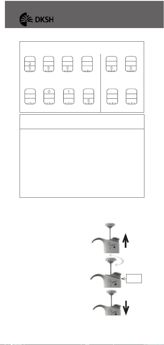
To adjust the volume setting:
Remove the push button.
Use the calibration key to take off the block cover.
a.Insert the metal rod into the
calibration tool on the hexago-
nal side.
b.Engage the two rectangular
hooks of part 2 into the two
holes of the block cover. You
should feel them clipped on
firmly in the hidden part of the
pipette (see figure 5).
c. Make sure to hold the part 1 at the top cap, along
the part 2.
d.Turn the part 2 counterclock-
wise slowly to remove the block
cover (see figure 6).
Put the block cover apart.
To obtain maximum accuracy when setting the volume,
proceed as follows:
>when decreasing the volume setting, slowly reach the
required setting, making sure not to overshoot the mark.
>when increasing the volume setting, pass the required
value by 1/3 of a turn and then slowly decrease to reach
the volume, making sure not to overshoot the mark.
>To adjust perfectly the last digit, it is even more precise
to do so on the Lock position.
The calibration of the LabPRO Pipettes has been per-
formed with distilled water and very high precision
volumetric instruments. Adjusting the pipette can be
necessary for different solutions due to their density,
viscosity, surface tension and/or vapor pressure etc.
Calibration is sometimes recommended when it is used
in high altitudes or with special tips. It can also be reca-
librated when long pipette tips are used. Performance
testing should take place in a draught-free room at 15-
30°C, constant to ± 0.5°C and humidity above 50%.
FIGURE 5
FIGURE 6
Part 1
Part 2
5 - USER ADJUSTMENT
USER’S
GUIDE

BIOTIX COBRA PIPETTE
8
Use the calibration key to adjust
the pipette
a.Insert the metal rod into the
calibration key on the circle tip
side (see figure 7). Lock it into
place. You should feel the in-
ternal part of the calibration key
clamped and clipped on firmly.
If it is not the case, turn it coun-
terclockwise slowly. Then, turn
the plastic connecting nut of the
part 1 slowly until it’s locked in
place (see figure 8).
b.Hold the connecting nut of the
part 1 with one hand
and turn
the part 2 with the other one ac-
cording to the correction needed
(see figure 9).
Once the desired volume
is set, remove the cali-
bration key and put back
the block cover using
the hexagonal side. Turn
it clockwise to lock the
block cover. Put back the
push button.
With reference water, one
revolution (1/8 turn of the
calibration tool) of the vol-
ume setting corresponds to:
Fitting the tips
LabPRO pipettes have been designed to fit universal
tips.
FIGURE 9
Volume range Vol. per 1/8 turn
(equivalence in µL)
2µl 0.012
i.e: 1 full turn is 0.096
10µl 0.047
20µl 0.120
100µl 0.48
200µl 1.20
1000µl 4.75
5000µl 23.8
10ML 48
8X-10µl
12X-10µl 0.058
8X-20µl
12X-20µl 0.120
8X-200µl
12X-200µl 1.20
8X-300µl
12X-300µl 1.90
FIGURE 8
FIGURE 7
6 - PIPETTING

USER’S
GUIDE
9
USER’S
GUIDE
Pre-rinse the tips
Some liquids (e.g.protein-containing solutions and or-
ganic
solvents) can leave a film of liquid on the inside
wall of the tip; pre-rinse the tip to minimize any errors
that may be related to this phenomenon.
Pre-rinsing consists of aspirating the first volume of
liquid and then dispensing it to waste. Tips will not fall
off nor will they have to be manually positioned.
Make sure first that the pipette is calibrated with the
tips that you are using. Then, subsequent volumes that
you pipette will have levels of accuracy and precision
within specifications. Using other tips may require a
validation of the pipetting system.
Aspirate
Press the push-button to the first stop (this corre-
sponds to the set volume of liquid).
Hold the pipette vertically and immerse the tip in the
liquid (see immersion depth table, page 10).
Release the push-button slowly and smoothly (to
top position) to aspirate the set volume of liquid.
Wait one second (time depends on model, see table
page 10); then withdraw the pipette tip from the
liquid.
1st stop
2nd stop
Figure 10

BIOTIX COBRA PIPETTE
10
You may wipe any drop lets away from the outside
of the tip using a medical wipe, however if you do so
take care to avoid touching the tip’s orifice.
/ For the multichannel models, use a reagent reservoir.
Dispense
Place the end of the tip against the inside wall of the
recipient vessel (at an angle of 10° to 40°).
Press the push-button slowly and smoothly to the
first stop.
Wait for at least a second, then press the push-button
to the second stop to expel any residual liquid from
the tip.
Keep the push-button pressed fully down and (while
removing the pipette) draw the tip along the inside
surface of the vessel.
Release the push-button, smoothly. Eject the tip by
pressing firmly on the tip-ejector button.
/ For the multichannel models, use a reagent reservoir.
7 - GENERAL GUIDELINES FOR GOOD
PIPETTING
Make sure that you operate the push-button slowly
and smoothly.
When aspirating, keep
the tip at a constant
depth below the sur-
face of the liquid (re-
fer to the table).
Change the tip before
aspirating a different
liquid, sample, or re-
agent.
Change the tip if a
droplet remains at the
end of the tip from the
previous pipetting op-
eration.
Model Immersion Wait Time
Depth (mm) (seconds)
2µl 1 1
10µl 1 1
20µl 2-3 1
100µl 2-4 1
200µl 2-4 1
1000µl 2-4 2-3
5000µl 3-6 4-5
10mL 5-7 4-5
8X-10µl, 12X-10µl 1 1
8X-20µl, 12X-20µl 2-3 1
8X-200µl, 12X-200µl 2-3 1
8X-300µl, 12X-300µl 2-4 1
Table Immersion Depth and Wait Time

USER’S
GUIDE
11
Each new tip should be pre-rinsed with the liquid to
be pipetted.
Liquid should never enter the tip-holder; to prevent
this:
•
press and release the push-button slowly and
smoothly,
• never turn the pipette upside down,
•
never lay the pipette on its side when there is liquid
in the tip.
If you use the same tip with a higher volume, pre-
rinse the tip.
For volatile solvents you should saturate the air-
cushion of your pipette by aspirating and dispensing
the solvent repeatedly before aspirating the sample.
When the pipetted liquid is not at room tempera-
ture, pre-rinse the tip several times before use.
You may remove the tip-ejector (see chapter 12 -
Maintenance) to aspirate from very narrow tubes.
After pipetting acids or other corrosive liquids that
emit
vapors, remove the tip-ejector, the tip-holder,
rinse, dry
and lubricate the piston (see chapter 12 -
Maintenance).
Do not pipette liquids having temperatures above
70°C or below 4°C. The pipette can be used between
+4°C and +40°C but the specifications may vary ac-
cording to the temperature (refer to the ISO8655-2
standard for conditions of use).
/ Pipettes should be held in the vertical position.
8 - ACCESSORIES
To avoid the possibility of liquid running back into the
pipette, store the pipette vertically.
USER’S
GUIDE

BIOTIX COBRA PIPETTE
12
To identify or personalize your pipette, identification
clips are available:
Identification clips (mixed colors set of 10) FE07060
Identification clips (red, set of 10) FE07061
Identification clips (yellow, set of 10) FE07062
Identification clips (green, set of 10) FE07063
Identification clips (blue, set of 10) FE07064
Identification clips (white, set of 10) FE07065
The Serial Number is engraved
on the body of the pipette. It
provides a unique identification
of the pipette and the manufac-
turing date. Example: 15A1425
To know the specific details
about your pipette, see thetable.
The Bar Code on the box and the
certificate of conformity provide
traceability of your pipette.
Year /CODE Month/CODE NUMBER
(example)
2015/15 January/A 0001
2016/16 February/B 0325
2017/17 March/C 0500
2018/18 April/D 0750
2019/19 May/E 1000
2020/20 June/G 1300
2021/21 July/H 1600
2022/22 August/J 2000
2023/23 September/K 2400
2024/24 October/L 2600
2025/25 November/M 2800
2026/26 December/N 3000
9 - GLP FEATURES
10 - TROUBLESHOOTING
A quick inspection of the pipette may help you to detect
a problem.
The following tables may help you to identify and correct
the problem you might encounter.
For any other symptom or if you can’t solve the problem,
please contact your supplier.
FIGURE 12

USER’S
GUIDE
13
For single models
Symptom Possible Cause Action
Pipette is leaking sample Damaged tip-holder Replace the tip-holder
Worn O-ring or seal Replace both parts and lubricate
Pipette won’t aspirate Worn O-ring Replace both parts and lubricate
Damaged tip-holder Replace the tip-holder
Connecting nut is loose Tighten connecting nut
Damaged or corroded piston Return pipette to supplier
Improper repair or assembly See Chapter 12 - Maintenance
Pipette is inaccurate Improper repair or assembly See Chapter 12 - Maintenance
Unscrewed tip-holder Tighten connecting nut
Connecting nut is loose Tighten connecting nut
Pipette is not precise Tip-holder is loose Tighten connecting nut
Connecting nut is loose Tighten connecting nut
Incorrect operator technique Operator training
Damaged or corroded piston(s) Return pipette to supplier
Damaged tip-holder(s) Replace the tip-holder
Worn O-ring or seal Replace both parts and lubricate
Tips fall off or do not Low quality tips
Use good quality tips to hav
e
opti
-
fit correctly
mum results of the pipetting system
Dirty tip-holder Clean the tip-holder with
isopropanol or ethanol
Damaged tip-holder(s) Replace the tip-holder
Damaged tip-ejector Replace tip-ejector
The tip-ejector is loose
Assemble the tip-ejector properly
The ejector lock is misaligned Align the ejector lock
Pipetting seize up Piston need lubricant Lubricate piston assembly
For Multichannel models
Symptom Possible Cause Action
Tips fall off or Low quality tips
Use good quality tips to hav
e
opti
-
do not fit correctly
mum results of the pipetting system
Tip-ejector damaged Replace tip-ejector
Ejector spacer damaged Replace ejector spacer
Dirty tip-holder Clean them with ethanol or
isopropanol
Damaged tip-holder Contact your local supplier
Pipette won’t aspirate Connecting nut is loose Tighten connecting nut
Pipette is inaccurate Connecting nut is loose Tighten connecting nut
Pipette is not precise Connecting nut is loose Tighten connecting nut
Incorrect operator technique Operator training
USER’S
GUIDE

BIOTIX COBRA PIPETTE
14
This test may be performed at any
time to check that the pipette does
not leak, especially after perform-
ing a maintenance or sterilization
procedure. If a pipette fails this
test, replace the O-ring and seal.
After making sure that the pipette
is correctly reassembled, repeat
this test.
For the 2µl to 200µl Single channel models:
Fit Pipette Tips.
Set the pipette to the maximum volume given in the
specifications, and pre-rinse.
Aspirate the set volume from a beaker of distilled
water.
Maintain the pipette in the vertical position and wait
for 20 seconds.
If a water droplet appears at the end of the tip there
is a leak.
If you see no droplet, re-immerse the tip below the
surface of water.
The water level inside the tip should remain constant;
if the level goes down there is a leak.
For the 1000µl, 5000µl and 10mL Single channel
models:
Fit Pipette Tips.
Set the pipette to the maximum volume given in the
specifications.
Aspirate the set volume from a beaker of distilled
water.
Maintain the pipette in the vertical position and wait
for 20 seconds.
If a water droplet appears at the end of the tip, there
is a leak.
no leak
FIGURE 14
11 - LEAK TEST

USER’S
GUIDE
15
For the Multichannel models (8X - 12X):
Fit Pipette tips.
Set the pipette to the maximum volume given in the
specifications, and pre-rinse.
Aspirate the set volume from a reagent reservoir of
distilled water.
Maintain the pipette in the vertical position and wait
for 20 seconds; fluid level in tips should remain con-
stant.
If a water droplet appears at the end of the tip, there
is a leak.
If you see no droplet, for volumes below 200 µL, re-
immerse the tip below the surface of water.
The water level inside the tip should remain constant;
if the level goes down there is a leak.
12A - MAINTENANCE FOR THE SINGLE
CHANNEL MODELS ONLY
Routine maintenance will help to keep your pipette in
good condition, ensuring a continued high level of per-
formance.
Maintenance is limited to:
• Cleaning or sterilization (see Chapter 13 - Cleaning
and Sterilization).
• Replacing spare parts.
• Greasing the piston assembly.
Lubricant tube 1 g is available under the reference
FE07066
2µl and 10µl Single channel models should not be
disassembled, so you may only replace the push-
button, tip-ejector and its adapter.
With these pipettes if the tip-holder is damaged, the
piston may also be damaged.
USER’S
GUIDE

BIOTIX COBRA PIPETTE
16
Changing the tip-ejector
To remove
Push the ejection button.
Push laterally (to the left) the
tip-ejector.
Slide and remove the tip-ejector.
To refit
Push the ejection button.
Slide the tip-ejector along the
tip-holder.
Clip and push laterally (to the right) the tip-ejector
on the body of the pipette.
Changing the tip-holder – no tools required
Remove the tip-ejector (see above).
Unscrew the connecting nut by turning it clockwise.
Carefully separate the lower and upper parts.
Remove the piston assembly and the seals.
Clean, sterilize, or replace the tip-holder.
If necessary, lubricate lightly the piston and its seals
(see below).
Reassemble the pipette (refer to the figure 16).
Tighten the connecting nut (turn counterclockwise).
Refit the tip-ejector (see above).
Servicing the piston assembly
You may remove the piston assembly for cleaning pur-
poses only. If the piston assembly is changed, the pi-
pette must be adjusted and calibrated in the Supplier
Service Center. As the models 2µl and 10µl single
channel models contain miniaturized parts, it is best
not to disassemble these pipettes yourself.
Remove the tip-ejector (see above).
Unscrew the connecting nut by turning it clockwise.
Carefully separate the lower and upper parts.
Remove the piston assembly, O-ring and seal.
FIGURE 15

USER’S
GUIDE
17
Leave exposed the piston, clean it with isopropanol
or ethanol and lubricate lightly.
For 20µl, 100µl, 200µl Single channel models:
lubricate only the useful part of the piston
(20 ±5 mm length) and the O-ring.
For 1000µl single channel model:
lubricate the piston.
For 5000µl, 10mL single channel model:
disassemble the seals, lubricate their internal part
and lubricate the piston. Do not lubricate the O-ring.
Reassemble the pipette (refer to the figure 16).
Tighten the connecting nut (turn counterclockwise).
Refit the tip-ejector (see above).
Changing the seals
The O-ring and seal are on the piston; if worn or dam-
aged in any way (chemical or mechanical), they must be
replaced. As the models
2µl and 10µl single channel
models
contain miniaturized parts, it is best not to
disassemble these pipettes yourself, please contact
your Supplier Service Center.
The dimensions of the O-ring vary depending on the
model of pipette.
Remove the tip-ejector (see above).
Unscrew the connecting nut by turning it clockwise.
Carefully separate the lower and upper parts.
Remove the piston assembly, O-ring and seal.
If necessary clean the piston and replace the seal ;
lubricate them lightly. Please place them in the cor-
rect order.
Reassemble the pipette (refer to the figure 16).
Tighten the connecting nut (turn counter clockwise).
Refit the tip-ejector (see above).
12B - MAINTENANCE FOR THE MULTI-
CHANNEL MODELS ONLY
USER’S
GUIDE

BIOTIX COBRA PIPETTE
18
FIGURE 16
Tip-ejector Tip-holder
Connecting nut
Color-coded push-button
(volume setting)
20µl
100µl
200µl
Piston assembly
1000µl
5000µl
10mL

USER’S
GUIDE
19
Routine maintenance will help keep your pipette in good
condition,ensuring acontinuedhighlevelof performance.
Maintenance is limited to:
• Cleaning or sterilization (see Chapter 13 - Cleaning
and Sterilization)
• Replacing spare parts
• Greasing the piston assembly.
FIGURE 17
Ejector lock
Tip-ejector
12B - MAINTENANCE FOR THE MULTI-
CHANNEL MODELS ONLY
USER’S
GUIDE

BIOTIX COBRA PIPETTE
20
FIGURE 18
Ejector spacer for
10µl models only
Changing the tip-ejector
To remove the tip-ejector, keep both ejector locks
depressed. Pull the tip-ejector down. To refit the tip-
ejector, gently re-insert the tip-ejector vertically into
the rails of the ejector support. Pull lightly on the tip-
ejector to check the position.
13 - CLEANING AND STERILIZATION
LabPRO Pipettes are designed so that the parts normally
in contact with liquid contaminants, can easily be cleaned
and decontaminated. However, because the models 2µl
and 10µl single channel models contain miniaturized
parts, it is best not to disassemble these pipettes
yourself; please contact your Supplier Service Center.
Liquid must never enter the upper part (handle) of any-
pipette.
Cleaning for the Single Models only
The pipette must be cleaned, as described below, be-
fore it is decontaminated. Soap solution is recommend-
ed for cleaning these models.
External cleaning
Remove the tip-ejector.
Wipe the tip-ejector with a soft-cloth or lint-free
tissue impregnated with soap solution.
This manual suits for next models
10
Table of contents