Viso Systems BaseSpion User manual
VISO SYSTEMS
BaseSpion
User Manual
Revision: 2020-10

2
Congratulations on purchasing your new Viso Systems product. Before using this
product, please read the Safety Information.
This manual contains descriptions and troubleshooting necessary to install and
operate your new Viso Systems product. Please review this manual thoroughly to
ensure proper installation and operation.
For news, Q&A and support at Viso Systems, visit our website at
www.visosystems.com
Other manuals in this series (the latest version can be downloaded from
www.visosystem.com):
▪Guidelines - building a lighting laboratory
▪BaseSpion Assembly Manual
▪LabFlicker User Manual
▪VISO Reference CALI-T50 User guide (calibration light source)

3
Contents
1. Safety Information..............................................................................................................4
1.1. Preventing Electric Shocks ............................................................................................4
2. Disposing of this Product ....................................................................................................4
3. Introduction .......................................................................................................................4
3.1. About this Document....................................................................................................4
3.2. About the BaseSpion.....................................................................................................4
4. Product dimensions............................................................................................................5
5. Packaging and Weight ........................................................................................................6
6. BaseSpion Items .................................................................................................................7
7. Shipping Packages ..............................................................................................................7
8. Room Considerations..........................................................................................................7
8.1. General Laboratory Considerations ..............................................................................7
8.2. Sensor Distance.............................................................................................................7
9. Room and Table Dimensions...............................................................................................8
10. Goniometer ‘Dark Zone’ .....................................................................................................9
11. Installation ....................................................................................................................... 10
11.1. Software Installation...................................................................................................10
11.2. Connect Power............................................................................................................11
11.3. AC Power Supply Cable Plug .......................................................................................11
11.4. Connect USB ...............................................................................................................12
11.5. Connecting the BaseSensor ........................................................................................13
11.6. Connecting the C-plane Goniometer ..........................................................................13
11.7. Connecting Light Source Power ..................................................................................13
11.8. AC Power Supply Cable Plug .......................................................................................14
11.9. Connecting Diagram....................................................................................................14
11.10. Mounting and Alignment of the Light Source.............................................................15
11.11. Center of Luminaires...................................................................................................17
11.12. Mounting of Fixtures with a Static Base .....................................................................18
12. Making Measurements..................................................................................................... 19
12.1. Alignment of the Sensor .............................................................................................19
12.2. Making a Measurement..............................................................................................19
13. Attaching the E27 Lamp Holder......................................................................................... 20
14. Specifications ................................................................................................................... 22
15. Appendix 2: Laboratory Checklist...................................................................................... 24

4
1. Safety Information
Warning! This product is not for household use.
Read this manual before installing and operating the BaseSpion, follow the safety
warnings listed below, and study all the cautions in the manual.
1.1. Preventing Electric Shocks
Make sure the power supply is always grounded.
Use a source of AC power that complies with the local building and electrical codes,
that has both overload and ground-fault protection.
If the controller or the power supply are in any way damaged, defective, wet, or
show signs of overheating, disconnect the power supply from the AC power and
contact Viso Service for assistance.
Do not install or use the device outdoors. Do not spray with or immerse in water or
any other liquid.
Do not remove any covers or attempt to repair the controller or the power supply.
Refer any service to Viso.
2. Disposing of this Product
Viso Systems products are supplied in compliance with Directive 2012/19/EU on
waste - electrical and electronic equipment (WEEE) together with the RoHS Directive
2011/65/EU with amendments 2015/863. Help preserve the environment! Ensure
that this product is recycled at the end of its lifetime. Your supplier can give details of
local arrangements for the disposal of Viso Systems products.
3. Introduction
3.1. About this Document
These guidelines describe the installation process of the BaseSpion followed by the
typical measurements of various light sources.
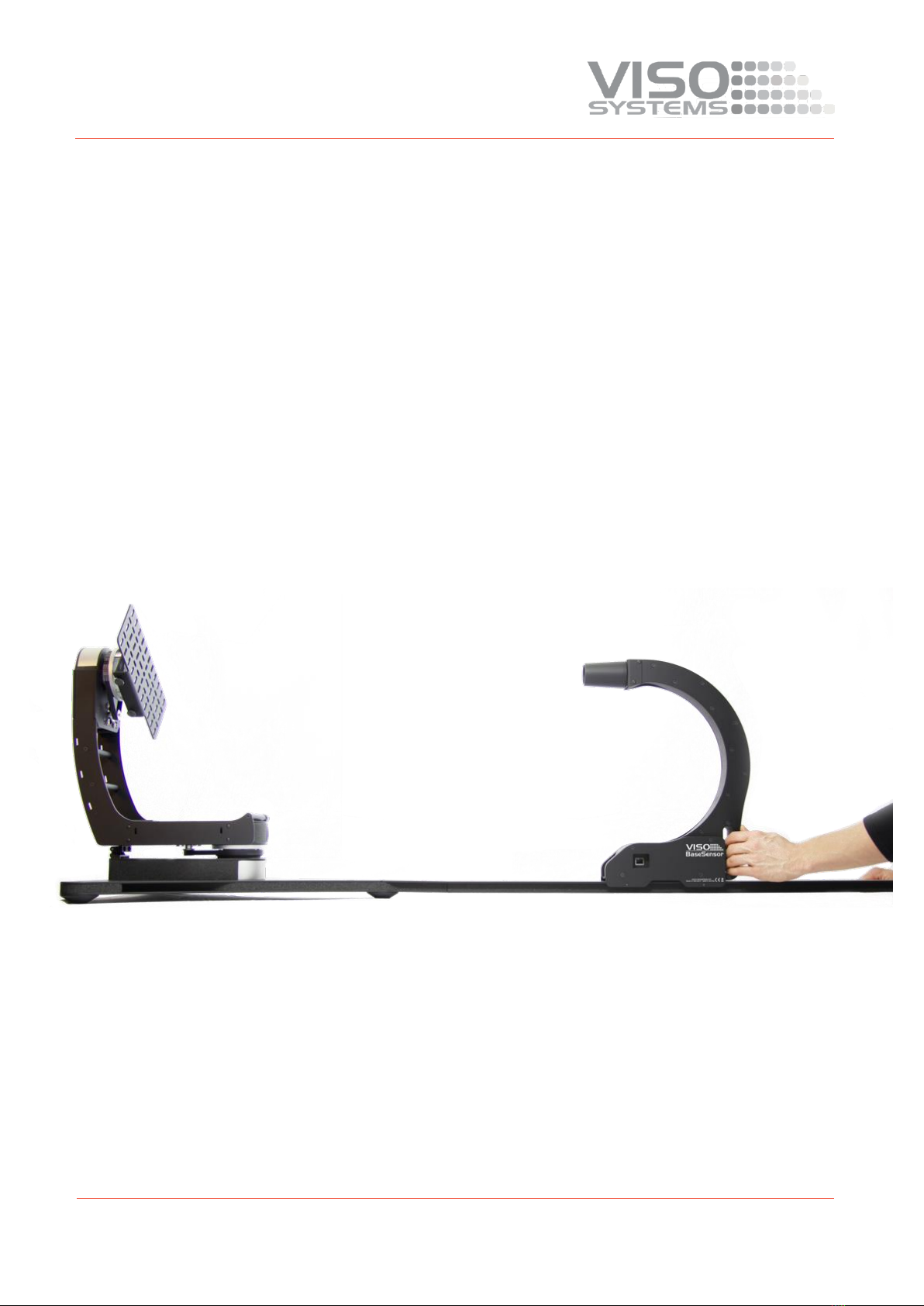
3.2. About the BaseSpion
The BaseSpion is a revolutionary new far field goniometer system with a
spectrometer sensor that makes it possible to measure all photometric
measurements quickly and efficiently. The Light Inspector software enables it to
quickly measure, save and export the newly obtained data.
© 2007 Viso Systems ApS, Denmark
All rights reserved. No part of this manual may be reproduced, in any form or by any means,
without permission in writing from Viso Systems ApS, Denmark. Information subject to change
without notice. Viso Systems ApS and all affiliated companies disclaim liability for any injury,
damage, direct or indirect loss, consequential or economic loss or any other loss occasioned by
the use of, inability to use or reliance on the information contained in this manual.

5
4. Product dimensions
Goniometer
Sensor
Rail I+II+III
517
142
250
548
560
170
109
423
A A
B B
C C
D D
E E
F F
8
8
7
7
6
6
5
5
4
4
3
3
2
2
1
1
DRAWN
CHK'D
APPV'D
MFG
Q.A
UNLESS OTHERWISE SPECIFIED:
DIMENSIONS ARE IN MILLIMETERS
SURFACE FINISH:
TOLERANCES:
LINEAR:
ANGULAR:
FINISH: DEBURR AND
BREAK SHARP
EDGES
NAME
SIGNATURE
DATE
MATERIAL:
DO NOT SCALE DRAWING
REVISION
TITLE:
DWG NO.
SCALE:1:10 SHEET 1 OF 1
A3
WEIGHT:
BaseSpion Base Behind Dimensions
248
280
421
67
A A
B B
C C
D D
E E
F F
8
8
7
7
6
6
5
5
4
4
3
3
2
2
1
1
DRAWN
CHK'D
APPV'D
MFG
Q.A
UNLESS OTHERWISE SPECIFIED:
DIMENSIONS ARE IN MILLIMETERS
SURFACE FINISH:
TOLERANCES:
LINEAR:
ANGULAR:
FINISH: DEBURR AND
BREAK SHARP
EDGES
NAME
SIGNATURE
DATE
MATERIAL:
DO NOT SCALE DRAWING
REVISION
TITLE:
DWG NO.
SCALE:1:5 SHEET 1 OF 1
A3
WEIGHT:
Sensor Assem Dimensions
517
142
250
548
560
170
109
423
A A
B B
C C
D D
E E
F F
8
8
7
7
6
6
5
5
4
4
3
3
2
2
1
1
DRAWN
CHK'D
APPV'D
MFG
Q.A
UNLESS OTHERWISE SPECIFIED:
DIMENSIONS ARE IN MILLIMETERS
SURFACE FINISH:
TOLERANCES:
LINEAR:
ANGULAR:
FINISH: DEBURR AND
BREAK SHARP
EDGES
NAME
SIGNATURE
DATE
MATERIAL:
DO NOT SCALE DRAWING
REVISION
TITLE:
DWG NO.
SCALE:1:10 SHEET 1 OF 1
A3
WEIGHT:
BaseSpion Base Behind Dimensions
6
5. Packaging and Weight
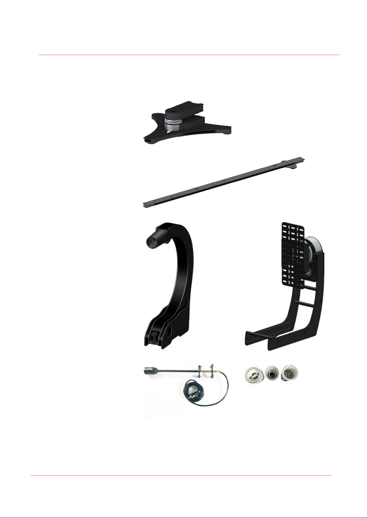
The BaseSpion consist of 5 main assemblies as shown below.
Base –14 kg
2/3 x sensor rail –4 kg (12 kg)
Sensor 4 kg
Tower 4 kg
E27 lamp holder –0,5 kg
E27 Adapters 0,2 kg

7
6. BaseSpion Items
▪Base
▪3 x Sensor rails
▪Tower
▪Sensor
▪Bulb holder with E27, E14, G10 and B22 adaptor.
▪Light Inspector USB stick (Windows)
▪2 m IEC power cord
▪5 m USB cable
▪7,5 m RJ45 cable for connection the Sensor
▪Screws and cables for assembly
7. Shipping Packages
Shipping Packages
Shipping Dimensions
Shipping Volume
Weight
1. Sensor
500 x 500 x 200 mm
0.050 m3
5 kg
2. Base + Tower
600 x 600 x 350 mm
0.126 m3
20 kg
3. Rails + Assemblies
1,650 x 280 x 280 mm
0.129 m3
16 kg
Total shipping weight: 41 kg.
Total shipping CBM: 0.305 m3
The shipment is done in a total of 3 packages.
8. Room Considerations
8.1. General Laboratory Considerations
See Viso publication “Guidelines - building a lighting laboratory”. The most up-to-
date version can be downloaded from www.visosystem.com.
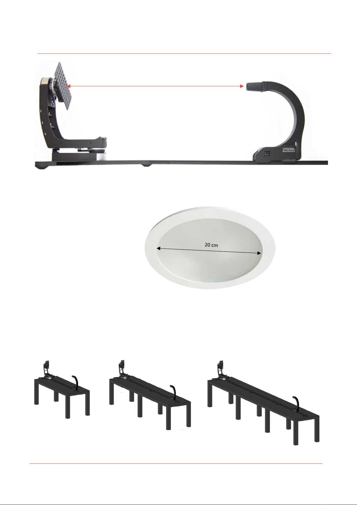
8.2. Sensor Distance
The BaseSpion is a far field system, which means the distance between the light
source and the sensor should be at least 8 x diameter of the lamp as shown below.
8
For example, for a lamp with a 20 cm diagonal illuminating surface, the distance
from center of rotation of the gonio to the sensor should be at least 160cm (20cm x
8). See more in “Guidelines - building a lighting laboratory”.
Note ! The “Lamp diameter” is only the light emitting part of the lamp.
9. Room and Table Dimensions
The Sensor Rail that attaches to the Goniometer Base comes standard in three parts giving you the option of three different setups,
depending on your needs and what your room allows.
Sensor distance =
min. 8 x Lamp
diameter
9
In the chart below is given the max light source size for each rail position.
Rail
position
Light
Source
Diameter
Sensor
Distance
Table
Length
Room
Length
Rail
1
40 mm
350 mm
2 m
3 m
I
2
60 mm
500 mm
2 m
3 m
I
3
90 mm
750 mm
2 m
3 m
I
4
120 mm
1000 mm
2 m
3 m
I
5
180 mm
1500 mm
2 m
3 m
I
6
240 mm
2000 mm
3.5 m
4.5 m
I+II
7
300 mm
2500 mm
3.5 m
4.5 m
I+II
8
360 mm
3000 mm
3.5 m
4.5 m
I+II
9
420 mm
3500 mm
5 m
6 m
I+II+III
10
540 mm
4500 mm
5 m
6 m
I+II+III
Example
If you need to measure a light source with a diameter of 270 mm, you need to have
Rail I and Rail II mounted and the sensor should be slid to position 7 (sensor distance
2500 mm)
Room width: Recommended 100 cm or more (Minimum 60 cm depending on lamp
size)
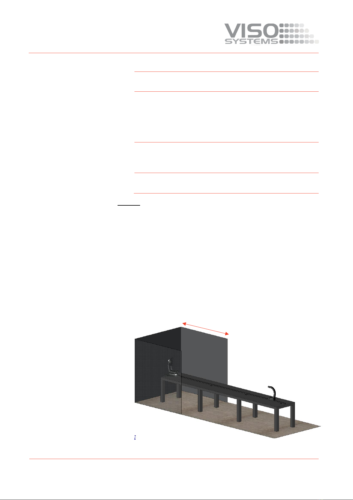
10. Goniometer ‘Dark Zone’
Normally when doing light measurements, a completely dark room is needed. But
with the BaseSpion it is not a necessity for the whole room to be dark as the sensor
uses a special directional sensor. This means having only the goniometer in a dark
zone will be sufficient, as shown below.
Minimum 1 m recommended
Dark Zone

10
It is recommended the depth of the dark zone to be 1 meter or more.
A room can be darkened either by painting the walls black or using a black curtain. A
black molton curtain can be better than a painted wall, as the folds in the curtain
works as small light baffles trapping the light. See more in “Guidelines - building a
lighting laboratory”.
Note: If you have the option to have a fully dark room, this should be your first
choice.
11. Installation
11.1. Software Installation
Before you can start using the BaseSpion, the “Viso Light Inspector” software must
be installed. It is supported on all windows platforms.
Use the following link to download the latest version:
http://www.visosystems.com/download-light-inspector/
1) Please make sure the BaseSpion is not connected to the computer during
software installation.
2) Run the .msi file and follow the installation instruction.

11
3) USB drivers are automatically installed.
Your measurements are not lost when updating to a newer version or uninstalling
and reinstalling. All measurements will always remain in your document folder. If
you want to remove all your measurements go to the ‘Light Inspector’ folder and
delete them manually.
Folder location:
C:\Users\’Username’\Documents\Viso Systems\Light Inspector
Or if stored in dropbox:
C:\Users\’username’\Dropbox
11.2. Connect Power
The BaseSpion comes with a
standard IEC power-in
connector and with a standard
euro power cable, but any
power cable can be used as the
BaseSpion supports any outlet
voltage from 90-260VAC.
The power-in connector
supplies power to the
goniometer motor, power
analyzer and the light source
being measured. Which means
the power feed to the system is
also what is being delivered to
the light source to be measured.
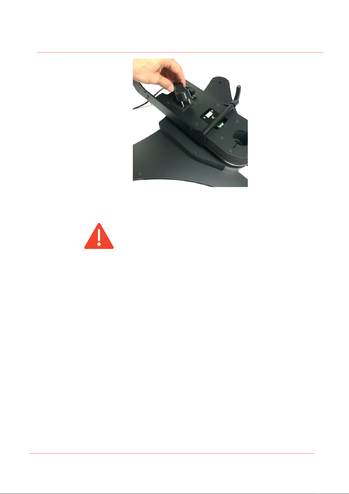
11.3. AC Power Supply Cable Plug
Warning: Risk of an electric shock! Plug installation shall be performed by a qualified
electrician.
A grounding-type (earthed) power plug that fits the local power outlet must be used.
You can acquire an IEC power cable with a suitable grounding-type plug from most of
consumer electronics stores.
When installing the plug connect pins as follows:
▪Yellow and green wire to grounding (earth)

12
▪Blue wire to neutral
▪Brown wire to live
11.4. Connect USB
The BaseSpion is connected
to the computer using a USB
connector type A to B. A 2-
meter USB cable is included
with the BaseSpion,
however any USB cable
supporting USB2.0 can be
used.
The USB provides
communication and power
to the BaseSpion’s main
board processor. But to run
power analyzer and
spectrometer, you need to have power connected.
Start the “Viso Light Inspector” software after having connected the USB; the
connection to the BaseSpion will be established automatically. A successful
connection is shown with a green “Connected” icon in the upper right-hand corner
of the ‘Viso Light Inspector’ software.
You can connect and disconnect the USB without restarting the “Viso Light
Inspector” software, as the connection is always established automatically as soon as
the USB connector is plugged in and vice versa.
Neutral
Ground/Earth
Live

13
11.5. Connecting the BaseSensor
The BaseSpion is
connected to the
LabSensor with a RJ45
cable.
A 7.5-meter RJ45 Cat5
shielded cable is supplied
with the BaseSpion, but
any shielded RJ45 cable
can be used.
Warning: Do not connect the Sensor to the C-plane motor connector, this could
damage the Sensor.
11.6. Connecting the C-plane Goniometer
The C-plane goniometer is connected to the BaseSpion base through a RJ45 cable.
The BaseSpion will automatically detect the C-plane goniometer.
Warning: Do not connect the C-plane motor to the Sensor connector. This could
damage the BaseSpion.
11.7. Connecting Light Source Power
The BaseSpion has a built-in power analyzer and power switch. The power switch is
used when running in ambient light correction mode. So the lamp can be switched
off before a measurement, so that the values of the ambient light can be obtained
and subsequently subtracted from final measurements.
14
The maximum current supported by the lamp output is 3A, which is 660 W at 220
VAC and 330 W at 110 VAC.
11.8. AC Power Supply Cable Plug
Warning: Risk of electric shock! Plug installation shall be performed by a qualified
electrician.
A grounding-type (earthed) power plug that fits the local power outlet must be used.
You can acquire an IEC power cable with a suitable grounding-type plug from most of
consumer electronics stores.
When installing the plug connect pins as follows:
▪Yellow and green wire to grounding (earth)
▪Blue wire to neutral
▪Brown wire to live
Good light measurements rely on stable main supply. If mains supply is insufficient
the light source can be supplied via an external power supply. Se more in the Light
Inspector software manual.
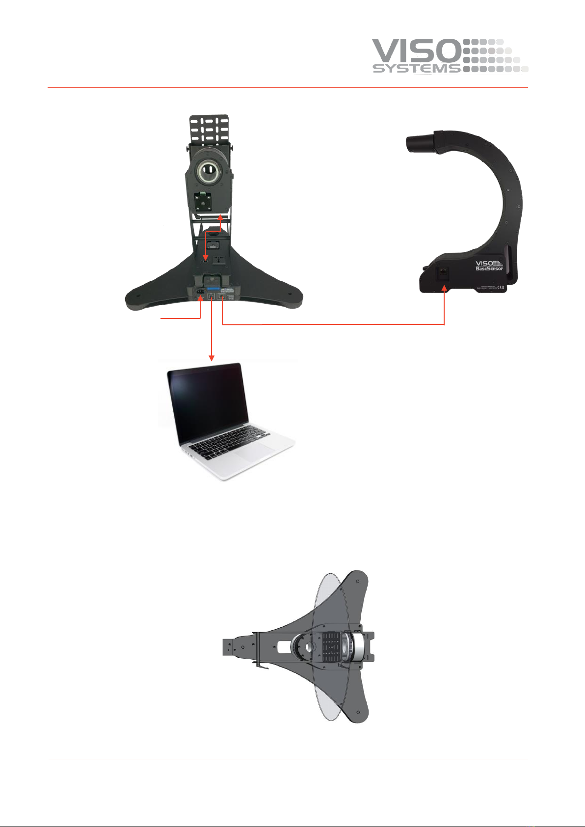
11.9. Connecting Diagram
Below there is the connection diagram showing the different connections in order to
make the system operational.
15
11.10. Mounting and Alignment of the Light Source
Aligning the lamp is key to ensuring a precise measurement. Cut outs in the top of
the goniometer marks the center of rotation. Any lamp must carefully centered
before measurement, like the picture below. The transparent disc imitates the
center of a lamp.
USB
RJ45 –CAT5 Shielded
90-260 VAC
RJ45 –CAT5

16
The tower can be adjusted from 0cm to a max lamp depth of 35 cm.
Min. Max.
17
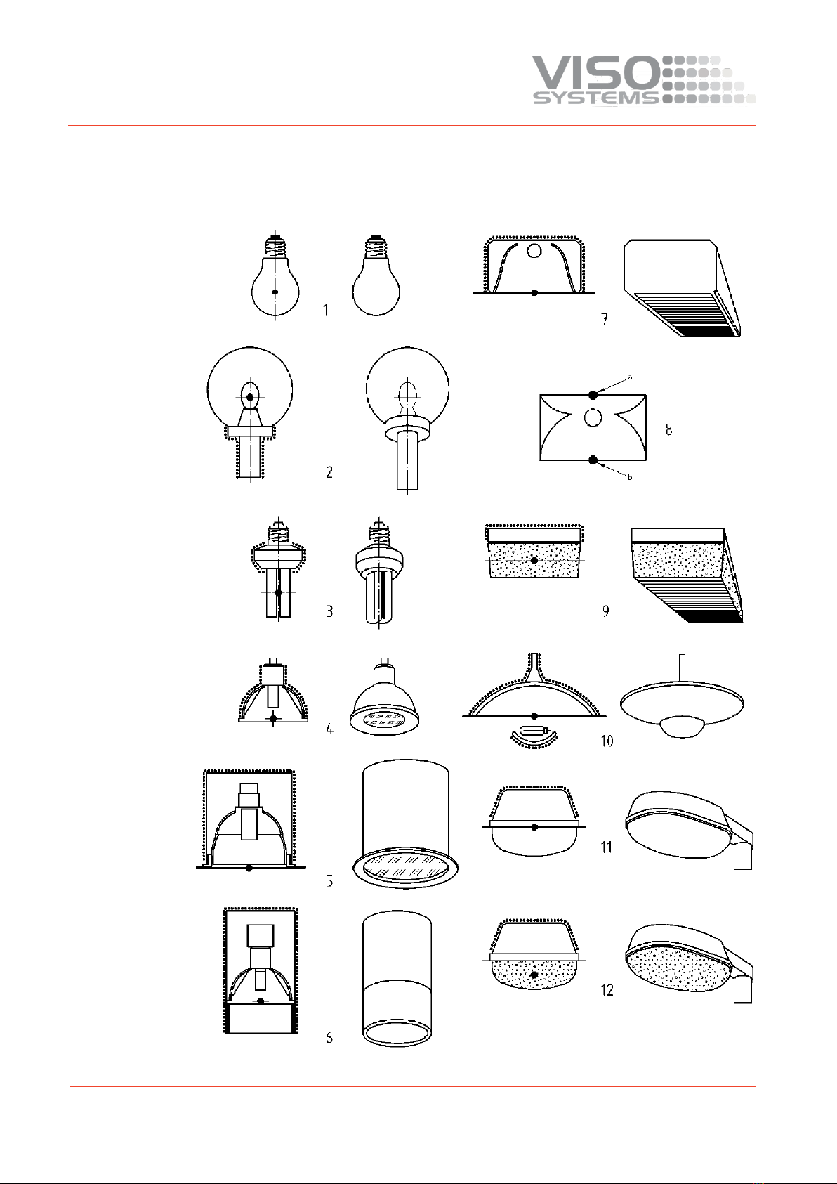
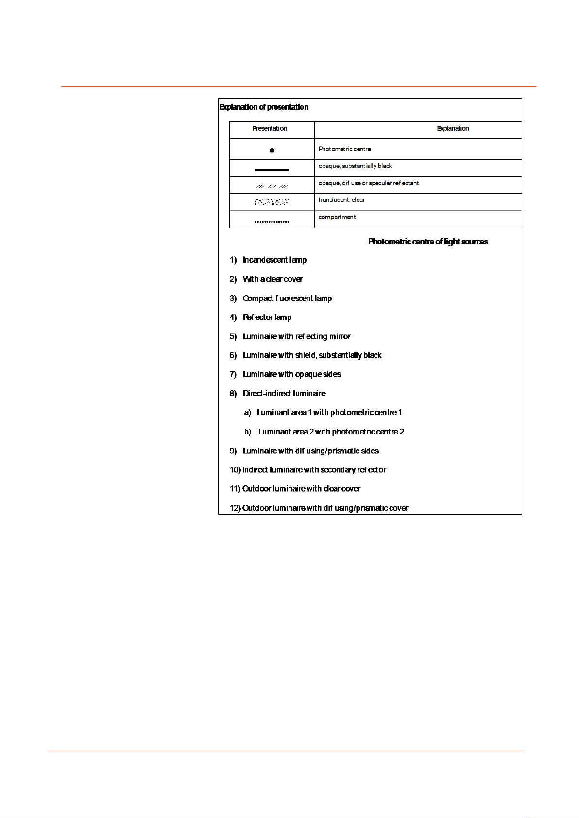
11.11. Center of Luminaires
The black spot marks the photometric center of the different lamps (EN 13032-
1:2004). This photometric center is what should be aligned with center of rotation of
the Base.
18
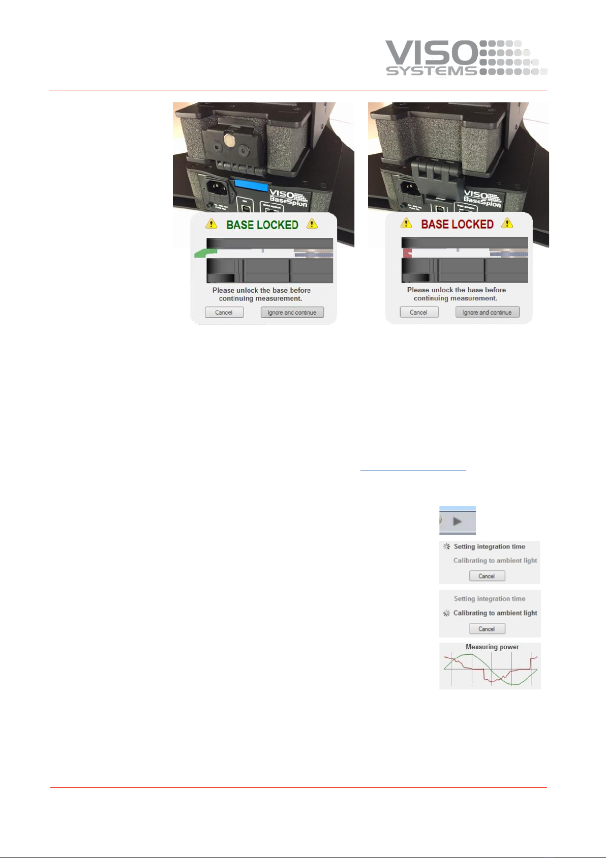
11.12. Mounting of Fixtures with a Static Base
To keep the BaseSpion goniometer still, when mounting and aligning a light source
for measurement there is a lock on the back of the goniometer.
A sensor detects when the base is locked and if a measurement is started with the
lock activated an animated message will appear in the software, reminding you to
unlock the base before continuing.
19
12. Making Measurements
12.1. Alignment of the Sensor
Before making any measurements, it is important to place the sensor at an
appropriate distance. The BaseSpion is a far field goniometer system, which means
that the distance between the sensor and the lamp should be equal to or larger than
eight times the lamp length/diameter.
Further info, see Installation Chart, Section 8.2, Sensor Distance.
12.2. Making a Measurement
1
A measurement is simply started by clicking on
the play icon on the menu bar
2
Then the integration time is set automatically
3
The ambient light level is automatically
measured by turning off the light source
4
The power is then measured and stored
5
The light source is then rotated at 180 degrees
to prepare for measurement

20
6
The complete 360 degrees angular light field is
then measured and the beam angle is
calculated
For an in-depth walkthrough of the Light Inspector software, go to the ‘Light
Inspector Manual’
13. Attaching the E27 Lamp Holder
Loosen the brass bolt at the end
Put cable plug, brass bolt and the small loose bracket through the C-Plane head
Other manuals for BaseSpion
1
Table of contents
Other Viso Systems Laboratory Equipment manuals


