Designed, engineered, and
manufactured in Springfield, MO
using U.S. and global components.
LT-1823 1.01 21062
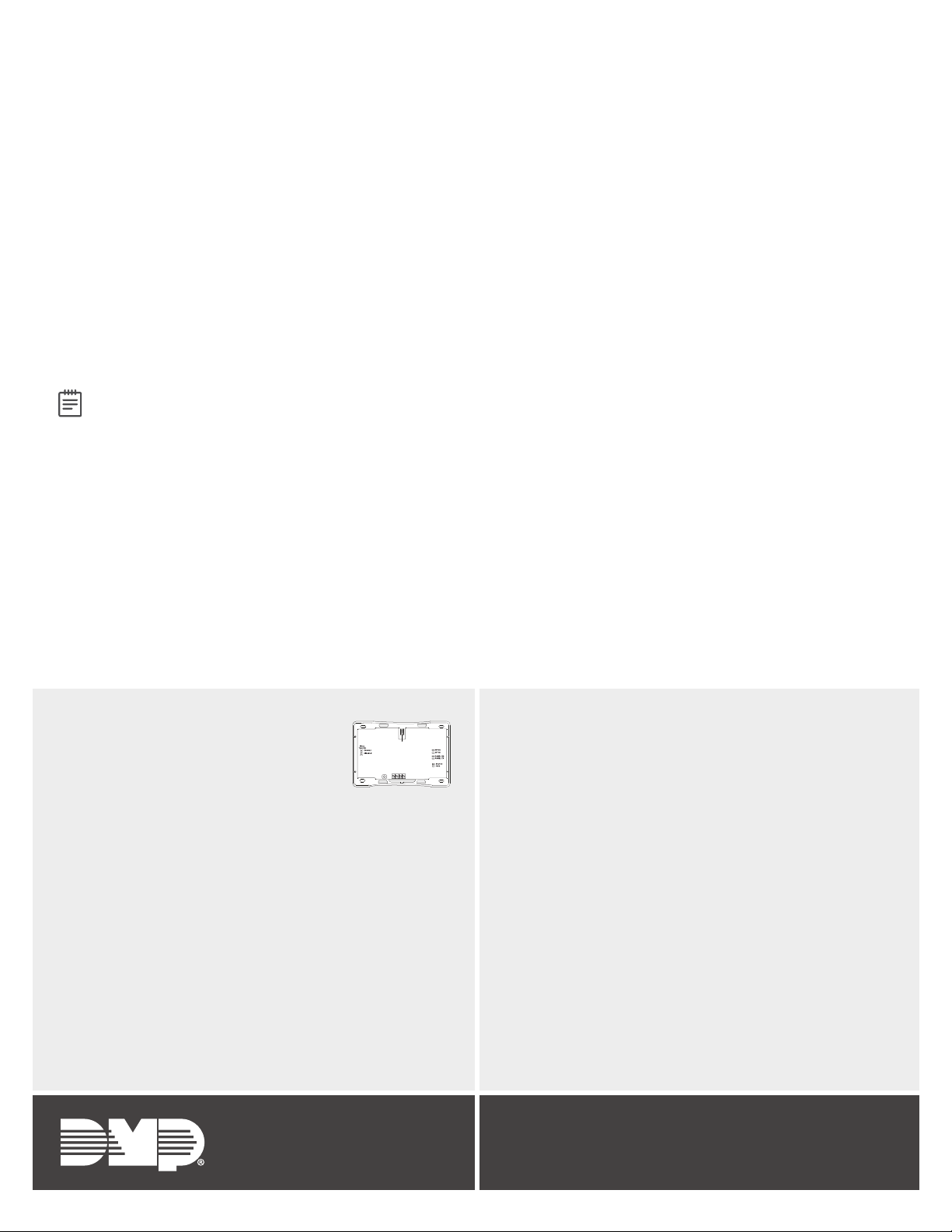
1100XH SERIES
HIGH POWER WIRELESS
RECEIVER
Specifications
Operating Voltage 12VDC Nominal
Current Draw 75mA (average), 102mA (peak)
Frequency Range 905-924MHz
Housing Dimensions 5.5”W x 3.75”L x 1”H
Housing Color White
Housing Material Flame Retardant ABS
Patents
U.S. Patent Number 7, 239, 236
Ordering Information
1100XH-W Standard Wireless Receiver
1100XHE-W Encrypted Wireless Receiver
Certifications
California State Fire Marshal (CSFM)
New York City 1100 Series Wireless (FDNY COA #6167)
INTRUSION • FIRE• ACCESS• NETWORKS
2500 North Partnership Boulevard
Springfield, Missouri 65803-8877
800.641.4282 | DMP.com
© 2021
FCC Part 15: CCKPC0114R6
CCKPC0114R9
Industry Canada: 5251A-PC0114R6
5251A-PC0114R9
Underwriters Labratory (UL) Listed
• ANSI/UL 365 Police Station Connected Burglar
• ANSI/UL 609 Local Burglar Alarm Units & Systems
• ANSI/UL 864 Fire Protective Signaling Systems
• ANSI/UL 985 Household Fire Warning Systems
• ANSI/UL 1023 Household Burglar Alarm System Units
• ANSI/UL 1076 Proprietary Burglar Alarm Units
• ANSI/UL 1610 Central Station Burglar Alarm Units
Compatible With Devices Listed for:
• ANSI/UL 268 Smoke Detectors for Fire Alarm Signaling
Systems
• ANSI/UL 521 Heat Detectors for Fire Protective Signaling
Systems
• ANSI/UL 634 Connections and Switches for use with Burglar
Alarm Systems Accessory
• ANSI/UL 636 Safety Holdup Alarm Units and Systems
• ANSI/UL 639 Intrusion Detections Units Accessory
• ANSI/UL 2075 Gas and Vapor Detectors and Sensors
For applications that must conform to a National Recognized Testing Laboratory certified system, read the information
below for additional information.
Commercial Fire
Transmitters must be programmed as supervised. Refer to Table 3 for specific supervision times. The maximum line
impedance of the 4-wire bus is 16.2 Ohms for 1, 000 feet (305 meters). The recommended wire gauge for panel to
receiver connection is 22 AWG.
After all transmitters are in position, the WLS option of the panel’s Walk Test must be operated and all transmitters
programmed for Fire (FI) or Supervisory (SV) must show that their check-in message was received. Refer to the panel
programming guide for Trip Counter for DMP Wireless Check-in Test (WLS) which describes that both numbers of the
counter must match. If not and a failed wireless zone is displayed at END, decrease that transmitter’s range with the
receiver and perform the Wireless Walk Test again.
LISTED COMPLIANCE SPECIFICATIONS
FCC INFORMATION
This device complies with Part 15 of the FCC Rules. Operation is subject to the following two conditions:
1. This device may not cause harmful interference, and
2. this device must accept any interference received, including interference that may cause undesired operation.
The antenna used for this transmitter must be installed to provide a separation distance of at least 20cm (7.874 in.) from all persons. It must not be located or operated in
conjunction with any other antenna or transmitter.
Changes or modifications made by the user and not expressly approved by the party responsible for compliance could void the user’s authority to operate the equipment.
Note: This equipment has been tested and found to comply with the limits for a Class B digital device, pursuant to part 15 of the FCC Rules. These limits are designed to
provide reasonable protection against harmful interference in a residential installation. This equipment generates, uses and can radiate radio frequency energy and, if not
installed and used in accordance with the instructions, may cause harmful interference to radio communications. However, there is no guarantee that interference will not
occur in a particular installation. If this equipment does cause harmful interference to radio or television reception, which can be determined by turning the equipment o and
on, the user is encouraged to try to correct the interference by one or more of the following measures:
1. Reorient or relocate the receiving antenna.
2. Increase the separation between the equipment and receiver.
3. Connect the equipment into an outlet on a circuit dierent from that to which the receiver is connected.
4. Consult the dealer or an experienced radio/TV technician for help.
INDUSTRY CANADA INFORMATION
This device complies with Industry Canada Licence-exempt RSS standard(s). Operation is subject to the following two conditions:
1. This device may not cause interference, and
2. this device must accept any interference, including interference that may cause undesired operation of the device.
This system has been evaluated for RF Exposure per RSS-102 and is in compliance with the limits specified by Health Canada Safety Code 6. The system must be installed at a
minimum separation distance from the antenna to a general bystander of 7.87 inches (20 cm) to maintain compliance with the General Population limits.
Le présent appareil est conforme aux CNR d’Industrie Canada applicables aux appareils radio exempts de licence. L’exploitation est autorisée aux deux conditions suivantes:
1. l’appareil ne doit pas produire de brouillage, et
2. l’utilisateur de l’appareil doit accepter tout brouillage radioélectrique subi, même si le brouillage est susceptible d’en compromettre le fonctionnement.
L’exposition aux radiofréquences de ce système a été évaluée selon la norme RSS-102 et est jugée conforme aux limites établies par le Code de sécurité 6 de Santé Canada. Le
système doit être installé à une distance minimale de 7.87 pouces (20 cm) séparant l’antenne d’une personne présente en conformité avec les limites permises d’exposition du grand
public.