manuals.online logo
Brands
  1. Home
  2. •
  3. Brands
  4. •
  5. DMP Electronics
  6. •
  7. Transmitter
  8. •
  9. DMP Electronics 1103INT User manual

DMP Electronics 1103INT User manual

1103INT UNIVERSAL
TRANSMITTER
Installation Guide
The 1103INT Universal Transmitter is
a two-input transmitter with wall and
case tamper typically used for burglary
door and window applications. The
transmitter has two internal magnetic
reed switches and an onboard terminal
block for external contact wiring with
an end-of-line resistor. The transmitter
features 128-bit AES encryption.
Both sets of contacts, internal and
external, can be programmed to operate
at the same time. Two independent
zones can operate from one transmitter.
The transmitter also features
Disarm/Disable functionality. When
this option is set to YES, Zone Tripped
messages are disabled when the system
is disarmed to allow for extended
transmitter battery life. Supervision,
Tamper, and Low Battery are the only
messages that are sent to the panel
when the system is disarmed.
Compatibility
• 1100XINT Wireless Receiver v700
and Higher
• 1100DINT Wireless Receiver v700
and Higher
• XT30INT/XT50INT Series Panel v700
and Higher
• XTLtouchINT Series Panel v693 and
Higher
• XTLplusINT Series Panel v693 and
Higher
• XR150INT/XR550INT Series Panel
v693 and Higher
What is Included?
• 1103INT Universal Transmitter
• Magnet with Commercial Housing
• 3.0V Lithium CR123A Battery
• Model 312 470K EOL Resistor
• Hardware Pack
1PROGRAM THE PANEL
Refer to the panel programming guide as needed.
1. In ZONE INFORMATION, enter the wireless
ZONE NO: and press CMD.
2. Enter the zone name and press CMD.
3. Select the ZONE TYPE and press CMD.
4. At the NEXT ZN? prompt, select NO.
5. Select YES when WIRELESS? displays.
6. Enter the eight-digit SERIAL# and press CMD.
7. At CONTACT, select either INTERNAL or EXTERNAL.
Note: Use consecutive zone numbers if using
both internal and external contacts. Program the
external contact first if using both internal and external
contacts with Disarm/Disable functionality
8. If EXTERNAL was chosen in Step 7, choose NO or
YES at the NORM OPEN prompt.
9. Enter the SUPRVSN TIME and press CMD.
10. At DISARM DISABLE, select NO or YES.
11. At the NEXT ZN? prompt, select YES to finish
programming or select NO for additional
programming options.
12. In SYSTEM OPTIONS, at 1100 ENCRYPTION, select
ALL to only add encrypted wireless devices to the
system. Select BOTH to allow both encrypted and
non-encrypted wireless devices to be programmed.
13. The default passphrase appears at ENTER
PASSPHRASE. Press CMD to keep the default. Press
any select key or area to change the passphrase and
enter an 8-character hexadecimal string (0-9, A-F).
2
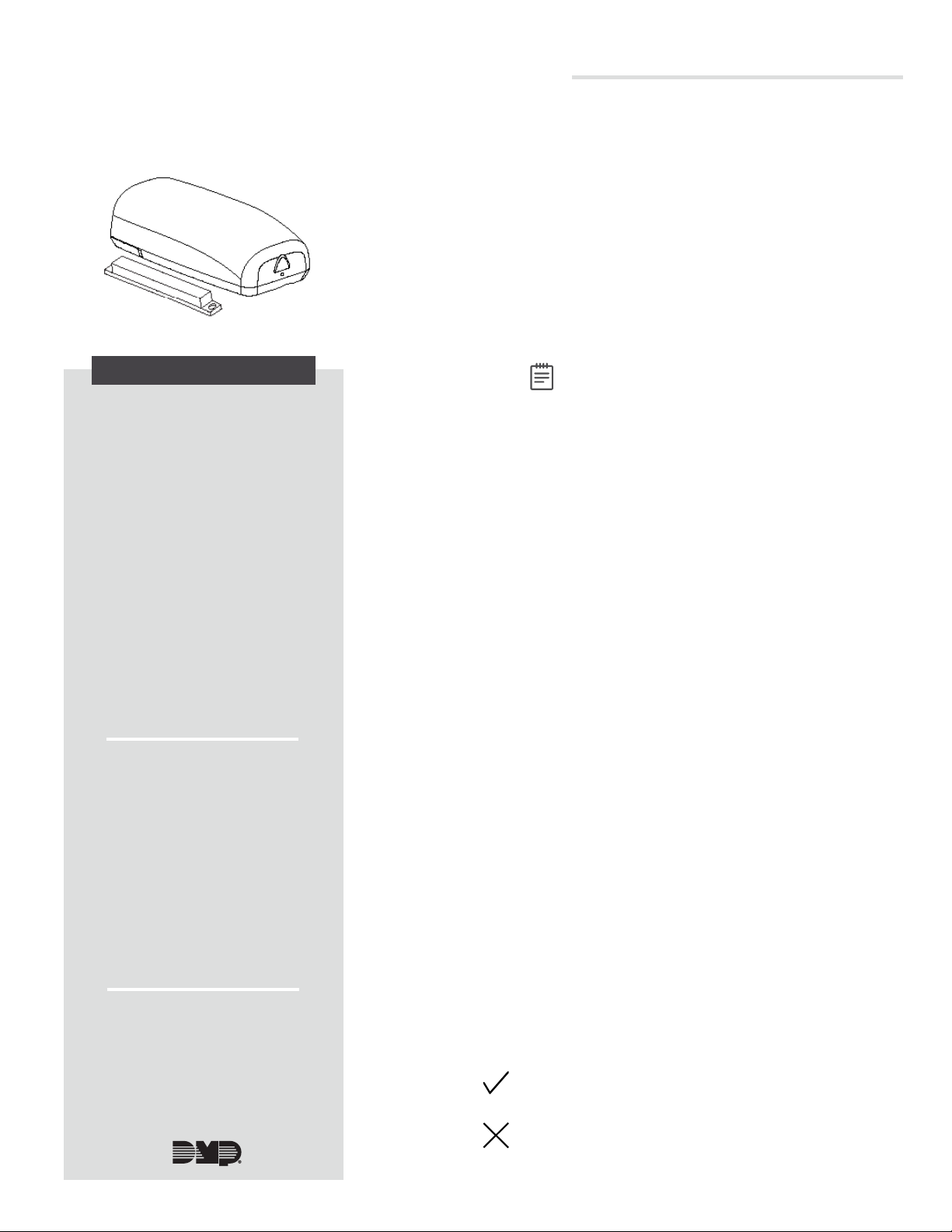
Figure 1: 1103INT Universal
Transmitter
Use a 3.0V lithium battery, a DMP Model CR123 battery, or
an equivalent model from Sony or Murata. When setting up
a wireless system, program zones and connect the wireless
receiver before installing the battery.
1. Push the button on the end of the 1103INT and
separate the two halves.
2. Observe polarity and place the battery in the holder
and press it into place.
3The 1103INT provides a survey LED that allows one person
to confirm communication with the wireless receiver or
panel while the cover is removed.
1. Hold the 1103INT in the exact desired location.
2. Press the tamper switch to send data to the panel
and determine if communication is confirmed or
faulty.
Confirmed: If communication is confirmed, for each
press or release of the tamper switch the LED blinks
immediately on and immediately off.
Faulty: If communication is faulty, the LED remains on
for about 8 seconds or flashes multiple times in quick
succession. Relocate the 1103INT or wireless receiver
until the LED confirms clear communication.
SELECT A LOCATION
DESCRIPTION
INSTALL THE BATTERY
2 1103INT INSTALLATION GUIDE | DIGITAL MONITORING PRODUCTS
MOUNT THE 1103INT
4Caution: Do not mount on ferromagnetic surfaces.
Mount the Transmitter
1. Remove the battery.
2. Hold the transmitter in place with the magnetic reed
switch closest to where the magnet will be mounted. See
Figure 2. Ensure the transmitter and the magnet are no
more than 1" (2.54 cm) apart.
3. Place the supplied #4 screw into the mounting hole and
secure the transmitter to the surface.
4. Replace the battery.
5. Snap the transmitter cover back onto the base.
Mount the Magnet
1. Place and hold the magnet directly on the door closest
to the magnetic reed switch, no more than 1" (2.54cm)
apart from the transmitter. See Figure3.
2. Use the provided #4screws to mount the magnet.
PLACEMENT OPTIONS
Figure 3: Placement Options
Figure 2: Transmitter Components
Survey LED
Mounting Hole
Magnetic Reed
Switches
Wiring and Connecting Contacts
When connecting an external contact to the terminal block in burglary applications, DMP recommends using
18 or 22 AWG unshielded wire. Do not use twisted pair or shielded wire. Locate a contact within 100ft
(30.5meters) of the 1103INT. Connect the contact as normally open (N/O) or normally closed (N/C) with the
470K end-of-line resistor. See Figure 4.
Note: The Normally Open YES NO option in the panel wireless zone programming has no effect on the
transmitter operation when using the 470K end-of-line resistor.
Figure 4: Contact Terminal Block Wiring
Mounting Hole
EXTERNAL CONTACTS
External Contact
Terminal Block
1103
Door
Window
External
Contact
Magnet
Program an internal
contact as the next
consecutive zone.
Program an
external contact as
the first zone.
Reed Switch Distances
Break (Alarm)
X: 18.5 mm
Y: 41.5 mm
Z: 35.5 mm
Make (Restore)
X: 14.5 mm
Y: 39.0 mm
Z: 19.5 mm
1103INT INSTALLATION GUIDE | DIGITAL MONITORING PRODUCTS 3
5
ADDITIONAL INFORMATION
TEST THE 1103INT
After installing the 1103INT, perform a Walk Test to confirm the 1103INT is communicating with the panel. At
the keypad for XT Series panels, enter 8144 (WALK). At the keypad for XR Series panels, enter 814 (WAL).
Select WLS. If the 1103INT fails to check in at the keypad, relocate the wireless device, receiver, or panel.
Using XT30INT/XT50INT/XTLplusINT/XTLtouchINT Series Panels
The 1103INT is designed for the XR150INT/XR550INT Series panels. However, it can be used with the
XT30INT/XT50INT/XTLplusINT/XTLtouchINT Series panels.
When used with XT panels, the tamper indication is sent through the internal contact zone only. When using the
external contact, the internal contact must also be programmed in a separate zone to provide tamper indication. The
supplied magnet must be mounted next to the 1103INT internal contact to restore the zone and allow the tamper
switch to have priority.
Replace the Battery and Sensor Reset to Clear LOBAT
1. Open the transmitter housing to expose the inside of the 1103INT.
2. Remove the old battery, observe polarity, and place the new battery in the holder.
3. Snap the cover back on the 1103INT.
Once the battery is replaced, a sensor reset is required at the keypad to clear the LOBAT message. On an LCD Keypad,
press and hold 2for two seconds. On a Graphic Touchscreen Keypad, press RESET. Enter your user code, if required.
The keypad displays SENSORS OFF followed by SENSORS ON.
COMPLIANCE SPECIFICATIONS
Designed, engineered, and
manufactured in Springfield, MO
using U.S. and global components.
LT-0702INT 20045 1.01
INTRUSION • FIRE • ACCESS • NETWORKS
2500 North Partnership Boulevard
Springfield, Missouri 65803-8877
417.831.9362 | DMP.com
International Certificates
Intertek (ETL)
EN 50130-4:2011 EMC - Product Family Standard.
Immunity Requirements for Components
of Fire, Intruder, and Social Alarm
Systems
EN 50130-5:2011 Alarm Systems. Environmental Test
Methods
EN 50131-1:2006+A1;A2 Alarm Systems. Intrusion and Hold-up
Systems. System Requirements
EN 50131-3:2009 Alarm Systems. Intrusion and Hold-up
Systems. Control and Indicating
Equipment
EN 50131-2-6:2008 Alarm Systems. Intrusion and Hold-up
Systems. Intrusion Detectors.
Requirements for Opening Contacts
(Magnetic)
EN 50131-5-3:2017 Alarm Systems. Intrusion systems.
Requirements for Interconnections
Equipment using Radio Frequency
Techniques
EN 61000-3-2:2009+A1;A2 Limits - Limits for Harmonic Current
Emissions (Equipment Input Current less
than or equal to 16A per Phase)
EN 61000-3-3:2013 Limits - Limitation of Voltage Changes,
Voltage Fluctuations and Flicker in
Public Low-Voltage Supply Systems, for
Equipment With Rated Current less than
or equal to 16A per Phase and Not
Subject to Conditional Connection
EN 61000-6-4:2018 Generic Standard - Emission Standard
for Industrial Environments
1103INT UNIVERSAL
TRANSMITTER
Specifications
Security Grade 2
Environmental Class II
Operating Temperature 0°C - 49°C
32°F - 120°F
Relative Humidity 80%
Weight .091kg
Battery
Life Expectancy 5 years (normal operation)
Type 3.0 V lithium CR123A
Low Battery 2.4 VDC or less
Frequency Range 863-869 MHz
Housing Material Flame retardant ABS
Dimensions 3.3”L x 1.6”W x 1.2”H
8.4 L x 4.06 W x 3.05 H cm
Color White
Accessories
CR123 3.0V Lithium Battery
Patents
U. S. Patent No. 7,239,236

Other DMP Electronics Transmitter manuals

DMP Electronics 1144 Series User manual

DMP Electronics

DMP Electronics 1144 Series User manual

DMP Electronics 1144INT Series User manual

DMP Electronics

DMP Electronics 1144INT Series User manual

DMP Electronics 1103 Series User manual

DMP Electronics

DMP Electronics 1103 Series User manual

DMP Electronics 1139 User manual

DMP Electronics

DMP Electronics 1139 User manual

DMP Electronics 1139 User manual

DMP Electronics

DMP Electronics 1139 User manual

DMP Electronics 1106-WINT User manual

DMP Electronics

DMP Electronics 1106-WINT User manual

DMP Electronics 1100 Series User manual

DMP Electronics

DMP Electronics 1100 Series User manual

DMP Electronics 1101-WINT User manual

DMP Electronics

DMP Electronics 1101-WINT User manual

DMP Electronics 1103 Series User manual

DMP Electronics

DMP Electronics 1103 Series User manual

DMP Electronics 1103INT User manual

DMP Electronics

DMP Electronics 1103INT User manual

DMP Electronics 1142INT User manual

DMP Electronics

DMP Electronics 1142INT User manual

DMP Electronics 1101 User manual

DMP Electronics

DMP Electronics 1101 User manual

DMP Electronics 1142 Series User manual

DMP Electronics

DMP Electronics 1142 Series User manual

DMP Electronics 1102 User manual

DMP Electronics

DMP Electronics 1102 User manual

DMP Electronics 1101 User manual

DMP Electronics

DMP Electronics 1101 User manual

DMP Electronics 1100 Series Installation guide

DMP Electronics

DMP Electronics 1100 Series Installation guide

DMP Electronics 1101 Series User manual

DMP Electronics

DMP Electronics 1101 Series User manual

DMP Electronics 1107 User manual

DMP Electronics

DMP Electronics 1107 User manual

DMP Electronics 1103 Series User manual

DMP Electronics

DMP Electronics 1103 Series User manual

DMP Electronics 1101 Series User manual

DMP Electronics

DMP Electronics 1101 Series User manual

DMP Electronics 1102 User manual

DMP Electronics

DMP Electronics 1102 User manual

DMP Electronics 1106 User manual

DMP Electronics

DMP Electronics 1106 User manual

DMP Electronics 1141 User manual

DMP Electronics

DMP Electronics 1141 User manual

DMP Electronics 1100INT Series User manual

DMP Electronics

DMP Electronics 1100INT Series User manual

Popular Transmitter manuals by other brands

Siemens Sitrans LR200 Compact operating instructions

Siemens

Siemens Sitrans LR200 Compact operating instructions

Spektrum DX20 instruction manual

Spektrum

Spektrum DX20 instruction manual

Danfoss AKS 41 instructions

Danfoss

Danfoss AKS 41 instructions

Becker Centronic SunWindControl SWC245A-II Assembly and operating instructions

Becker

Becker Centronic SunWindControl SWC245A-II Assembly and operating instructions

Fox Micron TXR Plus operating instructions

Fox

Fox Micron TXR Plus operating instructions

Kramer WP-110xl user manual

Kramer

Kramer WP-110xl user manual

GAPOSA Emitto Smart 16 QCTZ16Y Installer manual

GAPOSA

GAPOSA Emitto Smart 16 QCTZ16Y Installer manual

Nice HSTX8 Operation instructions

Nice

Nice HSTX8 Operation instructions

Vega VEGABAR 81 operating instructions

Vega

Vega VEGABAR 81 operating instructions

DAS MobileSpec MBS13200 manual

DAS

DAS MobileSpec MBS13200 manual

Dwyer Instruments GSTA Series Installation and operating instructions

Dwyer Instruments

Dwyer Instruments GSTA Series Installation and operating instructions

Jamara CX 2,4 GHz instructions

Jamara

Jamara CX 2,4 GHz instructions

Greyline DLT 2.0 user guide

Greyline

Greyline DLT 2.0 user guide

KLHA KM21X30-FIRE user manual

KLHA

KLHA KM21X30-FIRE user manual

Triton Blue WDMX-TR512 user manual

Triton Blue

Triton Blue WDMX-TR512 user manual

GESTRA NRGT 26-2n Original Installation & Operating Manual

GESTRA

GESTRA NRGT 26-2n Original Installation & Operating Manual

Beyerdynamic Synexis TS8 operating instructions

Beyerdynamic

Beyerdynamic Synexis TS8 operating instructions

Labom CK5 Series operating instructions

Labom

Labom CK5 Series operating instructions

manuals.online logo
manuals.online logoBrands
  • About & Mission
  • Contact us
  • Privacy Policy
  • Terms and Conditions

Copyright 2025 Manuals.Online. All Rights Reserved.