Greyline DLT 2.0 User manual

www.greyline.com
USER'S GUIDE
Installation & Operation
Instructions
Differential Level Transmitter
Model DLT 2.0
Manual Series A.1.3

Note: This page has been left blank intentionally.

Page 3
DLT 2.0 Differential Level Transmitter
INDEX
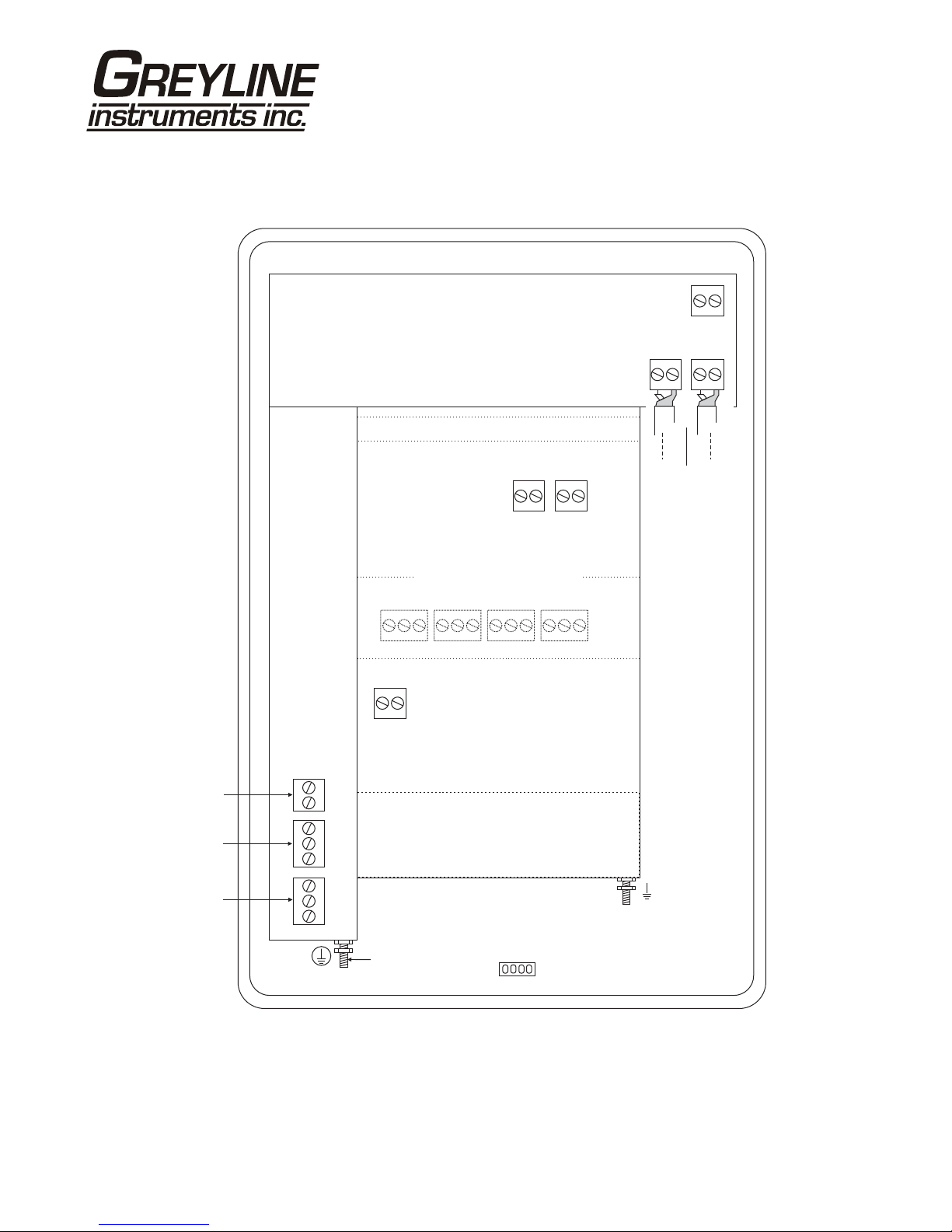
CONNECTIONS: ...............................................................................................4
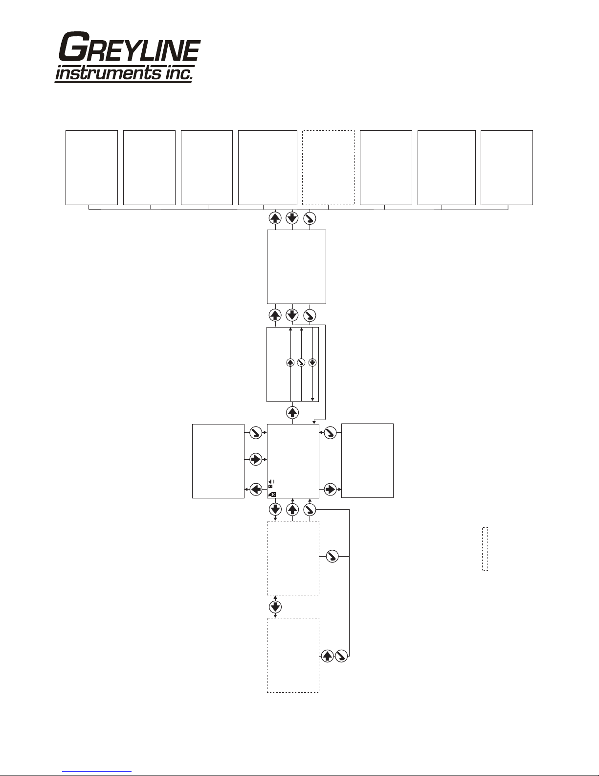
KEYPAD SYSTEM............................................................................................6
CALIBRATION MENU.....................................................................................7
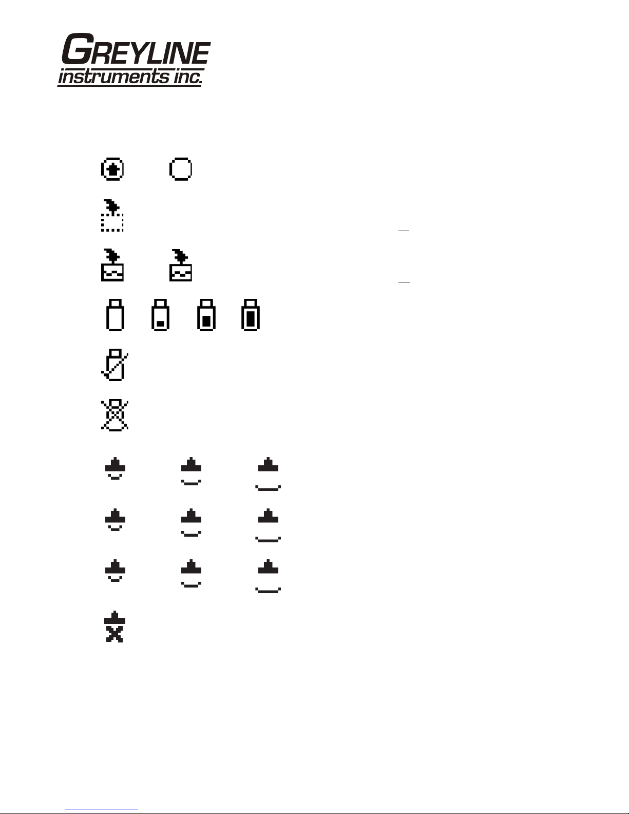
ICONS.................................................................................................................8
MAIN DISPLAY................................................................................................9
MESSAGE ICON...............................................................................................9
STATUS .............................................................................................................9
PASSWORD.....................................................................................................10
UNITS/MODE..................................................................................................11
CALIBRATION................................................................................................12
CHANNEL SETUP ..........................................................................................16
RELAY PARAMETERS..................................................................................17
SPECIAL FUNCTIONS...................................................................................18
SENSOR MOUNTING/LOCATION...............................................................20
APPLICATIONS HOTLINE............................................................................26
PRODUCT RETURN PROCEDURE..............................................................27
APPENDIX A - OPTIONS...............................................................................29
DATA LOGGING (Optional)...........................................................................35
CONVERSION GUIDE ...................................................................................37
SPECIFICATIONS...........................................................................................38
IMPORTANT NOTE: This instrument is manufactured and calibrated to meet product specifications.
Please read this manual carefully before installation and operation. Any unauthorized repairs or
modifications may result in a suspension of the warranty.
Available in Adobe Acrobat pdf format

Page 4
DLT 2.0 Differential Level Transmitter
CONNECTIONS:
POWER INPUT: 100 to 240 VAC 50/60Hz . No adjustments are necessary for voltages within this
range.
Optional DC: 9-32 VDC, 9 Watts. Connect to + and - terminals.
Optional Thermostat and Heater modules are available rated for 115 VAC or 230 VAC.
IMPORTANT NOTE: To comply with CSA/UL electrical safety standards, AC power input and relay
connection wires must have conduit entry to the instrument enclosure. Installation requires a switch,
overcurrent fuse or circuit breaker in the building (in close proximity to the equipment) that is marked
as the disconnect switch.
Risk of electric shock. Loosen cover screw to access connections. Only qualified personnel
should access connections.
Note: Use of instrumentation over 40°C ambient requires special field wiring.
Note: User replaceable fuse 2 Amp 250V (T2AL250V).
!

Page 5
DLT 2.0 Differential Level Transmitter
CONNECTIONS
HEATER OPTION
POWER
INPUT
AC
LN
Sens
B
Sens
A
4-20
B
Sens
4-20
A
Sens
NO
C
NC
NO
C
NC
–
+
4-20
Diff
RLY2
RLY1
AC
GND
NC
C
NO
NC
C
NO
NC
C
NO
NC
C
NO
RLY3 RLY4 RLY5 RLY6
EXTRA RELAYS OPTION
+ - + -
GND
USB HARNESS
CONNECTOR
DATA LOGGER OPTION
CORE
WHT
SHLD
GRN
CORE
WHT
SHLD
GRN

Page 6
DLT 2.0 Differential Level Transmitter
KEYPAD SYSTEM
The DLT 2.0 uses a menu system. Arrows show the four directions to leave a menu box. Press a key to
move to the next item in the direction shown. Move the cursor (underline) under numerals and increase
or decrease numerals with the and keys.
To store calibration values permanently (even through power interruptions), press .

Page 7
DLT 2.0 Differential Level Transmitter
CALIBRATION MENU
--Password----------
Password 0000
--Units/Mode--------
Mode}Flow
Linear ft
Volume USG
Time min
Temperature C
Display Alt
--Calibration-------
}Sensor B
Min Range 1.000ft
Max Range 12.000ft
Slope Offst 0.000ft
Damping 10%
LOE Time 30sec
USG/min
Tot 20130.8 USG
Relays 1 2 3 4 5 6
0.000
--Message-----------
Data log Logging
Log Used 0%
Sensor A Good
Sensor B Good
Temperature A 22C
Temperature B 22C
--Status------------
.00ft}Level A 12
Level B 11.30ft
Difference 0.70ft
20130.8USGTot
EC 100%A
EC B 100%
Relays 1 2 3 4 5 6
--Special Functions-
Language English
}
Analog Out 4-20mA
Backlight High
Reset Totalizer NO
Restore Defaults NO
New Password 0000
--Simulation--------
}Test Actual
ALevel 12.000ft
Flow B 0.00USG/m
Difference 0.00ft
Level A4-20mA 19.99
4-20mA Flow B 4.00
4-20mA Diff 20.00
Relays 1 2 3 4 5 6
--Relay Parameters--
Relay 1}
Sensor B
FlowFunction
Mode Pump
10000 USG/mOn
8000 USG/mOff
LOE mode Off
OAlternate N
--Data Logging-------
Log Site ID 0}
Mode Flow
Set Date Sep 22/2009
Set Time 14:24:40
Interval 30sec
Log Logging
--Configuration-----
}
Utility 1.25.05
Sonar 1.14
24Logger 1. T
6Relays
Analog 3Out
-- ----Channel Setup--
Type V-notch}
Size 22.5°
--Menu Selections----
Units / Mode}
Calibration
SetupChannel
Relay Parameters
Data Logging
Special Functions
Simulation
Configuration
OPTIONAL FEATURES
--24 hr log-------- -B
Date Feb. 12/20}10
50138 USGTotal
34.82 USG/mAverage
52.20 USG/mMaximum
11:08:00Max Time
0.000 USG/mMinimum
9:15:00Min Time
--24 hr log-------- -A
Date Feb. 12/20}10
4.82 ftAverage
8.20 ftMaximum
11:08:00Max Time
0.000 ftMinimum
9:15:00Min Time

Page 8
DLT 2.0 Differential Level Transmitter
ICONS
1. 2. Message waiting. Press .Ç
Data logging .off
1. 2. Data logging .on
1. 2. 3. 4. USB file download.
File download completed.
Download Error.
A sensor reading displayed. Echo OK.
B sensor reading displayed. Echo OK.
Difference reading displayed. Echo OK.
No Echo .
1.
A
1.
B
1.
D
2.
A
2.
B
2.
D
3.
A
3.
B
3.
D

Page 9
DLT 2.0 Differential Level Transmitter
MAIN DISPLAY
NOTE
Sensor A reads Range, Level or Volume
Sensor B reads Range, Level, Volume HRT and Flow
The display is configured from “Units/Mode” menu to display the Sensor
A measurement, Sensor B measurement or Level Difference. The DLT 2.0 will
start-up with this display.
The display also shows Units Selected, Totalizer and Relay States.
MESSAGE ICON
Press from the MAIN display to view status of the data logger and
error/warning messages provided by the instrument. The Message Icon will
appear on the MAIN display if error messages are being generated by the
instrument. Press to return to the main display.
STATUS
Press from the MAIN display to view instrument status. Level for both
sensors is displayed.
Tot Displays the current totalizer reading.
EC Displays echo confidence.
Relays Energized relays will display as a white character on a black
background.
24 HR LOG (Data Logging option only)
Press from the MAIN display to view a formatted flow report from instruments
with a built-in data logger. Press to scroll down one day or repeatedly to scroll
to a specific date. Press to toggle between Sensor A and Sensor B formatted
reports. Up to 365 days can be stored. Newest date will overwrite the oldest. Press
to return to the main display.
USG/min
Tot 20130.8 USG
Relays 1 2 3 4 5 6
0.000
--Message-----------
Data log Stopped
Log Used 0%
Sensor A Good
Sensor B Good
Temperature A 21C
Temperature B 21C
--Status------------
.00ft}Level A 12
Level B 11.30ft
Difference 0.70ft
20130.8USGTot
EC 100%A
EC B 100%
Relays 1 2 3 4 5 6
--24 hr log-------- -B
Date Feb. 12/20}10
50138 USGTotal
34.82 USG/mAverage
52.20 USG/mMaximum
11:08:00Max Time
0.000 USG/mMinimum
9:15:00Min Time

Page 10
DLT 2.0 Differential Level Transmitter
PASSWORD
The password (a number from 0000 to 9999) prevents unauthorized access to
the Calibration menu.
From the MAIN display press to get to Password. Factory default
password is 0000 and if it has not been changed press to proceed to the
Menu Selections screen.
If a password is required, press to place the cursor under the first digit and or
to set the number, then to the second digit, etc. Press or to proceed to
the Menu Selections screen.
A new password can be stored by going to Special Functions/New
Password.
--Password----------
Password 0000

Page 11
DLT 2.0 Differential Level Transmitter
UNITS/MODE
From Mode press the and then the or to select Level, Range,
Flow, HRT or Volume.
Range displays distance from the sensors to the target or liquid surface like a
tape measure. Range mode is useful to measure the exact distance
from the sensors to the zero level during calibration.
Level used to measure tank levels and level difference in linear units, or
"Head" in an open channel for comparison with flow tables.
Volume displays inventory of the two tanks in engineering units.
HRT select Horizontal Round Tank mode to calculate and display volume
units in horizontal round tanks.
Flow calculates channel flow through a flume or weir (sensor B only).
Sensor A measures level.
Volume,HRT or Flow gives the additional choice of volumetric units:
ft3 - cubic feet
USG - US gallons
USMG - US million gallons (FLOW only)
IG - Imperial gallons
IMG - Imperial million gallons (FLOW only)
m3 - cubic meters
L - liters
bbl - U.S. oil barrel
Press to store the selection, then to the next menu item and to enter.
Linear press and then or to select units of measurement.
Press to store the selection.
Time press and then or to select day, hr, min or
sec.
Temperature press then to select C or F (Centigrade or
Fahrenheit)
Press or to return to the Menu Selections screen.
--Units/Mode--------
Mode Flow
Linear ft
Volume USG
Time min
Temperature C
Display B
}
--Units/Mode--------
Mode Flow
Linear}in
ft
m
mm
--Units/Mode--------
}Volume USG
ft3
bbl
L
m3
IMG
IG
USMG
--Units/Mode--------
Mode Flow
Linear in
Volume USG
Time min
Temperature}C
F

Page 12
DLT 2.0 Differential Level Transmitter
CALIBRATION
Press to Calibration and to enter. Use or to position
before each menu item and to enter. When settings are completed press to
store and return to the Calibration menu.
Note - Sensors A & B do not need to be installed at the same height.
Sensor Select either Sensor A or Sensor B for calibration.
Min Range distance from the sensor face to highest expected level.
Max Range distance from the sensor face to channel floor.
MaxVol (Used for double tank monitoring applications, Volume and
HRT mode only. Enter the maximum volume of the vertical or
horizontal tank.
Note - to measure differential level the two sensors need a common reference
assumed to be a level channel floor.
Slope Offst Appears when calibrating Sensor B. Enter a slope offset value
to compensate for a sloped channel floor. Offset will be a
positive value when Sensor B channel floor is lower than Sensor
A channel floor.
Damping Minimum damping allows fast response to level changes.
Increasing damping slows the DLT 2.0's response to level
changes and is ideal to smooth the display and outputs in
turbulent conditions. Damping value is shown in percent (0-
99%). Some experimentation may be required to select the
optimum damping value. A value of 1% is recommended for
most applications and for fast level changes (up to ½ inch/sec -
13 mm/sec).
--Calibration-------
Sensor B
Min Range 1.000ft
Max Range 12.000ft
Slope Offst 0.000ft
Damping 10%
LOE Time 30sec
}
SENSOR ‘A’SENSOR ‘B’
MIN
RANGEMIN
RANGE
MAX
RANGEMAX
RANGE
SLOPE
OFFSET
BARSCREEN

Page 13
DLT 2.0 Differential Level Transmitter
LOE Time - Appears when calibrating Sensor B. Press and or to
change the number of seconds without receiving an echo before
the DLT 2.0 displays ECHO LOSS, and Control relays change
state as calibrated under Relay Parameters.
Factory default is 30 seconds and is recommended for most applications,
Minimum is 1 second and maximum is 99 seconds.
Press from the Units/Mode display to return to Menu Selections.

Page 14
DLT 2.0 Differential Level Transmitter
CALIBRATION
- for Level/Inventory Applications
1. Before starting the calibration determine:
a) MAX RANGE = ________________
(Maximum range = distance from Sensor to Zero level)
b) MAX LEVEL = ________________
(Maximum level of product being measured)
c) MIN RANGE = ________________
(Distance from sensor to Max Level)
Minimum range = MAX RANGE - MAX LEVEL
(must be at least 8" / 203 mm depending on sensor model)
2. Check the maximum range with the sensor installed:
a) When liquid is at zero level press to view the Range reading in the
Status menu. Use this range measured by the DLT 2.0 as the Max
Range setting.
or
b) Carefully measure distance from sensor to zero level with a tape measure,
and use this measurement as the Max Range setting.
MINIMUM RANGE:
In the CALIBRATION menu:
- Press to get to Min Range
- Press to move the cursor under the digits
- Use or to set the minimum range
Note: Min Range must be at least 12" (30.5 cm) for PZ32T sensors, 16"
(40.6 cm) for PZ52T and PZ34 sensors and 8" for PZ15 sensors. For correct tank
volume calculation in Hrt mode Min Range must be the actual distance
from the end of the sensor to the top of the tank.
MAXIMUM RANGE:
Press to get to Max Range
Enter Max Range determined above.
MAX LEVEL
ZERO LEVEL
MAX
VOLUME
MAX RANGE
MIN RANGE
TANKINVENTORY
LEVEL MODE
SENSOR
100%
0%
MAX LEVEL
ZERO LEVEL
MIN RANGE
TANKINVENTORY
RANGE MODE
SENSOR
0%
100%
MAX RANGE
TANKINVENTORY
HORIZONTAL ROUND TANK(HRT)MODE
MAX RANGE
MAX
VOLUME
MIN RANGE

Page 15
DLT 2.0 Differential Level Transmitter
CALIBRATION
- for Open Channel Flow
1. Before starting the calibration determine:
a) MAX RANGE = ____________________
(Maximum range = distance from the Sensor to Zero flow point)
b) MAX LEVEL = ____________________
(Maximum level of flow through flume or weir)
c) MIN RANGE = __________________
(Distance from sensor to Max Level)
Minimum range = MAX RANGE - MAX LEVEL
(must be at least 8" / 20.3 cm depending on sensor model).
2. Check the maximum range with the sensor installed by:
a) When liquid is at zero level press to view the Range reading in the
Status menu. Use this range measured by the DLT 2.0 as the Max
Range setting.
or
b) Carefully measure distance from sensor to zero level with a tape measure,
and use this measurement as the Max Range setting.
NOTE: The DLT 2.0 will not detect targets beyond user entered Max Range.
PALMER BOWLUS
SENSOR
ZERO LEVEL
MAX
RANGE
MIN
RANGE
MAX LEVEL
V-NOTCH
SENSOR
ZERO LEVEL
MAX
RANGE
MAX LEVEL
MIN
RANGE

Page 16
DLT 2.0 Differential Level Transmitter
CHANNEL SETUP
--Channel Setup------
Type V-notch
Custom
Khafagi
Rect Weir w/EC
Rect Weir
Trapezoidal
Leopld-Lagco
Palmer Bowlus
Parshall
}
--Channel Setup------
Type V-notch
Size 22.5
120
90
60
45
30
}
°
°
°
°
°
°
--Channel Setup------
Type Custom
K0.0000
n 0.0000
}
--Channel Setup------
Type Khafagi
Height 0.000ft
}
--Channel Setup------
Type RECT Weir w/EC
Height 0.000ft
}
--Channel Setup----
Type RECT Weir
Height 0.000ft
}
--Channel Setup------
Type Trapezoidal
Size Extra large 60
Large 60
Small 60
12in 45 SRCRC
2in 45 WSC
8in 60
}
°
°
°
°
°
°
--Channel Setup------
Type Leopld-Lagco
Size 36in
30in
24in
18in
12in
10in
8in
6in
}
--Channel Setup------
Type Palmer Bowlus
Size 48in
42in
36in
30in
27in
24in
21in
18in
15in
12in
10in
8in
6in
4in
}
--Channel Setup------
Type Parshall
Size 12ft
10ft
8ft
6ft
5ft
4ft
3ft
2ft
18in
12in
9in
6in
3in
2in
1in
}

Page 17
DLT 2.0 Differential Level Transmitter
RELAY PARAMETERS
Relay Press and or to select a relay (2 relays are standard, 4
additional are optional).
Sensor Press and or to select Sensor A, Sensor B or
Level Difference.
Function Press or to select Off, Temperature, Pulse
and Level.
Temperature Air temperature at the sensor location. Press and to set
the relay On and Off for specific temperatures.
Pulse Press and set digits to the flow volume increment required
between relay pulses. Use this feature for remote samplers,
chlorinators or totalizers. Minimum time between pulses is
2.25 seconds and pulse duration is 350 milliseconds.
Level Appears in Level, Range, Volume or HRT
modes only. Press to R Function and to select
Pump, LoAlm (low alarm) or HiAlm (high alarm).
Press to return to Menu Selections.
LOE Set relay state for ‘echo loss’ event (On, Off or Hold)
Alternate Pumps can be set to alternate when in pump mode.
DATA LOGGING (OPTIONAL)
Refer to Options section of this manual.
--Relay Parameters--
Relay 1
Sensor Diff
Function Flow
Mode Pump
On 10000 USG/m
Off 8000 USG/m
LOE mode Off
}
--Relay Parameters--
Relay 1
Function Temperature
On 0.0C
Off 9.0C
}
--Relay Parameters--
Relay 1
Function Pulse
On 10.000ft
}
³
--Relay Parameters--
Relay 1
Function Level
Mode Pump
On 12.000ft
Off 3.000ft
LOE mode Off
Alternate NO
}

Page 18
DLT 2.0 Differential Level Transmitter
SPECIAL FUNCTIONS
Language Select English, French or Spanish
and press .
Analog Out Select 4-20mA or 0-5V mode for the analog
output.
Backlight Select High, Medium or Low for continuous
backlight.
Select Key Hi/Lo for high backlight (for 1
minute) after a keypress and then Lo backlight
until a key is pressed again.
Select Key High, Med or Low for backlight
after a keypress and then backlight off until a key is
pressed again.
Reset Totalizer Press and select Yes to erase and restart the
totalizer at zero.
Restore Defaults Select Yes and press to erase all user settings
and return the instrument to factory default settings
New Password Select any number from 0000 to 9999 and
press . Default setting of 0000 will allow direct
access to the calibration menus. Setting of any
password greater than 0000 will require the
password to be entered to access the calibration
menus.
Press to return to Menu Selections.
--Special Functions-
Language English
Analog Out 4-20mA
Backlight High
Reset Totalizer NO
Restore Defaults NO
New Password 0000
}
--Special Functions-
Language English
}Backlight High
Medium
Low
Key Hi/Lo
Key High
Key Med
Key Low
Off

Page 19
DLT 2.0 Differential Level Transmitter
SIMULATION
Exercises the 4-20mA (0-5V) outputs, digital display and control relays.
Test Select Maximum and press to simulate maximum Flow, Range or
Level and to output 20mA (5V) for each analog channel.
Select Minimum and press to simulate minimum Flow, Ranges or
Levels and to output 4mA (0V) for each analog channel.
To simulate measurements between minimum and maximum set
Test to Actual and then enter values for the A and B
measurement. The differential calculation, analog outputs and control
relays will respond to the simulated values.
--Simulation--------
Test Actual
Level A 116.74in
Level B 62.11in
Difference 54.63in
4-20mA Level A 18.15
4-20mA Level B 11.53
4-20mA Diff 10.62
Relays 1 2 3 4 5 6
}

Page 20
DLT 2.0 Differential Level Transmitter
SENSOR MOUNTING/LOCATION
- Tank Level/Inventory Applications
Each DLT 2.0 Level Transmitter includes two non-
contacting ultrasonic sensors. The sensors must be
installed in a position to obtain unobstructed echoes
from the liquid or material being measured.
Mount the sensor away from pipes, ladders, or
structural members which might cause continuous false
echoes.
BAD GOOD
90°
Table of contents