DMSI 10 User manual

www.dmsimfg.com
You can also nd the manual online at:
www.dmsimfg.com/StandAloneManual
10 / 100 / 1000
Ethernet Media Converter Series
10 / 100 / 1000 mbps
www.dmsimfg.com
You can also nd the manual online at:
www.dmsimfg.com/StandAloneManual

www.dmsimfg.com
You can also nd the manual online at:
www.dmsimfg.com/StandAloneManual
CONTENT
Overview
Introduction
Cables
Specications
Packing List
Safety Precaution
Hardware Description
Front Panel
Back Panel
LED Indicators
DIP Switch
Fiber Port
Cabling
Network Connection
Installation
Troubleshooting
1
1
2
3
3
4
4
5
6-8
9
10
11
12
13

www.dmsimfg.com
You can also nd the manual online at:
www.dmsimfg.com/StandAloneManual
OVERVIEW
INTRODUCTION
DMSI’s 10/100 and 10/100/1000 stand-alone ethernet media
convertersareanecientandadaptablesolutionintheeldofLAN
campus networking. It mediates between a 10, 100, or 1000Base-
TX segment, and a 1000Base-FX segment. Gigabit converters can
extend the conventional 10M or 100/1000M fast ethernet out to
20km-120kmviathefastethernetber-opticalline.Itisprimarily
designed for large, higher speed/bandwidth demanding work group.
Please notify your sales representative immediately if any of the
items are missing or damaged.
CABLES
DMSI recommends using high quality, low loss bend insensitive
berpatchcordswithmediaconvertersolutions.Bendinsensitive
berprovidesauserfriendlysolutionforFTTDapplications,andis
very forgiving if bent in tight spaces. Recommend LC duplex to LC
duplex part numbers are:
Multimode:
Forusewith62.5µmOM1: 3131002F2N9xxxM
Forusewith50µmOM2/3: 3131002G2A9xxxM
Single-mode:
For use with SM OS2: 3131002Y2Y9xxxM
Replace xxx with required length in meters (three digits).

www.dmsimfg.com
You can also nd the manual online at:
www.dmsimfg.com/StandAloneManual
OVERVIEW
SPECIFICATIONS
TechnicalSpecications
Standard Protocol
IEEE 802.1q standard
IEEE 802.1p QoS
IEEE802.1d Spanning Tree
IEEE802.3 1000 Base-T standard
IEEE802.3ab standard
Operation Mode Full/Half duplex mode
Connectors UTP RJ-45
Fiber SC/ST/FC/LC
Bandwidth RJ 45 Port 0°C~50°C (32°F ~ 122°F)
Optical Port 125Mbps
Emission / Safety FCCPart15,ClassA,RoHSandCEMark
Environmental
Parameters
Work Temperature 0°C~50°C (32°F ~ 122°F)
Storage Temperature -40°C~70°C (-40°F ~ 158°F)
Humidit 5%~90% non-condensing
Cable
UTP Cable Cat5e,6,6AUTPorSTPcable
Single-mode
8.3/125μm,8.7/125μm,9/125,μm,
10/125μm(themaxdistanceupto
20 -120km)
Multimode
50/125μm,62.5/125μm
(the max distance up to 2km or
5km)
Dimensions (mm) 95mm(L) x 71.5mm(W) x25.4mm(H)
Warranty 3 years
Mean Time Between
Failure 114,000 hours
TAA Compliant Yes

www.dmsimfg.com
You can also nd the manual online at:
www.dmsimfg.com/StandAloneManual
PACKING LIST
1 - 10/100/1000 Media Conveter
1 - SFP (Optional)
1-10/100/1000StandAloneMediaConverterManual
1 - Power Supply
SAFETY PRECAUTION
Attention! If DC voltage is supplied by an external circuit, please
use a protection device on the power supply input.
OVERVIEW
www.dmsimfg.com
You can also nd the manual online at:
www.dmsimfg.com/StandAloneManual
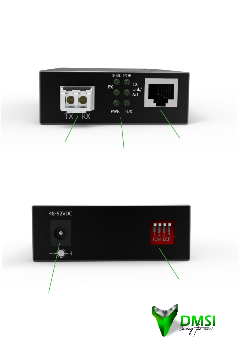
HARDWARE DESCRIPTION
FRONT PANEL
BACK PANEL
Power Supply Port
RJ-45 Port
LED Indicators
Duplex LC SFP
DIP Switch

www.dmsimfg.com
You can also nd the manual online at:
www.dmsimfg.com/StandAloneManual
HARDWARE DESCRIPTION
LED INDICATOR
LAMP STATUS EXPLANATION
FX On FX connection is good.
Blink FX data is transmitting.
Link/Act
On
Connection status display for electric link.
“ON”indicatesthatelectriclinkisincorrect
connection.
Blink Activestatusdisplayofberlink
“Blink”indicatespacketgoesthroughTxend.
FDX On Transceiver works in the full duplex mode.
O Transceiver works in the half duplex mode.
PWR On Power is on and normal.
100 On Lit when TP speed is 100Mbps.
1000 On FX speed is 1000Mbps.
O FX speed is 100Mbps.
LED Indicators
www.dmsimfg.com
You can also nd the manual online at:
www.dmsimfg.com/StandAloneManual
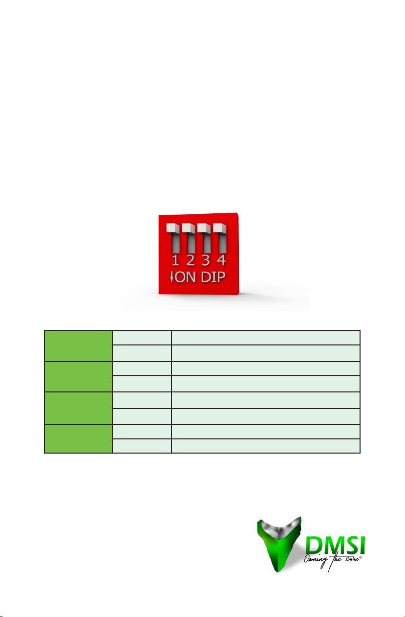
HARDWARE DESCRIPTION
DIP Switch
TheDIPswitchisusedtocongureoperationmodeforLLF(Link
Loss Forwarding) and operation mode for UTP/Fiber port. The
default value of DIP switch is OFF.
Stand-by Mode
SW1
ON Enable LFP
OFF Disable LFP
SW2
ON Cut-through(9K)
OFF Store-and-Forward
SW3
ON traccontrolon
OFF traccontrolo
SW4 ON FX speed is 100Mbps.
OFF FX speed is 1000Mbps.

www.dmsimfg.com
You can also nd the manual online at:
www.dmsimfg.com/StandAloneManual
HARDWARE DESCRIPTION
DIP Switch
LFP (link fault pass through) means the link fault on local side media
converter will be passed to the media converter on the remote side.
For instance if the media converter on the local side has the TP link
loss, the media converter will disconnect the link of transmit on
ber.Ontheremoteside,themediaconverterwillknowthereis
the linkage error and also disconnect the TP link. The LFP function
can immediately alarm network administrators of a link problem.
The LFP function includes the LLCF(link loss carry forward) and LLR
(Link loss return) function.
When the TP line of the media converter loses the link, the media
converter’s ber will disconnect the link of transmit, so that the
other side media converter will know that there is a link error. When
themediaconverter’sberlinelosesthelink,theconverter’sTPwill
disconnect, and the media converter on the other side will know
that there is a link problem. LLR(Link loss return) means when
there is a device (Ethernet switch or router) connected to the media
converter and the ber line loses the link, the media converter’s
berwilldisconnectthetransmitlink.
www.dmsimfg.com
You can also nd the manual online at:
www.dmsimfg.com/StandAloneManual
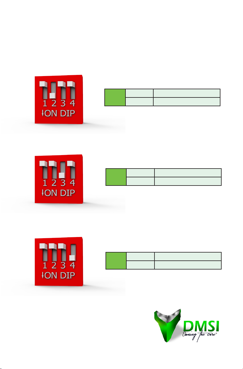
HARDWARE DESCRIPTION
DIP Switch
SW4 ON FX speed is 100Mbps.
OFF FX speed is 1000Mbps.
SW3 ON traccontrolon
OFF traccontrolo
SW2 ON Cut-through(9K)
OFF Store-and-Forward

www.dmsimfg.com
You can also nd the manual online at:
www.dmsimfg.com/StandAloneManual
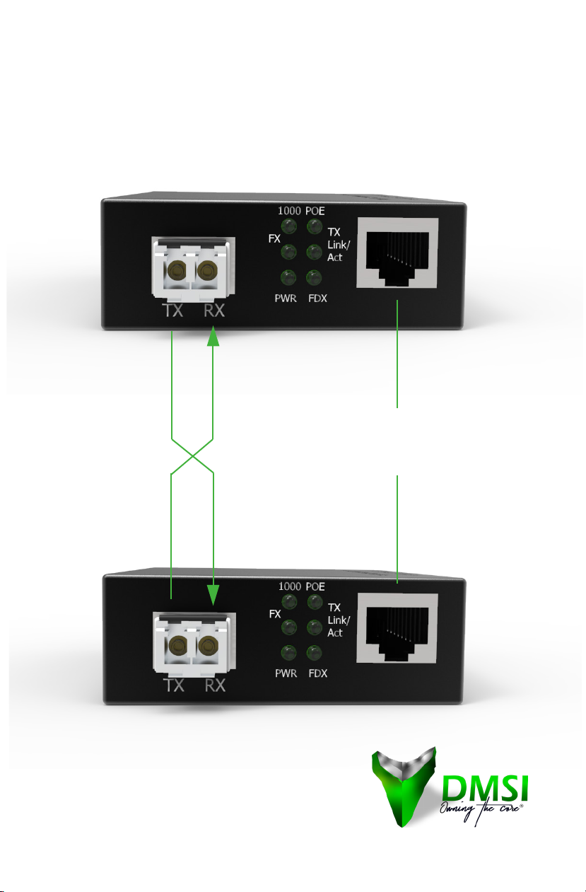
HARDWARE DESCRIPTION
Fiber Port
Whenyouconnecttheberporttoanotherone,pleasefollowthe
gurebelowto connectaccordingly.Wrongconnectionwillcause
the port to work incorrectly.
Cable Wiring (LC to LC)
TxA ---------------------------- ARx
Tx B ---------------------------- B Rx

www.dmsimfg.com
You can also nd the manual online at:
www.dmsimfg.com/StandAloneManual
HARDWARE DESCRIPTION
Cabling
Twisted-pair segments can be connected with unshielded twisted
pair (UTP) or shielded twisted pair (STP) cable. The cable must
comply with the IEEE 802.3u 1000Base TX standard for Category
5. The cable between the converter and the link partner (converter,
switch, hub, workstation, etc.) must be less than 100 meters (328
ft.) long.
Fiber segment using multi-mode connector type must use 50 or
62.5/125μmmulti-modeber.Usercanconnecttwodevicesupto
550M distance.
www.dmsimfg.com
You can also nd the manual online at:
www.dmsimfg.com/StandAloneManual
NETWORK CONNECTION
10/100/1000 Mbps port
(RJ-45 Connector)
at switch or end station
UTP
UTP
LC to LC Multimode Fiber up to 550M

www.dmsimfg.com
You can also nd the manual online at:
www.dmsimfg.com/StandAloneManual
NETWORK CONNECTION
Installation
1. Turn on the power supply of the converter.
2. ConnectlocalRXtoremoteTXviaopticalberwhenlocalFPL
indicator lights up.
3. Connect local TX to remote RX when both local and remote
FRX, and FPL indicators light up.
4. Ifitsasingle-berconverter,connecttheopticalber.
5. Turn on the power supply of the connected Ethernet devices.
6. Installation is completed.

www.dmsimfg.com
You can also nd the manual online at:
www.dmsimfg.com/StandAloneManual
NETWORK CONNECTION
Troubleshooting
1. Verify that you are using the right power cord/adapter (48-
52VDC). Please don’t use a power adapter with DC output
higher than the power input range as above or it may damage
the device.
2. Select the proper UTP or STP cable to construct your network
basedonyourbandwidthandperformancerequirements.Also,
be sure that the length of any twisted-pair connection does not
exceed 100 meters (328 feet).
3. Diagnosing LED Indicators: the unit can be easily monitored
through panel indicators to assist in identifying problems.
Solutions to common problems you may encounter can be found
on page 8.
4. If the power indicator does not light up when the power cord is
plugged in, you may have a problem with power cord. Check for
loose power connections, power losses, or surges at the power
outlet. If you still cannot resolve the problem, contact your local
dealer for assistance at www.dmsimfg.com.
5. If the LED indicators are normal, the connected cables are
correct, and the packets still cannot transmit, check your
system’sEthernetdevices’congurationorstatus.

www.dmsimfg.com
You can also nd the manual online at:
www.dmsimfg.com/StandAloneManual
You can also nd the manual online at:
www.dmsimfg.com/StandAloneManual
Diversied Materials Specialist, Inc (DMSI)
105 Triple Diamond Blvd. Unit 101
Venice, FL 34275
Info@dmsimfg.com
941-244-0935
www.dmsimfg.com
This manual suits for next models
2
Table of contents
Other DMSI Media Converter manuals


