DMSI 100MBPS User manual
OVERVIEW
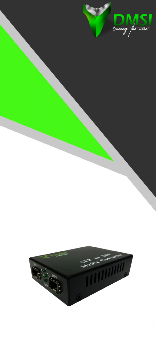
The Fiber to Fiber Media converter is an optical signal
device that can be adopted to convert optical digital
signals between single-mode / multimode ber, or
extend a multimode network. It is an ideal solution
to connect dierent ber types, distances, and
wavelengths across a variety of network architectures
for longer data transmission distances.
This device has 2 ber ports that can be used to
interconnect 2 ber connections. It is protocol
independent to address multiple applications.
This device can be connected to 2 100M ber modules,
or 1000M ber modules.
PACKING LIST
Fiber media converter 1pc
Power adapter 1 pc
User’s manual 1 pc
Note:
1. It is normal that the media converter heats up
when it’s working. To avoid overheating, please
keep the work environment dry, ventilated, and
cool.
2. Changes in the shell or outer box color won’t aect
the product’s function.
Diversied Materials Specialist, Inc (DMSI)
105 Triple Diamond Blvd. Unit 101 Venice, FL 34275
www.dmsimfg.com
FIBER TO FIBER
MEDIA
CONVERTER
SERIES
100MBPS | 1000MBPS
USER
MANUAL
www.dmsimfg.com
You can also nd the manual online at:
www.dmsimfg.com/berconvertermanual/

OVERVIEW
The Fiber to Fiber Media converter is an optical signal
device that can be adopted to convert optical digital
signals between single-mode / multimode ber, or
extend a multimode network. It is an ideal solution
to connect dierent ber types, distances, and
wavelengths across a variety of network architectures
for longer data transmission distances.
This device has 2 ber ports that can be used to
interconnect 2 ber connections. It is protocol
independent to address multiple applications.
This device can be connected to 2 100M ber modules,
or 1000M ber modules.
PACKING LIST
Fiber media converter 1pc
Power adapter 1 pc
User’s manual 1 pc
Note:
1. It is normal that the media converter heats up
when it’s working. To avoid overheating, please
keep the work environment dry, ventilated, and
cool.
2. Changes in the shell or outer box color won’t aect
the product’s function.
Diversied Materials Specialist, Inc (DMSI)
105 Triple Diamond Blvd. Unit 101 Venice, FL 34275
Info@dmsimfg.com | 941-244-0935
www.dmsimfg.com
FIBER TO FIBER
MEDIA
CONVERTER
SERIES
100MBPS | 1000MBPS
USER
MANUAL
www.dmsimfg.com
You can also nd the manual online at:
www.dmsimfg.com/berconvertermanual/

Max Rate 155M 155M 155M
Fiber Type Multimode Multimode /
Single-mode
Single-mode /
Single-mode
Wavelength 850nm 850nm /
1310nm 1310nm
Distance 2/2km 2/25km 25/25km
Min TX PWR -20.0dBm -20dBm /
-14dBm -14dBm
Max TX PWR -12dBm -12dBm
/-6dBm -6dBm
Sensitivity -30.0dBm -30.0dBm -31.0dBm
Link Budget 10.0dBm 10.0dBm /
16dBm 17.0dBm
Max Rate 1250M 1250M 1250M
Fiber Type Multimode Multimode /
Single-mode
Single-mode /
Single-mode
Wavelength 850nm 850/1310nm 1310nm
Distance 224m / 550m 0.55/20km 20/20km
Min TX PWR -12.0dBm -12dBm /
-9dBm -9dBm
Max TX PWR -4dBm -4dBm / 0dBm 0dBm
Sensitivity -18dBm -18dBm /
-23dBm -23dBm
Link Budget 6.0dBm 6dBm /
12.0dBm 12.0dBm
Power Lit when power is coming up.
FX1 Link
Lit when optical port 1 (FX1) connection
is good.
Blinks when FX data is transmitting.
FX2 Link
Lit when optical port 2 (FX2) connection
is good.
Blinks when FX data is transmitting.
FIBER PARAMETERS TECHNICAL SPECIFICATIONS
LED DESCRIPTION
This device has 3 LED indicators identifying the converter’s
work situation.
Fiber Ports SC | FC | ST | LC
Transfer Rate 155Mbps | 1250Mbps
Transfer Distance
100Mbps
series
Multimode: 2KM
Single-mode: 20~120KM
1000Mbps
series
Multimode: 220/550M
Single-mode: 10~100KM
Operation Mode
Duplex Type Full Duplex or Half
Duplex
Fiber
Multimode: 50/125μm
62.5/125μm
Single-mode:8/125μm
8.3/125μm 9/125μm
10/125μm
Power AC220V(100~265V), 50Hz; 5VDC
Environmental
Parameters
Work
Temperature
-10°C ~ 50°C
(14°F ~ 122°F)
Storage
Temperature
-20°C ~ 70°C
(-4°F ~ 158°F)
Humidity 5%~90% non-condensing
Dimensions 26mm(H) x 70mm(W) x 93mm(L)
Warranty Lifetime
Mean Time
Between Failure 114,000 hours
TAA Compliant Ye s
www.dmsimfg.com
INSTALLATION
1. Please install the ber media converter according to the
following steps:
2. Connect the ber patch cord or ber pigtail to the
relevant optical ber port respectively.
3. Note: Multimode ber must be connected to
multimode port in ber media converter and single-
mode ber to single-mode port; otherwise, the ber
can’t be connected through.
4. Connect power adapter’s DC plug to the DC socket
in the back of the ber media converter and connect
power adapter’s AC plug to the power AC socket, then
turn on the power. The “power” indicator will light up
once it’s on. The other two indicators signal the two
optical port’s condition. If the relevant optical ports are
connected to the device correctly, indicator light will be
on. All three indicators should have their lights on for
the device to work properly.

Max Rate 155M 155M 155M
Fiber Type Multimode Multimode /
Single-mode
Single-mode /
Single-mode
Wavelength 850nm 850nm /
1310nm 1310nm
Distance 2/2km 2/25km 25/25km
Min TX PWR -20.0dBm -20dBm /
-14dBm -14dBm
Max TX PWR -12dBm -12dBm
/-6dBm -6dBm
Sensitivity -30.0dBm -30.0dBm -31.0dBm
Link Budget 10.0dBm 10.0dBm /
16dBm 17.0dBm
Max Rate 1250M 1250M 1250M
Fiber Type Multimode Multimode /
Single-mode
Single-mode /
Single-mode
Wavelength 850nm 850/1310nm 1310nm
Distance 224m / 550m 0.55/20km 20/20km
Min TX PWR -12.0dBm -12dBm /
-9dBm -9dBm
Max TX PWR -4dBm -4dBm / 0dBm 0dBm
Sensitivity -18dBm -18dBm /
-23dBm -23dBm
Link Budget 6.0dBm 6dBm /
12.0dBm 12.0dBm
Power Lit when power is coming up.
FX1 Link
Lit when optical port 1 (FX1) connection
is good.
Blinks when FX data is transmitting.
FX2 Link
Lit when optical port 2 (FX2) connection
is good.
Blinks when FX data is transmitting.
FIBER PARAMETERS TECHNICAL SPECIFICATIONS
LED DESCRIPTION
This device has 3 LED indicators identifying the converter’s
work situation.
Fiber Ports SC | FC | ST | LC
Transfer Rate 155Mbps | 1250Mbps
Transfer Distance
100Mbps
series
Multimode: 2KM
Single-mode: 20~120KM
1000Mbps
series
Multimode: 220/550M
Single-mode: 10~100KM
Operation Mode
Duplex Type Full Duplex or Half
Duplex
Fiber
Multimode: 50/125μm
62.5/125μm
Single-mode:8/125μm
8.3/125μm 9/125μm
10/125μm
Power AC220V(100~265V), 50Hz; 5VDC
Environmental
Parameters
Work
Temperature
-10°C ~ 50°C
(14°F ~ 122°F)
Storage
Temperature
-20°C ~ 70°C
(-4°F ~ 158°F)
Humidity 5%~90% non-condensing
Dimensions 26mm(H) x 70mm(W) x 93mm(L)
Warranty Lifetime
Mean Time
Between Failure 114,000 hours
TAA Compliant Yes
www.dmsimfg.com
INSTALLATION
1. Please install the ber media converter according to the
following steps:
2. Connect the ber patch cord or ber pigtail to the
relevant optical ber port respectively.
3. Note: Multimode ber must be connected to
multimode port in ber media converter and single-
mode ber to single-mode port; otherwise, the ber
can’t be connected through.
4. Connect power adapter’s DC plug to the DC socket
in the back of the ber media converter and connect
power adapter’s AC plug to the power AC socket, then
turn on the power. The “power” indicator will light up
once it’s on. The other two indicators signal the two
optical port’s condition. If the relevant optical ports are
connected to the device correctly, indicator light will be
on. All three indicators should have their lights on for
the device to work properly.

OVERVIEW
The Fiber to Fiber Media converter is an optical signal
device that can be adopted to convert optical digital
signals between single-mode / multimode ber, or
extend a multimode network. It is an ideal solution
to connect dierent ber types, distances, and
wavelengths across a variety of network architectures
for longer data transmission distances.
This device has 2 ber ports that can be used to
interconnect 2 ber connections. It is protocol
independent to address multiple applications.
This device can be connected to 2 100M ber modules,
or 1000M ber modules.
PACKING LIST
Fiber media converter 1pc
Power adapter 1 pc
User’s manual 1 pc
Note:
1. It is normal that the media converter heats up
when it’s working. To avoid overheating, please
keep the work environment dry, ventilated, and
cool.
2. Changes in the shell or outer box color won’t aect
the product’s function.
Diversied Materials Specialist, Inc (DMSI)
105 Triple Diamond Blvd. Unit 101 Venice, FL 34275
www.dmsimfg.com
FIBER TO FIBER
MEDIA
CONVERTER
SERIES
100MBPS | 1000MBPS
USER
MANUAL
www.dmsimfg.com
You can also nd the manual online at:
www.dmsimfg.com/berconvertermanual/
Table of contents
Other DMSI Media Converter manuals


