BROADCAST CONSOLE Service & Support
500 Industrial Drive
New Bern, NC 28562 USA
+1 252 638 7000
www.wheatstone.com
by
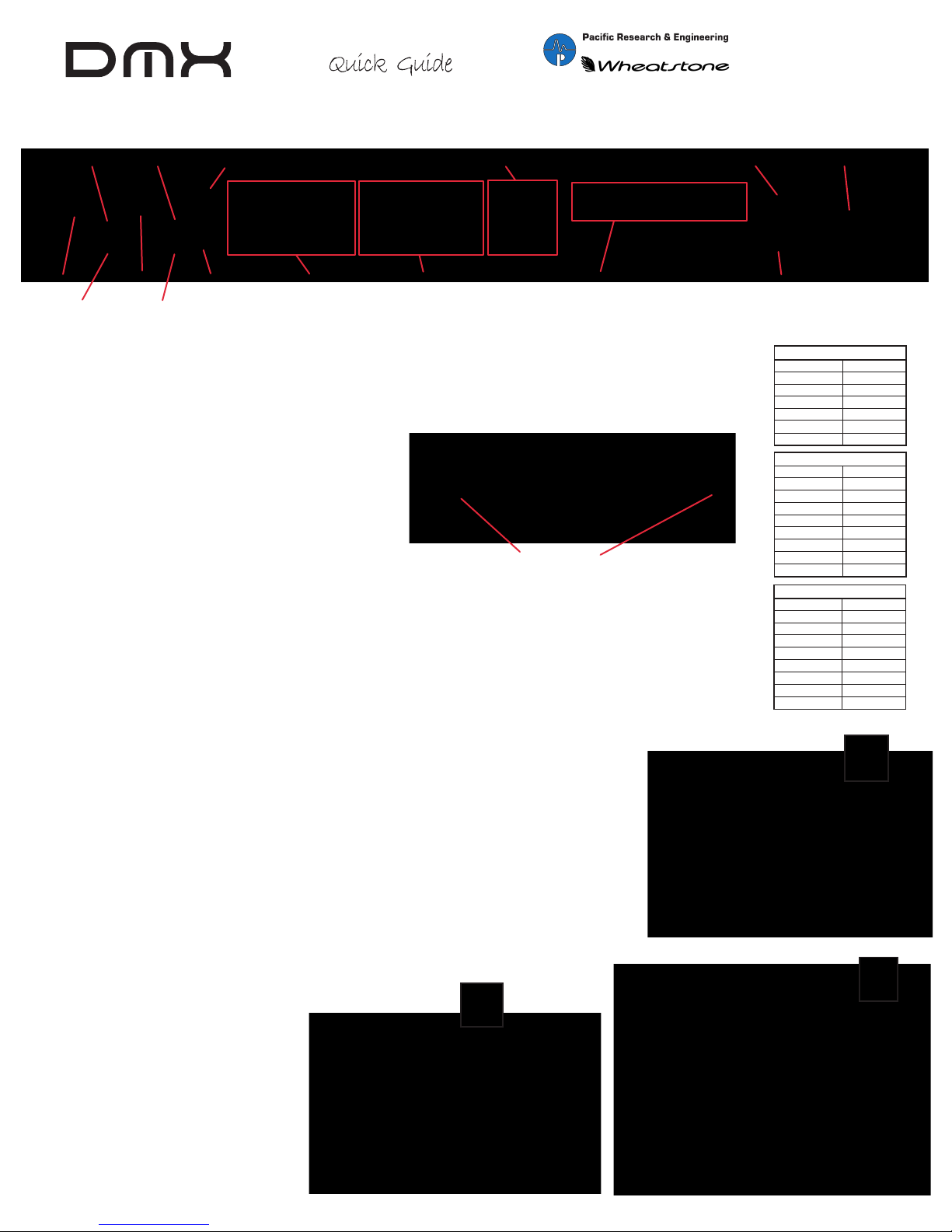
PR&E MIX ENGINE REAR PANEL CONNECTORS
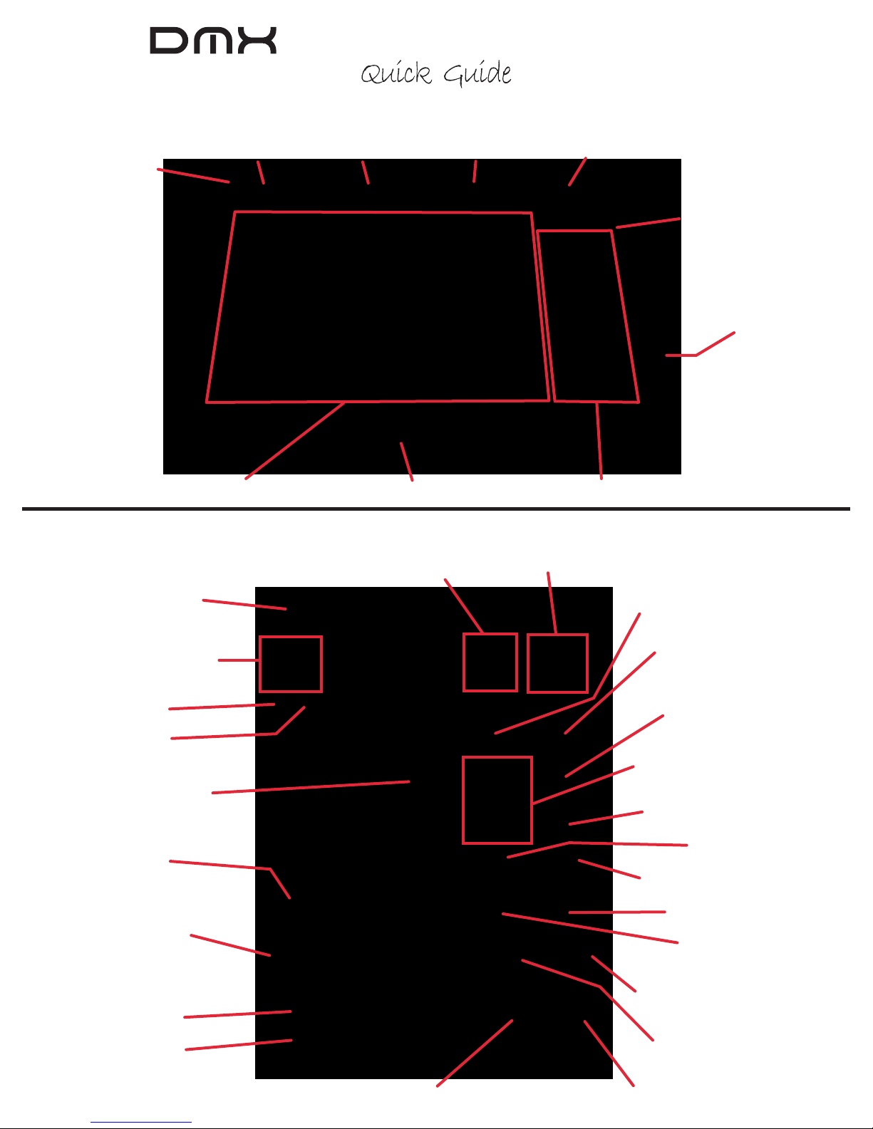
DMX SURFACE & MIX ENGINE CONNECTIONS
DMX SURFACE & MIX ENGINE CONFIGURATION
MIC 1 IN
PHANTOM
ON / OFF
MIC 1
PREAMP
GAIN
MIC 2
PREAMP
GAIN
LOGIC I/O (#)
(6 INS OR OUTS,
GND, +5 VDC)
POWER FOR THE
DMX-8 SURFACE
IEC AC INPUT
120 VOLT AC ONLY
EIGHT INPUTS (*)
(4 ANALOG,4 AES)
STEREO OR DUAL MONO
FIVE PORT GIGABIT SWITCH (%)
(CONNECT MIX ENGINE & SURFACE,PLUS SETUP PC,
VOXPRO PC, AUDIO SERVER,OR NETWORK SWITCH)
ETHERNET (%)
(JUMPER TO
SWITCH PORT)
PROGRAM BUS
OUTPUTS (*)
(4 ANALOG,4 AES)
MONITOR OUTPUTS (*)
FOR CR MONITORS (CR),BOARD OP HP AMP (HDPN),
STUDIO MONITORS (STU),AND CUE
MIC 2 IN
PHANTOM
ON / OFF
PREAMP
OUTPUTS (*)
(TYP. JUMPER TO
ANALOG INPUT 1)
CONNECTOR WIRING
STUDIOHUB+ WIRING
1 (WHT/ORG) Left + or AES +
2 (ORG) Left - or AES -
3 (WHT/GRN) Right +
6 (GRN) Right -
4 (BLU) GND
5,7,8 No Connection
RJ45 PIN (WIRE) SIGNAL
WNIP LOGIC WIRING
1 (WHT/ORG) GND
2 (ORG) Logic 1
3 (WHT/GRN) Logic 2
6 (GRN) Logic 5
4 (BLU) Logic 3
8 (BRN) +5 Volts
7 (WHT/BRN) Logic 6
5 (WHT/BLU) Logic 4
RJ45 PIN (WIRE) SIGNAL
ETHERNET WIRING
1 (WHT/GRN) TRANSMIT+
2 (GRN) TRANSMIT-
3 (WHT/ORG) RECEIVE+
6 (ORG) RECEIVE-
4 (BLU) N/C
8 (BRN) N/C
7 (WHT/BRN) N/C
5 (WHT/BLU) N/C
RJ45 PIN (WIRE) SIGNAL
#
%
*
Remove the upper rear cover from the Surface (three #1 Phillips screws) to access the DC power and Ethernet connec-
tors (see photo). After positioning the Surface on your countertop, mark and drill a small cable access hole for the DC
and Ethernet cables. On the DMX-8, the Mix Engine must be mounted so the supplied 16-foot DC cable can easily
connect to the Surface.The DMX-16 Surface has a separate DC supply so the Mix Engine can be located up to 100
meters from the DMX-16 Surface.
On a DMX-8 fasten the DC cable from the PWR OUT jack on the
Mix Engine to the power jack on the Surface. On a DMX-16,
connect the DC power supply cable to the Surface DC power
plug. On either Surface, connect a customer-supplied CAT6
cable from the Surface Ethernet jack to PORT 4 on the Mix
Engine’s Gigabit switch. Replace the rear cover panel on the
Surface.
On the Mix Engine, install a short Ethernet cable between the ETHERNET jack and PORT 5 on the Gigabit switch. Plug in
the supplied IEC AC cord to the Mix Engine and connect to an isolated ground AC outlet. It will take roughly two
minutes for the Mix Engine and Surface to complete their power up process.
The DMX ships with a USB thumb drive with three software apps (DMX Surface Setup, PR&E Navigator, PR&E System
Configuration Tool). These apps are used to configure and manage your DMX consoles.The thumb drive also has a PDF of
the user manual and this Quick Guide.The DMX apps can be installed on any Windows PC (XP, 7, 8, or 10; 32- or 64-bit
processor). For best performance the PC needs at least 1 GB of memory and a 1.8GHz or faster processor.
This“admin PC” needs to have one NIC assigned to an IP address of 192.168.87.20. Connect the NIC to
one of the Mix Engine’s Gigabit switch ports using a straight-thru CAT5 cable (customer-supplied).
The PR&E System Configuration Tool is used change the device settings on a DMX Surface, Mix Engine,
or Razor Interface. Since every DMX device ships with the same IP address: DMXSurface = 192.168.87.201;
Mix Engine = 192.168.87.101 (Blade ID=1); Analog Razor = 192.168.87.50; AES razor = 192.168.87.60; and
A/D Razor = 192.168.87.70.The Config Tool allows multiple consoles to be easily networked together by
automatically changing the default IP address and Mix Engine IDs to be uniquely set for each device in
your facility.
The DMX Surface Setup app “marries”the Mix Engine and Surface.It’s then used to configure the Surface
for a specific application by setting various Surface options including which sources appear on each
source selector and setting the various channel attributes that can be assigned to a source, along with
a host of other settings which are in five vertical page tabs.
The PR&E Navigator is used for DMX system
management. It is initially used to name
system signals. It is then used to connect
signals by clicking in an X-Y crosspoint grid;
to create and take salvos to allow many
system functions to be done simultaneously;
to manage the system through a built-in
syslogger; along with many other system
control functions.
Surface DC Power & Ethernet Connections
DMX Surface Setup Icon& VDips Page Tab PR&E Navigator Icon & Crosspoint Grid
PR&E System Configuration Tool & Icon
Rev B