Dodge SCXT 305E User manual

1
Single Reduction Screw Conveyor and
Hydroil Screw Conveyor Drive
Instruction Manual
SCXT / HSCXT 305E
SCXT / HSCXT 405E
SCXT / HSCXT 505E
SCXT / 605E
SCXT / 705E
These instructions must be read thoroughly before installation or operation. This instruction manual was accurate at the time of
printing. Please see dodgeindustrial.com for updated instruction manuals.
WARNING: To ensure the drive is not unexpectedly started, turn o and
lock-out or tag power source before proceeding. Failure to observe these
precautions could result in bodily injury.
WARNING: Because of the possible danger to person(s) or property
from accidents which may result from the improper use of products,
it is important that correct procedures be followed. Products must be
used in accordance with the engineering information specied in the
catalog. Proper installation, maintenance and operation procedures
must be observed. The instructions in the instruction manuals must
be followed. Inspections should be made as necessary to assure
safe operation under prevailing conditions. Proper guards and other
suitable safety devices or procedures as may be desirable or as may
be specied in safety codes should be provided, and are neither
provided by Dodge®nor are the responsibility of Dodge. This unit and
its associated equipment must be installed, adjusted and maintained
by qualied personnel who are familiar with the construction and
operation of all equipment in the system and the potential hazards
involved. When risk to persons or property may be involved, a holding
device must be an integral part of the driven equipment beyond the
speed reducer output shaft.
WARNING: All products over 25 kg (55 lbs) are noted on the shipping
package. Proper lifting practices are required for these products.
Figure 1 - SCXT Assembly
ASSEMBLY
NOTE: A screw conveyor drive consists of three
sub-assemblies listed below.
1. Reducer – Includes speed reducer, shaft retainer, retainer bolt
and lockwasher
2. Adapter Assembly – Includes adapter bolts, lockwashers, a
lip type seal and a seal retaining ring
3. Drive Shaft – Includes shaft and key
Make certain none of the parts have been damaged in shipment.
Any shipping damage should be promptly reported to the
carrier. Read all instructions in this manual before attempting to
assemble or install the screw conveyor drive. It is important that
assembly be performed in the following sequence and that each
step be completed before continuing to the next.
NOTE: This reducer is compatible with the Dodge sensor
that can be installed in the adapter plug labeled “smart
sensor”. The plug and sensor can be moved to dierent
locations as required by mounting position.
FIGURE 1: SCXT ASSEMBLY
DRIVESHAFT
SEAL
RETAINING
RING
LIP SEAL OR
BRAIDED SEALS
ADAPTER
SCREW CONVEYOR DRIVE
SPEED REDUCER
ADAPTER BOLT
AND LOCK WASHER
DRIVESHAFT
KEY
DRIVESHAFT
RETAINER
RETAINER BOLT
AND LOCKWASHER

2MN16042
Standard Lip Type Seal – Assembly
1. Place adapter on a work bench with the large trough end
facing up.
2. Place seal in adapter so that spring faces out. Seal should be
tapped evenly into place in the adapter with a small hammer,
applying force only on the outer corner of the seal. Fill cavity
between lips of seal with grease.
3. Install seal retainer ring by tapping with a hammer.
4. Move to "Adapter To Reducer – Assembly" section.
Optional Adjustable Packing Adapter – Assembly
1. Place adapter on a work bench with the large trough end
facing up.
2. Install the two threaded studs from the trough end, using a
at head screwdriver in the slotted end of the studs. Install the
studs just far enough to allow the packing retainer ange to
clear the top of the studs on the opposite side.
3. For some smaller sizes, it may be necessary to place the
adapter into place before running the studs down, and install
the packing kit from the trough side, and then the keeper
plate.
4. Install the retainer ring by tapping evenly with a hammer.
5. Flip over the adapter, placing the larger trough end down on
the work bench.
6. Compress and install one braided seal into the machined
bore of the adapter. Continue with the other two braided
seals, osetting the joints.
7. Install the packing retainer, placing the machined shoulder
against the braided seals.
8. Install the nuts hand tight. Do not tighten these nuts with a
tool until the driveshaft has been installed.
9. See Figure 2 for assembly view with nomenclature.
10. Move to "Adapter To Reducer – Assembly" section.
Adapter To Reducer – Assembly
1. Carefully place the reducer on its side in order to install the
adapter to the reducer.
2. Taking into consideration the nal orientation of the gearbox,
install the adapter with one opening in the downward position.
3. Align the small end of the adapter against the machined
surface of the reducer.
4. Install the four bolts with washers and tighten them to the
torque rating specied in Table 5.
5. Position the driveshaft with key, leading with the end that is
drilled and tapped for the retaining bolt.
6. Install the driveshaft though the adapter and into the gearbox,
aligning the key in the driveshaft keyway with the keyway in
the output hub of the reducer.
NOTE: Be extremely careful when sliding adapter section
of shaft through seal to prevent seal lips from being
damaged or rolled over.
7. Install the shaft retainer, lock washer and bolt, and tighten to
the torque rating specied in Table 5.
8. If using the optional adjustable packing adapter, hand-tighten
the nuts on the packing retainer then rotate one additional
turn with the appropriate tool. Once in operation, these nuts
can be retightened if the braided seals wear during normal
operation. Braided seals can be replaced as needed.
INSTALLATION
1. Use lifting bracket where applicable to lift reducer.
2. Determine the running positions of the reducer (see Figure 3).
Note that the reducer is supplied with six plugs; four around
the sides for horizontal installations and one on each face for
vertical installations. These plugs must be arranged relative
to the running positions as follows:
Horizontal Installations – Install the magnetic drain plug in
the hole closest to the bottom of the reducer. Install the lter/
ventilation plug in topmost hole. Of the two remaining plugs
on the sides of the reducer, the lowest one is the minimum oil
level plug.
Vertical Installations – Install the lter/ventilation plug in
the hole provided in the upper face of the reducer housing as
installed. If space is restricted on the upper face, install the
vent in the highest hole on the side of the reducer per Figure
3 using the optional vertical vent kit. Install a plug in the hole
in the bottom face of the reducer. Do not use this hole for
the magnetic drain plug. Install the magnetic drain plug in
the lowest hole on the sides of the reducer. Of the remaining
holes on the sides of the reducer, use the plug in the upper
housing half for the minimum oil level plug.
Figure 2 - Optional Adjustable Packing Adapter
POSITION A
POSITION B
D
L
B
P
D
L
B
P
HORIZONTAL APPLICATIONS
VERTICAL APPLICATIONS
P
B
L
D
D
L
B
P
D
L
B
P
D
L
B
P
POSITION C
POSITION D
POSITION E
POSITION F
B=BREATHER D=DRAIN L=LEVEL P=PLUG
FIGURE 3- MOUNTING POSITIONS
Figure 3 - Mounting Positions

3MN16042
Below 15 RPM output speed, oil level must be adjusted to
reach the highest oil level plug. If reducer position is to vary
from those shown in Figure 3, either more or less oil may be
required. Consult Dodge.
The running position of the reducer in a horizontal application
is not limited to the four positions shown in Figure 3. However,
if running position is over 20° in position B and D or over 5°
in position A and C—either way from sketches—the oil level
plug cannot be used safely to check the oil level, unless the
reducer is swung to within 20° for position A and C or within
5° for position B and D of the positions shown in Figure 3.
Because of the many possible positions of the reducer, it
may be necessary or desirable to make special adaptations
using the lubrication lling holes furnished along with other
standard pipe ttings, stand pipes and oil level gauges as
required.
NOTE: If motor mount, motor, and sheaves are to be
installed on reducer before mounting screw conveyor
drive to trough end, bypass step 3; perform steps 4 and 5,
and then return to step 2.
3. Use lifting tab to hoist screw conveyor drive into position.
Slide shaft into screw and adapter over trough end studs.
Only one set of adapter holes will t over the trough end
studs. If the mounted position of the screw conveyor drive
varies more than 15° from any of the four horizontal mounting
positions shown in Figure 3, an incorrect set of holes has
been selected for coupling adapter to reducer. This can
be corrected by removing adapter screws and rotating the
reducer to its proper position. Reinstall and tighten adapter
screws to torque specied in Table 5. Install lockwashers and
tighten nuts on trough end studs. Attach drive shaft to screw.
4. Motor Mount Installation
The motor mount must be installed on the reducer as shown
in Figure 4.
Remove the required housing bolts on the side of the
reducer. Place the motor mount brackets in position and
install the longer housing bolts supplied with the motor
mount assembly. Do not fully tighten the housing bolts at this
time.
Install the bottom plate to the motor mount brackets and
tighten with the hardware provided. Next, tighten the housing
bolts to the torque values listed in Table 5.
Install the four adjusting studs to the bottom plate using
the jam nuts provided and securely tighten. These nuts will
not require any further adjustment. Add one additional jam
nut to each stud and thread approximately to the middle of
the stud. Install the top motor plate on top of the jam nuts.
Assemble the remaining jam nuts on studs to secure top
motor plate. Do not fully tighten these nuts yet.
Mount motor, drive and driven sheaves, and V-belts.
NOTE: Mount driven sheave as close to the reducer
housing as practical.
Adjust V-belts to the proper tension by adjusting the jam nuts
and securely tighten.
Check all bolts to ensure that they are securely tightened.
5. Install sheave on input shaft as close to reducer as practical.
CAUTION: Unit is shipped without oil. Add proper amount
of recommended lubricant before operating. Failure to
observe this precaution could result in damage to or
destruction of the equipment.
6. Fill gear reducer with the recommended volume of lubricant
per Table 1.
LUBRICATION
IMPORTANT: Because Torque-Arm reducers are shipped
without oil, it is extremely important to add the proper
amount of lubricant prior to operating reducer. For most
applications a high-grade petroleum-base rust and oxidation
inhibited (R&O) gear oil is suitable. Under severe conditions
EP-type oils can be used. See Table 1 for proper oil volume
and viscosity requirement.
Follow instructions on reducer warning tags.
Lubrication is very important for satisfactory operation. The
proper oil level must be maintained at all times. Frequent
inspection, at least monthly, with the unit not running and
allowing sucient time for the oil to cool and the entrapped air
to settle out of the oil should be made by removing the level plug
and verifying the level is being maintained. If oil level is low, add
the proper lubricant until the oil volume is increased to the correct
level.
After an initial operation of about two weeks, the oil should be
changed. If desired, this oil may be ltered and reused. After
the initial break in period, under average industrial operating
conditions, the lubricant should be changed every 2,500 hours
of operation. At every oil change, drain reducer and ush with
kerosene, clean magnetic drain plug and rell to proper level with
new lubricant.
Under extreme operating conditions, such as rapid rise and fall
of temperature, dust, dirt, chemical particles, chemical fumes, or
oil sump temperatures above 200°F, the oil should be changed
every one to three months, depending on severity of conditions.
CAUTION: Too much oil will cause overheating and too little
will result in gear failure. Check oil level regularly. Failure to
observe this caution could result in bodily injury.
Heating is a natural characteristic of enclosed gearing. A
maximum gear case temperature approaching 200°F is
not uncommon for some units operating in normal ambient
temperatures of 80°F. When operating at the rated capacity with
proper lubrication, no damage will result from this temperature.
FIGURE 4: COMPLETE DRIVE
Figure 4 - Complete Drive

4MN16042
This maximum temperature was taken into consideration during the design of the reducer.
Table 1–Oil Volumes
Reducer
Approximate Volume of Oil to Fill Reducer to Oil Level Plug ① ④
② Position A ② Position B ② Position C ② Position D ② Position E ② Position F
Size ③ Qt ③ Qt ③ Qt ③ Qt ③ Qt ③ Qt
(H)SCXT305E 7/8 1-1/2 1-3/8 1-3/8 2-1/2 3-1/8
(H)SCXT405E 1-1/2 2-1/4 2-1/8 1-7/8 4 4-7/8
(H)SCXT505E 3-3/8 4-1/4 3-7/8 3-3/4 7-3/4 9
SCXT605E 4-1/2 5-3/4 4-1/2 5 12 11
SCXT705E 7-1/2 9 7-1/2 9-1/4 19 17-1/4
①Oil quantity is approximate. Service with lubricant until oil runs out of oil level hole.
② Refer to Figure 3 for mounting positions.
③ US measure: 1 quart = 32 uid ounces = .94646 liters.
④ Below 15 RPM output speed, oil level must be adjusted to reach the highest oil level plug. If reducer position is to vary from those shown in Figure
1, either more or less oil may be required. Consult Dodge.
Table 2–Oil Recommendations
ISO Grades For Ambient Temperatures of 50°F to 125°F (Refer to notes below)
Output RPM
(H)SCXT305E (H)SCXT405E (H)SCXT505E SCXT605E SCXT705E
301–400 220 220 220 220 220
201–300 220 220 220 220 220
151–200 220 220 220 220 220
126–150 320 220 220 220 220
101–125 320 320 220 220 220
81–100 320 320 320 220 220
41–80 320 320 320 220 220
11–40 320 320 320 320 320
1–10 320 320 320 320 320
ISO Grades For Ambient Temperatures of 15°F to 60°F (Refer to notes below)
Output RPM
(H)SCXT305E (H)SCXT405E (H)SCXT505E SCXT605E SCXT705E
301–400 150 150 150 150 150
201–300 150 150 150 150 150
151–200 150 150 150 150 150
126–150 220 150 150 150 150
101–125 220 220 150 150 150
81–100 220 220 220 150 150
41–80 220 220 220 150 150
11–40 220 220 220 220 220
1–10 220 220 220 220 220
Notes:
1. Assumes auiliary cooling where recommended in the catalog
2. Pour point of lubricant selected should be at least 10°F lower than expected minimum ambient starting temperature
3. Extreme pressure (EP) lubricants are not necessary for average operating conditions
4. Special lubricants may be required for food and drug industry applications where contact with the product being manufactured may occur.
Consult a lubrication manufacturer's representative for their recommendations.
5. For reducers operating in ambient temperatures between -22°F (-30°C) and 20°F (-6.6°C), use a synthetic hydrocarbon lubricant, ISO100
grade or AGMA 3 grade (for example, Mobil SHC627). Above 125°F (51°C), consult Dodge Application Engineering at +1 864 284 5700 for
lubrication recommendation.

5MN16042
OIL VISCOSITY EQUIVALENCY CHART
2000
1000
800
600
500
400
300
200
100
80
60
50
40
30
20
10
8
6
5
4
3
2
70
60
50
40
30
20
10
8
5
4
9
7
6
1500
1000
680
460
320
220
150
100
68
8A
8
7
6
5
4
3
2
85W
250
140
90
80W
46
32
22
15
10
7
5
1
75W
3
2
300
200
150
100
80
70
60
50
40
35
32
400
500
600
800
1000
1500
2000
3000
4000
5000
6000
8000
10,000
cSt/
40°C 100°C
cSt/ ISO
VG
AGMA
GRADES
GRADES
GEAR OILS
SUS/
100°F
SUS/
210°F
SAE
KINEMATIC
VISCOSITIES
SAYBOLT
VISCOSITIES
200
300
100
90
80
70
60
55
50
45
40
VISCOSITIES CAN BE
RELATED HORIZONTALLY
ONLY.
VISCOSITIESBASED ON
96 VI SINGLE GRADE
OILS.
ISO ARE SPECIFIED AT
40°C.
AGMA ARE SPECIFIED AT
40°C.
SAE 75W, 80W, AND 85W
SPECIFIED AT LOW
TEMPERATURE. EQUIVALENT
VISCOSITIES FOR 100°F
AND 200°F ARE SHOWN.
SAE 90 TO 250 SPECIFIED
AT 100°C.

6MN16042
GUIDELINES FOR (H)SCXT REDUCER
LONG-TERM STORAGE
During periods of long storage, or when waiting for delivery or
installation of other equipment, special care should be taken to
protect a gear reducer to have it ready to be in the best condition
when placed into service.
By taking special precautions, problems such as seal leakage
and reducer failure due to lack of lubrication, improper lubrication
quantity, or contamination can be avoided. The following
precautions will protect gear reducers during periods of extended
storage:
Preparation
1. Drain oil from the unit. Add a vapor phase corrosion inhibiting
oil (VCI-105 oil by Daubert Chemical Co.) in accordance with
Table 3.
2. Seal the unit airtight. Replace the vent plug with a standard
pipe plug and wire the vent to the unit.
3. Cover all unpainted exterior parts with a waxy rust
preventative compound that will keep oxygen away from the
bare metal (Non-Rust X-110 by Daubert Chemical Co. or
equivalent).
4. The instruction manuals and lubrication tags are paper and
must be kept dry. Either remove these documents and store
them inside, or cover the unit with a durable waterproof cover
which can keep moisture away.
5. Protect reducer from dust, moisture, and other contaminants
by storing the unit in a dry area.
6. In damp environments, the reducer should be packed inside
a moisture-proof container or an envelope of polyethylene
containing a desiccant material. If the reducer is to be stored
outdoors, cover the entire exterior with a rust preventative.
When Placing the Reducer into Service
1. Fill the unit to the proper oil level using a recommended
lubricant. The VCI oil will not aect the new lubricant.
2. Clean the shaft extensions with petroleum solvents.
3. Assemble the vent plug into the proper hole.
Follow the installation instructions provided in this manual.
Table 3 – Quantities of VCI #105 Oil
Reducer Size Quantity (Ounces / Milliliter)
(H)SCXT305E 1 / 30
(H)SCXT405E 1 / 30
(H)SCXT505E 1 / 30
SCXT605E 2 / 59
SCXT705E 2 / 59
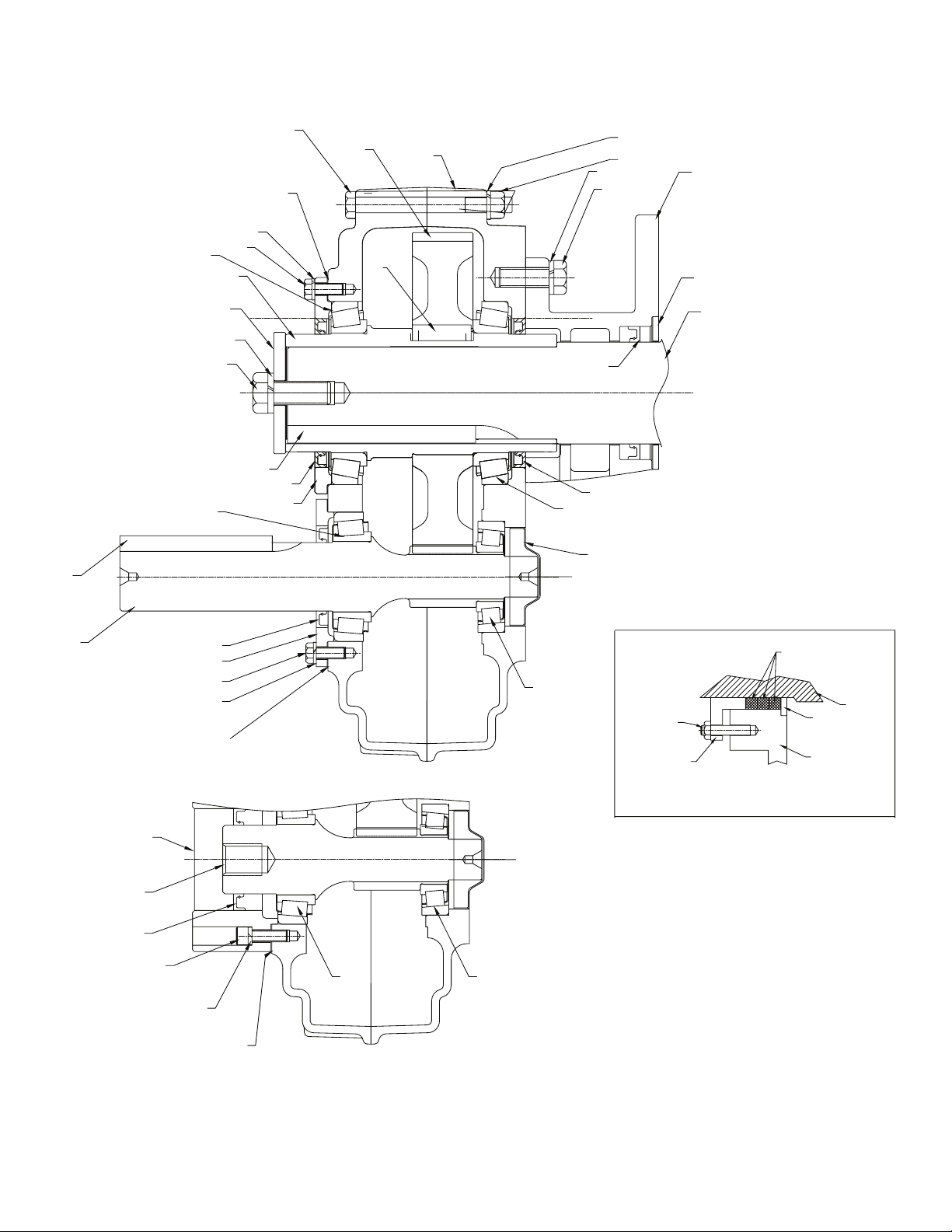
REPLACEMENT OF PARTS
IMPORTANT: Using tools normally found in a maintenance
department, a Dodge (H)SCXT speed reducer can be
disassembled and reassembled by careful attention to the
instructions following.
Cleanliness is very important to prevent the introduction of dirt
into the bearings and other parts of the reducer. A tank of clean
solvent, an arbor press, and equipment for heating bearings and
gears (for shrinking these parts on shafts) should be available.
The oil seals are contact lip seals. Considerable care should be
used during disassembly and reassembly to avoid damage to the
surface on which the seals rub.
The keyseat in the input shaft, as well as any sharp edges on
the output hub should be covered with tape or paper before
disassembly or reassembly. Also, be careful to remove any
burrs or nicks on surfaces of the input shaft or output hub before
disassembly or reassembly.
Ordering Parts: When ordering parts for reducer, specify
reducer size number, reducer model number, part name, part
number, and quantity.
It is strongly recommended that, when a pinion or gear is
replaced, the mating pinion or gear is replaced as well. If the large
gear on the output hub must be replaced, it is recommended
that an output hub assembly consisting of a gear assembled
on a hub be ordered to ensure undamaged surfaces on the
output hub where the output seals rub. However, if it is desired
to use the old output hub, press the gear and bearing o and
examine the rubbing surface under the oil seal carefully for
possible scratching or other damage resulting from the pressing
operation. To prevent oil leakage at the shaft oil seals, the smooth
surface of the output hub must not be damaged.
If any parts must be pressed from a shaft or from the output hub,
this should be done before ordering parts to make sure that none
of the bearings or other parts are damaged in removal. Do not
press against rollers or cage of any bearing.
Because old shaft oil seals may be damaged in disassembly, it is
advisable to order replacements for these parts.
Removing Screw Conveyor Drive from Trough End
Disconnect an electrical power to the drive. Drain lubricant from
reducer. Uncouple drive shaft and screw. Remove nuts from
trough end studs. Support drive by means of hoist and carefully
pull unit away from trough end to slide drive shaft out of screw.
Disassembly
1. Remove retainer bolt, lockwasher, and shaft retainer from
drive shaft. Pull drive shaft out of reducer from adapter side.
Remove adapter.
2. Position the reducer on its side and remove all housing
bolts. Drive dowel pins from housing. Using the three pry
slots around the periphery of the ange, gently separate the
housing halves. Open housing evenly to prevent damage to
the parts inside.
3. Lift input shaft, all gear assemblies, and bearing assemblies
from housing.
4. Remove seals from housing.
5. Remove bearings from shafts and hubs. Be careful not to
scratch or damage any assembly or seal area during bearing
removal. The hub assembly can be disassembled for gear
replacement but if scratching or grooving occurs on the hub,
seal leakage will occur and the hub will need to be replaced.
Reassembly
1. Output Hub Assembly: Heat gear to 325°F to 350°F to
shrink onto hub. Heat bearings to 270°F to 290°F to shrink
onto hub. Any damage to the hub surfaces where the oil seals
rub will cause leakage, making it necessary to replace the
hub.
2. Input Shaft Assembly: Heat bearings 270°F to 290°F to
shrink onto shaft. Press bearings on shaft.
3. Drive the two dowel pins into place in the right-hand housing
half (backstop side).
4. Place right-hand housing half on blocks to allow for protruding
end of output hub.
5. Install all bearing cups in right-hand housing half, making sure
they are properly seated.
6. Mesh the output hub gear and input shaft assembly together
and set in place in housing. Make sure bearing rollers (cones)

7MN16042
are properly seated in their cups. Set bearing cups for left-
hand housing half in place on their rollers.
7. Make sure both housing halves are clean and free of
RTV residue. For (H)SCXT 505E through 705E, apply a
continuous 1/8” diameter bead of Dow Corning RTV732
sealant on the ange surface of the right-hand housing (make
sure RTV is placed around all bolt holes). Do not apply RTV
sealant to (H)SCXT 305E and 405E reducers at this time. Set
the left-hand housing half in position onto the dowel pins and
gently tap with a soft hammer until housing bolts can be used
to draw housing halves together. Make sure reducer shafts do
not bind when tightening housing bolts. Torque housing bolts
per torque values listed in Table 5.
8. For (H)SCXT sizes 305E and 405E, rotate the input shaft and
set all bearings with a soft hammer. Using a magnetic base
and indicator, measure and record the endplay of the input
shaft and output hub. Remove the left housing half and shim
behind the bearing cup as required to achieve the correct
bearing endplay per Table 4. Repeat this process and check
endplay until proper endplay is obtained.
9. For (H)SCXT sizes 505E through 705E, install the output
seal carrier and draw down with two bolts 180° apart to 50
inch-pounds of torque. Loosen both bolts then retighten
nger-tight only. Measure the clearance between the housing
and carrier ange at each bolt and average the two values.
Add 0.010” to the average reading and make up shim pack.
Install shim pack between the carrier ange and reducer
housing. Torque the bolts to the value shown in Table 6. Using
a magnetic base and dial indicator, check the axial endplay
reading of the output hub is per Table 4.
10. For (H)SCXT 305E and 405E reducers, follow assembly
instructions for housing halves, including sealant, then
continue to step 11. For (H)SCXT 505E through 705E
reducers, repeat step 9 for installing and adjusting the input
bearings. Adjust the axial endplay per Table 4 then continue
to step 10.
11. Install input and output seals. Lightly coat the seal lips
with Mobilith AW2 All-Purpose grease or equivalent. The
possibility of damage and consequent oil leakage can be
decreased by covering all sharp edges with tape prior to seal
installation. Seals should be pressed or tapped with a soft
hammer evenly into place in the reducer housing, applying
pressure only on the outer edge of the seals.
NOTE: Extreme care should be used when installing
seals to avoid damage due to contact with sharp edges
on the input shaft or output hub. A slight oil leak at the
seals may be evident during initial running but should
disappear unless seals have been damaged.
12. Install backstop cover. Make sure all bolts, if applicable, are
tightened to the correct torque values listed in Table 5.
Table 4–Bearing Adjustment Tolerances
Reducer Size
Bearing Endplay Values
Input Output
(H)SCXT305E .002–.004 Loose .0005–.003 Loose
(H)SCXT405E .002–.004 Loose .0005–.003 Loose
(H)SCXT505E .002–.004 Loose .0005–.003 Loose
SCXT605E .002–.004 Loose .0005–.003 Loose
SCXT705E .002–.004 Loose .0005–.003 Loose
Table 5–Recommended Bolt Torque Values
Recommended Torque Values (ft-lbs)
Reducer Size Housing
Bolts
Output
Seal
Carrier
Input Seal
Carrier
Hydroil
Motor
Adapter
(H)SCXT305E 45–50 N/A N/A 27–30
(H)SCXT405E 45–50 N/A N/A 27–30
(H)SCXT505E 68–75 27–30 27–30 27–30
SCXT605E 68–75 27–30 27–30 N/A
SCXT705E 135–150 45–50 45–50 N/A
Recommended Torque (ft-lbs)
Reducer Size Drive Shaft Adapter Bolts Backstop
Cover
(H)SCXT305E 234–260 68–75 N/A
(H)SCXT405E 234–260 135–150 N/A
(H)SCXT505E 234–260 135–150 N/A
SCXT605E 576–640 135–150 7–8
SCXT705E 576–640 135–150 7–8
Table 6–Part Numbers for Replacement Bearings,
Single Reduction Reducers
Reducer Size
Output Hub
Bearing – Both
Sides
Input Shaft
Bearing – LH
Input Side
Input Shaft
Bearing – RH
Backstop Side
Dodge Part
Number
Dodge Part
Number
Dodge Part
Number
(H)SCXT305E Cone - 402272
Cup - 403127
Cone - 402190
Cup - 403132
Cone - 402271
Cup - 403101
(H)SCXT405E Cone - 402268
Cup - 403163
Cone - 402179
Cup - 403006
Cone - 402285
Cup - 403125
(H)SCXT505E Cone - 402193
Cup - 403016
Cone - 402270
Cup - 403026
Cone - 402266
Cup - 403073
SCXT605E Cone - 402050
Cup - 403140
Cone - 402053
Cup - 403106
Cone - 402123
Cup - 403009
SCXT705E Cone - 402058
Cup - 403111
Cone - 402057
Cup - 403143
Cone - 402078
Cup - 403034
Table 7–Replacement Parts Kit Numbers
Reducer Size Seal Kit Bearing Kit Complete Shim Kit
(H)SCXT305E 389726 392346 See Parts Breakdown
(H)SCXT405E 389727 392348 See Parts Breakdown
(H)SCXT505E 389728 392351 See Parts Breakdown
SCXT605E 272705 392352 246166
SCXT705E 247345 392354 240121
Table 8–Actual Ratios
Reducer Size
Nominal Ratio
5:1
TXT/HXT305E 5.60
TXT/HXT405E 5.65
TXT/HXT505E 5.67
TXT605E 5.67
TXT705E 5.36

8MN16042
Parts for (H)SCXT 305E and 405E Single Reduction Screw Conveyor and
Hydroil Screw Conveyor Drive
33
67
24
36
37
38
39
40
41
42
106
1
68
54
80
78
77
94
84
86
90
88
82
OPTIONAL ADJUSTABLE PACKING KIT
101
100 82
90
102
120
122
6
4
104
10
32
56
58
68
70
72
70
72
73
74
75
76 92
98
96
67
38
39
36
37
108
109
110
111
92

9MN16042
Ref. Description Qty (H)SCXT 305E (H)SCXT 405E
1
Housing Sub-Assembly
(SCXT) 1243278 244724
Housing Sub-Assembly
(HSCXT/HSCXT-6B) 1243723 244733
①Air Vent 1900287 900287
4Housing Bolt 7032018040NR 032018044NR
4Housing Bolt 1032018044NR 032018048NR
6Housing Lockwasher 8034017015AF 034017015AF
10 Housing Nut 8033102015AM 033102015AM
①RTV Sealant 1465044 465044
①Lifting Lug 1HA6360 HA6360
①Dowel Pin 2 420063 420063
①Magnetic Oil Plug 1430060 430060
①Oil Plug 3 430031 430031
①Smart Sensor Adapter 1966905 966905
①Shim Kit
24 RH Input Bearing Cover 1 253149 254275
32 Input Pinion 1253170 254230
33 Input Pinion Key 1 443078 443096
36 Input Bearing Cone,
Input Side 1402190 402179
37 Input Bearing Cup, Input
Side 1403132 403006
38 Input Bearing Cone
Backstop Side 1402271 402285
39 Input Bearing Cup
Backstop Side 1403101 403125
40 TXT305 or TXT405 EP
Input Shim (0.005") 2243732 244734
41 TXT305 or TXT405 EP
Input Shim (0.007") 1243733 244735
42 TXT305 or TXT405 EP
Input Shim (0.015") 1243734 244736
54 Output Hub - Straight
Bore 1243557 244589
56 Output Gear 1 243570 244188
58 Output Gear Key 1 243216 354087
Seal Kit ②1389726 389727
67 Input Pinion Shaft
Seal ③1351123 334277
68 Output Hub Oil Seal ③2902286 A73109
70 Output Bearing Cone 2 402272 402268
72 Output Bearing Cup 2 403127 403163
73 TXT3 Output Shim
(0.005") 2243633 244308
74 TXT3 Output Shim
(0.007") 1243634 244309
75 TXT3 Ouput Shim
(0.015") 1243635 244310
76 TXT3 Output Bearing
Spacer 1243636 244311
77 Retainer Bolt 1032020016FP 032020016FP
78 Lockwasher 1034017020AB 034017020AF
80 Driveshaft Retainer 1353053ZP 353088ZP
Adapter Assembly ②1353047 354121
82 Adapter ③ 1356164 356150
84 Bolt ③4032018012DR 032018014ER
86 Lockwasher ③4034017016AF 034017018AF
88 Lip Seal ③1353085 354115
90 Seal Retaining Ring ③1353054 354089
94 Driveshaft Key ③1443089 443114
Ref. Description Qty (H)SCXT 305E (H)SCXT 405E
92
Driveshafts
1-1/2" Diameter 1243562 244594
2" Diameter 1243563 244595
2-7/16" Diameter 1243564 244596
3" Diameter 1243565 244597
3-7/16" Diameter 1--- 244598
Adjustable Packing
Kit ②1356303 356304
100 Adjustable Packing
Retainer ③1356166 356152
101 SCXT/TAII Adjustable
Packing Hardware Kit③1356308 356308
102 AC3 or AC4 Packing
Rings (3 Pack) ③1427658PK3 427664PK3
96
Std Hydroil Input Pinion
(HSCXT) 1253171 254231
Hydroil 6B Input Pinion
(HSCXT-6B) 1253141 ---
98
Std Hydroil Motor
Adapter (HSCXT) 1253172 254222
Hydroil Motor Adapter
(HSCXT-6B) 1253142 ---
104
Adapter Screw, HSCXT ④032130014BF 032130018CF
Adapter Screw, HSCXT-
6B ④032130008BF ----
106 Adapter Lockwasher ④034020013AE 034020014AE
108 HSCXT Input Shim
(0.002") 2427853 254226
109 HSCXT Input Shim
(0.005") 1427854 254227
110 HSCXT Input Shim
(0.010") 1427855 254228
111 HSCXT Input Shim
(0.025") 1427856 254229
120
Hydroil Motor to Adapter
Screw (HSCXT) 4032018012DR 032018012DR
Hydroil Motor to Adapter
Screw (HSCXT-6B) 4032018012DR ----
122
Hydroil Motor to Adapter
Lock-washer (HSCXT) 3034017016AF 034017016AF
Hydroil Motor to Adapter
Lock-washer (HSCXT-
6B)
2034017016AF
①Not shown on drawing
②Includes parts listed immediately below
③Makes up assembly under which it is listed
④ 4 Required for HSCXT305E, 6 required for TXT405E
Parts for (H)SCXT 305E and 405E Single Reduction Screw Conveyor and
Hydroil Screw Conveyor Drive

10 MN16042
Parts for (H)SCXT 505E Double Reduction Screw Conveyor and
Hydroil Screw Conveyor Drive
24
38
39
30
66
64
28
34
37
36
74
66
64
6
10
33
104
106
67
96
102
62
54
1
88
84
86
76
78
80
94
90
82
101
100 82
90
102
4
32
68 68
72
70
70
72
56
58
92
92
38
39
36
37
30

11 MN16042
Ref. Description Qty (H)SCXT505E
1Housing Sub-Assembly
(SCXT/HSCXT) 1245682
①Air Vent 1904287
4Housing Bolt 7032018040DR
4Housing Bolt 1032018044DR
6Housing Lockwasher 8034017016AF
10 Housing Nut 8033102016AM
①RTV Sealant 1465044
①Lifting Lug 1HA6360
①Dowel Pin 2 304624
①Magnetic Oil Plug 1 430062
①Oil Plug 3430033
①Smart Sensor Adapter 1966906
24 Input RH Bearing Cover 1 245624
28 Input Shaft Seal Carrier 1255224
30 Input Shim Pack 2
sets 389725
32 Input Pinion 1255221
33 Input Pinion Key 1 443096
①Seal Kit ②1389728
34 Input Pinion Shaft Seal ③1245546
68 Output Hub Oil Seal ③2904286
36 Input Bearing Cone, Input Side 1 402270
37 Input Bearing Cup, Input Side 1 403026
38 Input Bearing Cone Backstop
Side 1402266
39 Input Bearing Cup Backstop
Side 1403073
54 Output Hub 1245591
56 Output Gear 1245186
58 Output Gear Key 1 355064
62 Output Seal Carrier 1255236
64 Seal Carrier Bolt 12 032018008CR
66 Seal Carrier Lock-washer 12 034017014AF
70 Output Bearing Cone 1 402193
72 Output Bearing Cup 1 403016
74 Output Hub Shim Pack 1 set 245139
76 Drive Shaft Bolt 1 032020016FP
78 Drive Shaft Lockwasher 1034017020AF
80 Drive Shaft Retainer 1355065ZP
Adapter Assembly ② 1355072
82 Adapter ③1356159
84 Bolt ③4032018014ER
86 Lockwasher ③4034017018AF
88 Lip Seal ③1355067
90 Seal Retaining Ring ③1355066
94 Driveshaft Key ③1443239
Ref. Description Qty (H)SCXT505E
Driveshafts
92
2" Diameter 1355175
2-7/16" Diameter 1355176
3" Diameter 1355177
3-7/16" Diameter 1355178
Adjustable Packing Kit ②1356305
100 Adjustable Packing Retainer ③1356101
101 SCXT/TAII Adjustable Packing
Hardware Kit③1356308
102 AC5 Packing Rings (3 Pack) ③1427674PK3
96 Hydroil Input Pinion 1255222
102 Hydraulic (Hydroil) Motor
Adapter 1255226
104 Adapter Screw, HSCXT 6 032130018CF
106 Lock-washer, HSCXT 6034020014AE
①Hydroil Motor to Adapter
Screw 4032018012DR
①Hydroil Motor to Adapter Lock-
washer 4034017016AF
① Not shown on drawing
②Includes parts listed immediately below
③ Makes up assembly under which it is listed
Parts for (H)SCXT 505E Double Reduction Screw Conveyor and
Hydroil Screw Conveyor Drive

12 MN16042
Parts for SCXT 605E and 705E Single Reduction Screw Conveyor
and Hydroil Screw Conveyor Drive
REVISION-
TITLEBLOCKNAME:
26
32
30
28
78
42
44
4
6
68
86
84
38
40
35
22
36
37
80
82
82
82
70
94
108
96
104
102
100
98
80
80
112
112
110
96
104
114
1
10
78
34
86
84
66
74
76
88
92
90 106
24
106
Parts for SCXT 605E and 705E Single Reduction Screw Conveyor Drive

13 MN16042
Ref. Description Qty SCXT605E SCXT705E
1Housing Sub-
Assembly (SCXT) 1246793 247679
4Housing Bolt 6032018044DR 032018048FR
4Housing Bolt 2032018048DR 032018052FR
6Lock-washer 8034017016AF 034017020AF
10 Hex Nut 8033102016AM 033102020AM
①RTV Sealant 1465044 465044
①Air Vent 1904287 904287
①Air Vent Adapter 1 --- 430079
①Dowel Pin 2 304624 304624
①Lifting Lug 2HA6360 021789
①Magnetic Oil Plug 1 430062 430064
①Oil Plug 4430033 430035
①Smart Sensor Adapter 1966906 966907
22 Input Shaft Seal
Carrier 1246184 257045
Shim Kit ②1 set 246166 240121
24 Input Shim Pack ③ ③ ③
88 Output Shim Pack ③ ③ ③
26 Backstop Cover 1 246221 247221
Seal Kit ②1272705 247345
28 Backstop Cover
Gasket ③1246220 246220
36 Input Pinion Shaft
Seal ③1256032 242113
78 Output Hub Oil Seal ③2905286 247310
30 Backstop Cover
Screw 6032018010AR 032018008AR
32 Backstop Cover Lock-
washer 6034017012AF 034017012AF
34 Input Pinion 1 256028 257044
35 Input Pinion Key 1 443113 443127
37 Input Bearing Spacer,
Input Side 1256030 ---
38 Input Bearing Cone,
Input Side 1402053 402057
40 Input Bearing Cup,
Input Side 1403106 403143
42 Input Bearing Cone
Backstop Side 1402123 402078
44 Input Bearing Cup
Backstop Side 1403009 403034
Output Hub
Assembly ②1390988 390990
66 Output Hub ③ 1246338 247338
68 Output Gear ③ 1246295 247215
70 Output Gear Key ③ 2245217 245217
74 Output Hub Seal
Carrier, Input Side 1246187 247315
76 Output Hub Seal
Carrier, Backstop Side 1246186 247315
80 Seal Carrier Bolt ④032018010CR 032018010NR
Ref. Description Qty SCXT605E SCXT705E
82 Seal Carrier Lock-
washer ④034017014AF 034017015AF
84 Output Bearing Cone 2 402050 402058
86 Output Bearing Cup 2 403140 403111
90 Driveshaft Retainer
Bolt 1032020020HP 032020020HP
92 Driveshaft Retainer
Lockwasher 1034017024AF 034017024AF
94 Driveshaft Retainer 1356047 356191
Adapter Assembly ②1356055 356187
96 Adapter ③1356155 356193
98 Bolt ③4032018020ER 032018024FR
100 Lockwasher ③4034017018AF 034017020AF
102 Lip Seal ③1355054 355054
104 Seal Retaining Ring ③1356054 356054
108 Driveshaft Key ③1443288 443288
Driveshafts
106
2-7/16" Diameter 1356042 356182
3" Diameter 1356043 356183
3-7/16" Diameter 1356044 356184
Adjustable Packing
Kit ② 1356306 356306
110 Adjustable Packing
Retainer ③1356157 356157
112
SCXT/TAII Adjustable
Packing Hardware
Kit③
1356308 356308
114 AC6/AC7 Packing
Rings (3 Pack) ③1427687PK3 427687PK3
①Not shown on drawing
②Includes parts listed immediately below
③Makes up assembly under which it is listed
④ 18 Required for TXT605E, 22 Required for TXT705E
Parts for SCXT 605E and 705E Single Reduction Screw Conveyor
and Hydroil Screw Conveyor Drive

14 MN16042

15 MN16042

Dodge Industrial, Inc.
1061 Holland Road
Simpsonville, SC 29681
+1 864 297 4800
All Rights Reserved. Printed in USA.
MN16042 10/22
*16042-1022
© DODGE INDUSTRIAL, INC.
AN RBC BEARINGS COMPANY
This manual suits for next models
7
Table of contents