Dodge ACR User manual

Owner’s Manual


This booklet is a supplement to your Viper SRT10 Owner’s Manual.
Please review the Owner’s Manual in addition to this booklet.
1.0 Overview
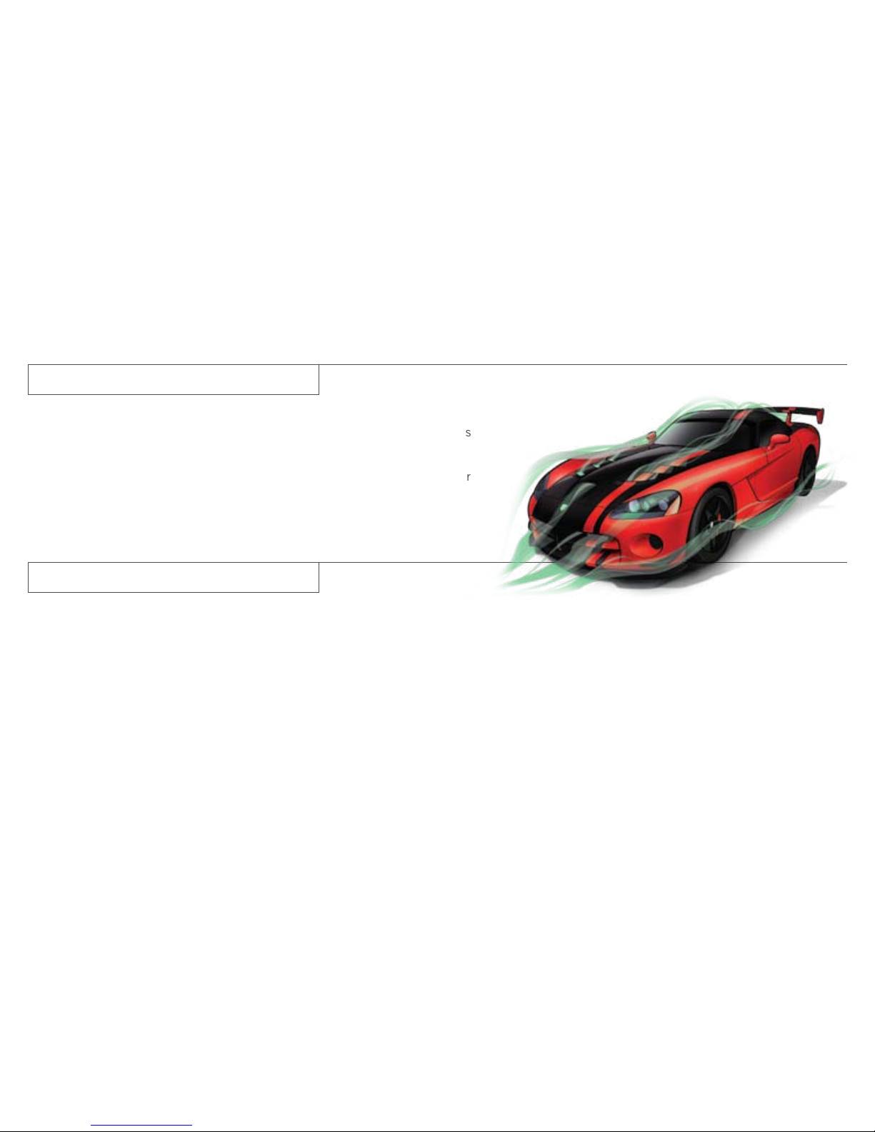
The Viper ACR is the literal fusion of Street and Racing Technology. It takes
the awe inspiring performance capabilities of the Dodge Viper SRT10 to the
next level.
The Viper ACR is not certified as a race car and it is not equipped with a
racing safety cage, racing restraints or other racing safety equipment.
Throughout this manual there are notes of WARNING and CAUTION. Review
each of them before driving this car.
WARNING: It is recommended that all customers complete a high-per-
formance driving school prior to operating this vehicle. Speeds at the
handling limits of this car are much higher than with other sports cars.
Competitive driving and track outings can cause serious injury or death.
Drive safely.

Splitters are potent aerodynamic elements usually only found
on purpose built racing cars. The Viper ACR front splitter has
been specially adapted for street use with the addition of several
new features.
•Theleadingedgehasbeenscallopedbacktoreducefront
overhang for day to day driving
•Toughenedpolymerrubstripshavebeenaddedtoreducewear
and abrasion on the splitter panel
•Tensioncablessupportthefrontedgetoallowsomeupward
deflection in minor impacts with ramped surfaces
In spite of these enhancements, the splitter remains highly vulnerable
to impact because of its position on the car.
The front splitter will not flex or compress against impacts from the
front. If an impact does occur, have the splitter inspected. A cracked
or delaminated splitter should be replaced.
The Viper ACR aerodynamics are capable of high levels of downforce
which will noticeably affect the grip and handling of the vehicle at speeds
as low as 50 mph.
Regularly inspect all of the aerodynamic components and attachments for
damage or wear.
2.1 Front Splitter
2.0 Aerodynamics

Always leave ample room and be sure to educate
anyone you allow to operate the vehicle.
CAUTION: Use care when approaching parking blocks,
tall speed bumps and garage curbs. These surfaces
can severely damage your splitter.
Use care when driving up to sloped surfaces or over
speed bumps. Approaching a speed bump or a slope
at a slight angle may improve your clearance.
CAUTION: Hard contact with steep ramps may cause
damage to your splitter.

The front of the ACR splitter is supported by two stainless
steel cables. These cables and their attachments should be
regularly inspected.
The splitter cables have an adjustment capability, however it
is recommended to leave the splitter at the factory delivered
settings. The splitter cables may have some slack while the
vehicle is at rest. When the splitter is loaded, and the cables
are under tension, the panel should be approximately parallel
to the bottom of frame.
Solid polymer rub strips are attached to the leading edge of
the splitter panel. Regularly inspect these rub strips to avoid
damage to the carbon fiber splitter panel.
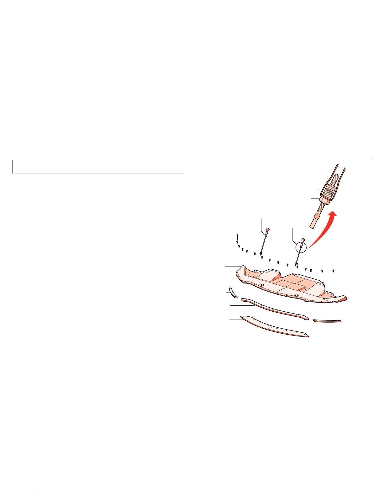
2.2 Splitter Components
Lock Nut
Length
Adjustment
Adjustment Nut
Splitter Panel
Center Rub Strip
Side Rub Strip
Track Extension
Splitter Cable
Screws

3/8” (10 mm)
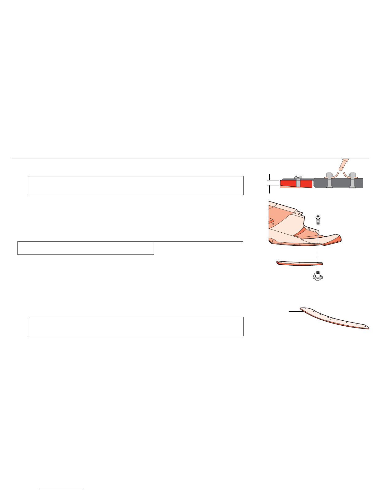
CAUTION: Replace rub strips when they are worn down to 3/8 in. (10 mm) on the front
edge. This will avoid damage to the carbon fiber panel.
Regularly inspect the outboard knock-in threaded insert to avoid premature splitter wear
(right and left side). Replace these fasteners as needed in order to protect the carbon
fiber splitter panel.
A splitter track extension is included in the trunk of every Viper ACR. The track extension
is mounted in the same location as the center rub strip. The on-track aerodynamic
balance was optimized with the track extension in place.
To install the track extension, remove the eight (8) screws of the center rub strip and
install the extension in the same mounting locations.
Tighten fasteners to 70 in-lbs (7.9 N·m).
CAUTION: The track extension should only be used during closed circuit track events. The
track extension can cause premature damage to your vehicle if used on public roads.
2.3 Track Extension
Lock Nut
Length
Adjustment
Adjustment Nut
Splitter Panel
Center Rub Strip
Side Rub Strip
Track Extension
Splitter Cable
Screws

The ACR rear wing generates most of the car’s aerodynamic downforce.
The wing is a powerful element that will affect the handling of the car
at speeds greater than 50 mph. Extreme caution should be given to any
modifications to the factory settings.
WARNING: Do not operate the vehicle with the rear wing removed.
The aerodynamic balance of this setup is unstable and can cause
the loss of control.
Regularly inspect the wing panel and attachment points for damage
or looseness.
The Viper ACR on-track aerodynamics have been tuned and balanced
for the vehicle with the track extension installed.
Wing Stanchions
The wing stanchions are designed with adjustment capability but they
are delivered locked with tamper resistant fasteners.
The wing is delivered from the factory in hole position 2.
2.4 Rear Wing
Wing setting as delivered

Wing Adjustment
It is possible to adjust the wing using the hole pattern at the top front of
the stanchion.
Note: Adjustment to the wing setting is not recommended.
The wing is attached to the lower stanchions with thread locker and tamper
resistant fasteners. The warranty does not cover any modifications or
removal of these wing fasteners.
In general, moving the wing up (e.g. Hole 2 to Hole 1) will decrease
rear down force and decrease overall understeer. Moving the wing down
(e.g. Hole 2 to Hole 3) will increase understeer.
Each successive hole increases the wing angle of attack by 1.5 degrees.
Adjustment
hole numbering
Example: Hole 4

The ACR aerodynamic components are made from prepreg autoclaved
carbon fiber. Both woven and unidirectional materials are used.
The clear coated carbon fiber panels will have some variation and minor
waviness in the woven pattern. This is inherent to the process and a sign
of its authenticity.
All carbon fiber materials are susceptible to UV degradation during long
exposure to the sun. The ACR woven carbon components use the latest
technology for both the resin system and the clear coat. As with any
automotive coating, storing your vehicle in a covered location will guarantee
a long lasting finish.
The rear wing on the non two-tone ACR is molded completely with
unidirectional carbon fiber and painted in body color. Some patterned or
linear conditions may be visible in the painted carbon fiber surfaces. This
is also a normal result of the carbon fiber process.
2.5 Carbon Fiber

The Viper SRT10 is known for having world class brakes. The 2008 Viper
ACR takes this incredible braking system to the next level with the Stop
Tech two-piece lightweight slotted rotors. These brake rotors significantly
reduce rotating un-sprung mass. They also improve brake cooling and
reduce on-track fade.
CAUTION: The slotted rotors may increase brake pad wear depending on
driving conditions. These rotors may also produce some additional brake
noise due to the high performance two-piece construction.
It is normal for the brakes to make some popping or creaking noises as they
cool down. This is the result of the two-piece construction.
Although the brake rotors are a two-piece construction, they should be
replaced as a complete assembly.
CAUTION: During brake pad replacement the pads must be loaded so that
the wear sensor is on the inboard side of the caliper and the trailing side of
the wheel rotation (all four wheels).
3.0 Two Piece Brake Rotors

•Trytoavoidabrupt,hardstopsfortherst200miles(300km)
•AvoidanyracingORoff-roadactivitiesfortherst200miles(300km)
•Avoidrepeatedincline/declinebrakingfortherst200miles(300km)
3.1 Street Break-in Procedure
CAUTION: Chrysler does not endorse speeding on public roads;
therefore, if a safe area cannot be used for break-in, you must
perform the street break-in procedure.
Regardless of completing the “street break-in procedure,”
this alternative break-in procedure is recommended before any
track use of the vehicle.
In the event that the street break-in procedure can’t be performed
before the pads and rotors are thermally stressed, use the following
procedure:
1. Read through the procedure and find a suitable, safe and legal
area to perform the necessary stops.
2. BEFORE starting the break-in procedure, drive with gentle
braking. Do not use brakes aggressively until performing
brake-in procedure.
3. Make a series of 10 stops from 60 to 5-10 MPH. At the end of
each stop, immediately accelerate to 60 again for the next stop.
Run all stops continuously in one cycle.
NOTE: A moderate braking effort is needed to properly break in the
rotors and pads. A stopping force of approximately 0.8G’s, just
short of ABS intervention, is the level of pedal effort you are trying
to attain.
4. During the 60 to 5-10 MPH series of stops, the exact speed is
not critical. Accelerate to approximately 60 and begin the braking
cycle. As you approach 5-10 MPH, it is not necessary to watch the
speedometer. Keep your eyes on the road and approximate your
speed at the end of each cycle.
CAUTION: Do not come to a complete stop! This will imprint pad
material onto the rotor, causing a vibration during future use.
3.2 Alternate Break in Procedure

5. Watch for the following:
•Onthe8thor9thstop,thereshouldbeadistinctsmellfromthe
brakes. Smoke may be evident during earlier stops as well.
•Alsoonthe8thor9thstop,somefrictionmaterialswill
experience “green fade”. This is a slight fading of the brakes.
The fade will stabilize, but not completely go away until the
brakes have cooled.
•Afterthebreak-incycleisnishedtherewillbealightgray
film on the rotor face. The gray film is pad material starting to
transfer onto the rotor face.
6. After the final stop, drive as much as possible without using the
brakes to cool off the system. Ideally, the brakes should be allowed
to cool to ambient temperature before using them again.
CAUTION: Do not come to a complete stop when the system is hot
and leave your foot on the pedal. Pad material will immediately
transfer to the rotor causing a vibration during future use.
7. After the first break in cycle, the brakes will still not be operating
at optimum capacity. A second or third heat cycle is typically
necessary before the brakes start to work optimally. This will occur
during everyday use.
3.3 Care and Maintenance
•Yourbrakecalipershaveapaintednish.Immediatelycleanoffany
spilled brake fluid, wiping it off with a soft, clean terry-cloth towel.
•Donotuseanyharshchemicalswhencleaningyourcalipers.Wash
your calipers with soap and rinse with water.
•Donotuseanyharshchemicalswhencleaningyourrotorhats(the
anodized center part of the rotor assembly). Wash your rotor hats
with soap and rinse with water.
•Breaking-inrotorsandpadsiscriticaltotheoptimumperformance
of your new brakes. When breaking-in new parts, you are not only
heat-cycling the pads, you are also depositing a layer of
pad material onto the rotor face. If not broken-in properly, an
uneven layer of pad material will be deposited onto the rotor,
causing vibration.
•Ifyouexperiencebrakepedalpulsation,steeringvibration,or
repeatable brake noise, perform the break-in procedure again as
soon as possible. This will re-condition the rotor surface and remove
irregular brake pad deposits. If concerns continue, please visit your
local dealer for further diagnosis.

YourViperACRcomesequippedwithMichelinPilotSportCup
competition oriented tires that are DOT approved for street use.
The Pilot Sport Cup tire uses a special tread and compound which
provides considerably more dry grip than normal street tires. Due to
the special tread and compound of your Pilot Sport Cup Tires, the
minimum tread depth can be reached earlier depending on your
driving style, resulting in reduced tire life. The special Pilot Sport Cup
tread and compound may lead to performance degradation in cold
climates, heavy rain or in conditions with standing water.
4.0 Pilot Sport Cup Tires
WARNING: Use extreme caution and drive slowly in wet situations
to reduce the risk of hydroplaning. Avoid driving in any conditions
of heavy rain or standing water. These conditions can cause loss of
control or accident.
WARNING: The Pilot Sport Cup tires were NOT intended to be driven
on snow or ice. The Pilot Sport Cup is a summer season tire and has
diminished capability on cold road surfaces (below 50ºF). DO NOT
OPERATE THE VEHICLE DURING THESE CONDITIONS. Snow, ice
and cold road surfaces can cause a loss of control or accident.

The Viper ACR suspension includes a set of adjustable coil-over
racing dampers built by KW Suspensions. These dampers have been
tuned by SRT handling engineers to provide the maximum handling
performance without sacrificing reasonable road manners.
The two-way adjustable dampers include adjustments for compression
(bump) and rebound dampening.
NOTE: Keep your damper settings at the street positions when
operating your vehicle on the street.
WARNING: Only experienced track drivers should make
adjustments to the suspension settings. Improper suspension
adjustment can disrupt the balance of the vehicle and lead to a
loss of control or accident.
CAUTION: Do not make any adjustments or modifications to the
nitrogen pressure of the damper canisters. This will void the warranty.
The ACR suspension was designed and tuned with an
uncompromising focus on handling. The ride response to road
conditions may be harsher than expected from a typical sports car.
5.0 Adjustable Dampers

Components
1. Spherical Bearing Mount
2. Rebound Adjuster
3. Upper Spring Seat
4. Primary Spring
5. Helper Spring
6. Lower Spring Seat
7. Compression Adjuster
8. Threaded Main Body
9. Reservoir
10. Spanner Wrench
11. Spring Seat Hex Wrench
YourViperACRisdeliveredwiththesuspensionadjustedfor
optimal street comfort. Below are the adjustment capabilities:
•CompressionDamping: 14 settings front and rear
•ReboundDamping: 19 settings front and rear
•RideHeight: +/- 1 ¼ in. (32 mm)
Any adjustments to the suspension settings should be made in
small increments.
CAUTION: The use of improper tools may severely damage your
suspension. The tools included with your Viper ACR are the
only tools that should be used for adjusting the ride height.
5.1 Damper Components

Components
1. Spherical Bearing Mount
2. Rebound Adjuster
3. Upper Spring Seat
4. Primary Spring
5. Helper Spring
6. Lower Spring Seat
7. Compression Adjuster
8. Threaded Main Body
9. Reservoir
10. Spanner Wrench
11. Spring Seat Hex Wrench
Adjusting the ride height:
1. Raise and support the vehicle. Both left and right side wheels should be lifted off the ground to allow
adjustment of the spring seats without damage. Never make ride height adjustments with the suspen-
sion loaded. The helper spring should never be fully compressed while adjusting ride heights.
2. Remove the wheel and tire assembly.
3. Loosen the set screw on the lower spring seat (approx 1 turn).
4. To lower the ride height, use the spanner wrench and rotate the lower spring seat counter-clockwise
(as viewed from below the damper). Use the set screw as a reference to return to street height.
5. To raise the ride height, first turn the seat in the counter-clockwise direction and ensure the threads
are clear of debris. Use the spanner wrench and reverse the direction.
6. Tighten the set screw to 22 in-lbs (2.5 N·m). DO NOT over tighten this screw.
The ride height adjustment sensitivity is as follows:
Front: One turn = 0.104 in. (2.6 mm) height change at frame
Rear: One turn = 0.134 in. (3.4 mm) height change at frame
5.2 Ride Height Adjustment
YourACRisdeliveredfromthefactoryatarideheightthatprovides
a good balance for drivability on the street. The adjustable suspen-
sion allows for ride height adjustment. As with all of the suspension
adjustments, caution should be used when changing the ride height.
CAUTION: Only the factory ride heights should be used while
operating the vehicle on the street. Low ride heights can cause
damage to the vehicle.
Before any adjustments are made to your ride height, clean threaded
area with soapy water to be sure it is free and clear of debris.

The compression adjustment (also called bump) varies the damping of the
upward travel of the wheel relative to the vehicle.
The compression adjuster is located on the remote canister fixed to the
damper body and has 14 damping positions. Depending on vehicle ride
height, the car may need to be raised to gain access to the compression
adjuster. To adjust the compression damping, turn the finger knob:
clockwise stiffens; counterclockwise softens when viewed from the top
surface of the finger knob.
All settings are referenced from the full stiff (position “0”). The “0”
position on compression is achieved by turning the finger knob clockwise
until you cannot turn it any further.
CAUTION: To avoid damage to your dampers DO NOT force the finger knob
when it stops turning. Also, NEVER use any tools to adjust the finger knob.
From the “0” position, turning the adjuster counterclockwise will soften
the damping. Count off the clicks and record your setting. Every “click” is
a new damping position (i.e. two clicks softer from the full stiff position is
position “2”).
5.3 Compression Adjustment
Soft Hard
Front
Rear
Hard Soft

5.4 Rebound Adjustment
Best Comfort is achieved at the following damper settings and
should always be used when driving on the street:
Front: Compression = Position “13”
Rebound = Position “18”
Rear: Compression = Position “13”
Rebound = Position “17”
5.5 Street Set up
The rebound adjustment (also called droop) varies the damping of the
downward travel of the wheel relative to the vehicle.
The rebound adjuster is located on top of the piston rod and has 19
damping positions. Depending on vehicle ride height, the car may
need to be raised to gain access to the rebound adjuster. To adjust
the rebound damping, turn the upper finger knob: clockwise stiffens;
counterclockwise softens when viewed from above.
All settings are referenced from the full stiff (position “0”). The “0”
position on rebound is achieved by turning the finger knob clockwise
until you cannot turn it any further.
CAUTION: To avoid damage to your
dampers DO NOT force the finger knob
when it stops turning. Also, NEVER use
any tools to adjust the finger knob.
From the “0” position, turning the adjuster
counterclockwise will soften the damping.
Every “click” is a new damping position
(i.e. two clicks softer from the full stiff
position is position “2”).
Hard Soft
+ –

Ride Height Adjustment
The factory ride height of your ACR is approximately:
Front: 5 ¼ in. (132 mm)
Rear: 6 in. (153 mm)
measured from the bottom of frame rail to ground at the axle
centerline with no passengers, a full tank of fuel and tire pressures
set to 29 psi.
A low ride height setting may not be optimal at all tracks. It will
generally be more acceptable to run a lower ride height at a track with
smoother surfaces, fewer abrupt elevation changes and fewer bumps.
The optimum set up for your vehicle also varies with track, driver and
ambient conditions. Below is a recommended starting point for two
typical track configurations.
Smooth track set up:
Front: 4 in. (102 mm)
Rear: 5 3/8 in. (136 mm)
Adjusting lower than then smooth track set up is not recommended.
Rough track set up:
Front: 4.375 in. (111 mm)
Rear: 5 1/2 in. (140 mm)
The rake of the car (or front to rear ride height difference) may also
be changed with your ACR suspension. Changing the rake may be
beneficial at some tracks. Use caution when changing the rake angle.
CAUTION: Depending on your set up, driving style, and track condition,
some tire to wheel liner contact may occur. To avoid excessive wheel
liner wear, adjust your ride height accordingly.
5.6 Track Set up
This manual suits for next models
1
Table of contents
Other Dodge Automobile Accessories manuals
Popular Automobile Accessories manuals by other brands

Directed
Directed Directechs DB3 installation guide

Painless Performance
Painless Performance 10309 instructions

Fortin
Fortin Evo One THAR-ONE-TOY1 SUGGESTED WIRING CONFIGURATION

Jaeger
Jaeger 21120524 Fitting instructions

HUSKY LINERS
HUSKY LINERS 2179FR Care and use instructions

Craftsman
Craftsman 50165 Operator's manual