Dodge HXT305A User manual

Parts Replacement Manual
For
HYDROIL
TORQUE-ARM
Speed Reducers
Taper Bushed
For Char-Lynn H, S, T and 2000 Series
6B Spline Motors
SIZES: HXT305A
HXT405A
HXT505A
WARNING: Because of the possible danger to persons(s) or property from accidents which may result from the improper use of products,
it is important that correct procedures be followed: Products must be used in accordance with the engineering information specified in the
catalog. Proper installation, maintenance and operation procedures must be observed. The instructions in the instruction manuals must be
followed. Inspections should be made as necessary to assure safe operation under prevailing conditions. Proper guards and other suitable
safety devices or procedures as may be desirable or as may be specified in safety codes should be provided, and are neither provided by
Baldor Electric Company nor are the responsibility of Baldor Electric Company. This unit and its associated equipment must be installed,
adjusted and maintained by qualified personnel who are familiar with the construction and operation of all equipment in the system and the
potential hazards involved. When risk to persons or property may be involved, a holding device must be an integral part of the driven
equipment beyond the speed reducer output shaft.
www.baldor.com www.ptplace.com www.dodge-pt.com www.reliance.com
Baldor Electric Company Headquarters
P.O. Box 2400, Fort Smith, AR 72902-2400 U.S.A., Ph: (1) 479.648.5792, Fax (1) 479.648.5792, International Fax (1) 479.648.5895
DODGE/Reliance Division
6040 Ponders Court, Greenville, SC 29615-4617 U.S.A., Ph: (1) 864.297.4800, FAX: (1) 864.281.2433
Copyright © 2007 Baldor Electric Company All Rights Reserved. Printed in USA.
04/07
1M-K
This material is not intended to provide operational instructions. Appropriate instruction
manuals and precautions should be studied prior to installation, operation or maintenance
of equipment.


3
REDUCER INSTALLATION
1. On sizes HXT305A, HXT405A, and HXT505A use
lifting lug to lift reducers.
2. Determine the running positions of the reducer.
(See Fig. 1) Note that the reducer is supplied with
either 4 or 7 plugs; 4 around the sides for
horizontal installations and 1 on each face for
vertical installations. These plugs must be
arranged relative to the running positions as
follows:
Horizontal Installations—Install the magnetic
drain plug in the hole closest to the bottom of the
reducer. Throw away the tape that covers the
filler/ventilation plug in shipment and install plug in
topmost hole. Of the 3 remaining plugs on the
sides of the reducer, the lowest one is the
minimum oil level plug.
CAUTION
Unit is shipped without oil. Add proper amount
of recommended lubricant before operating.
Failure to observe these precautions could
result in damage to, or destruction of, the
equipment.
The running position of the reducer in a
horizontal application is not limited to the four
positions shown in Figure 1. However, if running
position is over 20º either way from sketches, the
oil level, plug cannot be safely used to check the
oil level, unless during the checking the torque arm
is disconnected and the reducer is swung to within
20º in positions “B” and “D” or 5º in positions “A”
and “C” of the possible positions shown in Figure
1. Because of the many possible positions of the
reducer, it may be necessary or desirable to make
special adaptions using the lubrication fitting holes
furnished along with other standard pipe fittings,
stand pipes and oil level gages as required.
3. Mount Taper Bushed reducer on driven shaft per
instruction sheet No. 499629 packed with tapered
bushings.
4. Install torque arm and adapter plates using the
long reducer bolts. The bolts may be shifted to any
of the holes on the input end of the reducer.
5. Install torque arm fulcrum on a rigid support so that
the torque arm will be approximately at right angles
to the center line through the driven shaft and the
torque arm anchor screw.
CHAR-LYNN H, S, T AND 2000 SERIES
6B SPLINE MOTOR INSTALLATION
Consult the local Char-Lynn Motor dealer for
hydraulic motor information.
WARNING
To ensure that drive is not unexpectedly
started, turn off and lock out or tag power
source before proceeding. Failure to observe
these precautions could result in bodily injury.
REDUCER LUBRICATION
CAUTION
Extreme pressure (EP) lubricants are not
recommended for average operating conditions.
Failure to observe these precautions could result
in damage to, or destruction of, the equipment.
Important: Because reducer is shipped without oil, it
is necessary to add the proper amount of oil before
running. Use a high grade petroleum base, rust and
oxidation inhibited (R & O) gear oil—see tables.
Follow instructions on reducer nameplate, warning
tags, and in the installation manual.
Under average industrial operating conditions, the
lubricant should be changed every 2500 hours of
operation or every 6 months, whichever occurs first.
Drain reducer and flush with kerosene, clean
magnetic drain plug and refill to proper level with new
lubricant.
CAUTION
Do not use oils containing slippery additives
such as graphite or molybdenum disulphide in
the reducer when backstop is used. These
additives will destroy sprag action. Failure to
observe these precautions could result in
damage to, or destruction of, the equipment.
CAUTION
Too much oil will cause overheating and too little
will result in gear failure. Check oil level regularly.
Failure to observe this precaution could result in
damage to or destruction of the equipment
Under extreme operating conditions, such as rapid
rise and fall of temperature, dust, dirt, chemical
particles, chemical fumes, or oil sump temperatures
above 200ºF, the oil should be changed every 1 to 3
months depending on severity of conditions.

4
Table 1 – Oil Volumes Volume of Oil Required to Fill Reducer to Oil Level Plug
† Position A † Position B † Position C † Position D
Reducer
Size Fluid
Ounces
(Approx)
S
Quarts
(Approx)
Liters
(Approx)
Fluid
Ounces
(Approx)
S
Quarts
(Approx)
Liters
(Approx)
Fluid
Ounces
(Approx)
S
Quarts
(Approx)
Liters
(Approx)
Fluid
Ounces
(Approx)
S
Quarts
(Approx)
Liters
(Approx)
HXT305A 28 7/8 .83 48 1½ 1.42 44 13/81.30 44 13/81.30
HXT405A 48 1½ 1.42 72 2¼ 2.13 68 21/82.01 60 17/81.77
HXT505A 108 33/83.19 136 4¼ 4.02 124 37/83.67 120 3¾ 3.54
† Refer to Fig. 1 on page 2 for mounting positions.
SU.S. Measure: 1 quart = 32 fluid ounces = .94646 liters.
Note: If reducer position is to vary from those shown in Figure 1
either more or less oil may be required. Consult factory.
Minimum Oil Recommendations for Average Operating Conditions
Table 2 — Lubrication Recommendations —
ISO Grades for Ambient Temperatures of 15º to 60º Table 3 — Lubrication Recommendations —
ISO Grades for Ambient Temperatures of 15º to 125º
Reducer Size Reducer Size
Output
RPM 1 2 3 4 5 6 7 8 9 10 12 13 14 15
Output
RPM 1 2 3 4 5 6 7 8 9 10 12 13 14 15
301–400 220 220 150 150 150 150 150 150 150 150 150 150 150 150 301–400 320 320 220 220 220 220 220 220 220 220 220 220 220 220
201–300 220 220 150 150 150 150 150 150 150 150 150 150 150 150 201–300 320 320 220 220 220 220 220 220 220 220 220 220 220 220
151–200 220 220 150 150 150 150 150 150 150 150 150 150 150 150 151–200 320 320 220 220 220 220 220 220 220 220 220 220 220 220
126–150 220 220 220 150 150 150 150 150 150 150 150 150 150 150 126–150 320 320 320 220 220 220 220 220 220 220 220 220 220 220
101–125 220 220 220 220 150 150 150 150 150 150 150 150 150 150 101–125 320 320 320 320 220 220 220 220 220 220 220 220 220 220
81–100 220 220 220 220 220 150 150 150 150 150 150 150 150 150 81–100 320 320 320 320 320 220 220 220 220 220 220 220 220 220
41–80 220 220 220 220 220 150 150 150 150 150 150 150 150 150 41–80 320 320 320 320 320 220 220 220 220 220 220 220 220 220
11–40 220 220 220 220 220 220 220 220 220 220 150 150 150 150 11–40 320 320 320 320 320 320 320 320 320 320 220 220 220 220
1–10 220 220 220 220 220 220 220 220 220 220 220 220 220 220 1–10 320 320 320 320 320 320 320 320 320 320 320 320 320 320
Below – 23ºF call application engineering.
20ºF to -22ºF use Mobil SHC 627.
Above 125ºF use Mobil SHC 634.
See page 8 for lubricant viscosity classification
equivalents.
NOTE:
Pour point of lubricant selected should be at least
10ºF lower than expected minimum ambient starting
temperature.
Special lubricants may be required for food and
drug industry applications where contact with the
product being manufactured may occur. Consult a
lubrication manufacturer’s representative for his
recommendation.
GUIDELINES FOR TORQUE-ARM REDUCER LONG-TERM STORAGE
During periods of long storage, or when waiting for
delivery or installation of other equipment, special
care should be taken to protect a gear reducer to have
it ready to be in the best condition when placed into
service.
By taking special precautions, problems such as
seal leakage and reducer failure due to the lack of
lubrication, improper lubrication quantity, or
contamination can be avoided. The following
precautions will protect gear reducers during periods
of extended storage:
Preparation
1. Drain the oil from the unit. Add a vapor phase
corrosion inhibiting oil (VCI–105 oil by Daubert
Chemical Co.) in accordance with Table 3.
2. Seal the unit air tight. Replace the vent plug with a
standard pipe plug and wire the vent to the unit.
3. Cover the shaft extension with a waxy rust
preventative compound that will keep oxygen away
from the bare metal. (Non-Rust X-110 by Daubert
Chemical Co.).
4. The instruction manuals and lubrication tags are
paper and must be kept dry. Either remove these
documents and store them inside or cover the unit
with a durable waterproof cover which can keep
moisture away.
5. Protect the reducer from dust, moisture, and other
contaminants by storing the unit in a dry area.
6. In damp environments, the reducer should be
packed inside a moisture-proof container or an
envelope of polyethylene containing a desiccant
material. If the reducer is to be stored outdoors,
cover the entire exterior with a rust preventative.
When Placing the Reducer into Service
1. Assemble the vent plug into the proper hole.
2. Clean the shaft extensions with petroleum
solvents.
3. Fill the unit to the proper oil level using a
recommended lubricant. The VCI oil will not affect
the new lubricant.
4. Follow the installation instructions provided in this
manual.
Table 4—Quantities of VCI #105 Oil
Case Size Quarts or Liters
HXT305A .1
HXT405A .2
HXT505A .3
VCI #105 & #10 are interchangeable.
VCI #105 is more readily available.

5
Note: The two-digit numbers are
for reference only. Order parts
by the six-digit numbers in the
Parts List. Each six-digit number
is a complete identification of the
part or assembly.

6
Refer-
ence Name of Part No.
Req’d. HXT305A
Part No. HXT405A
Part No. HXT505A
Part No.
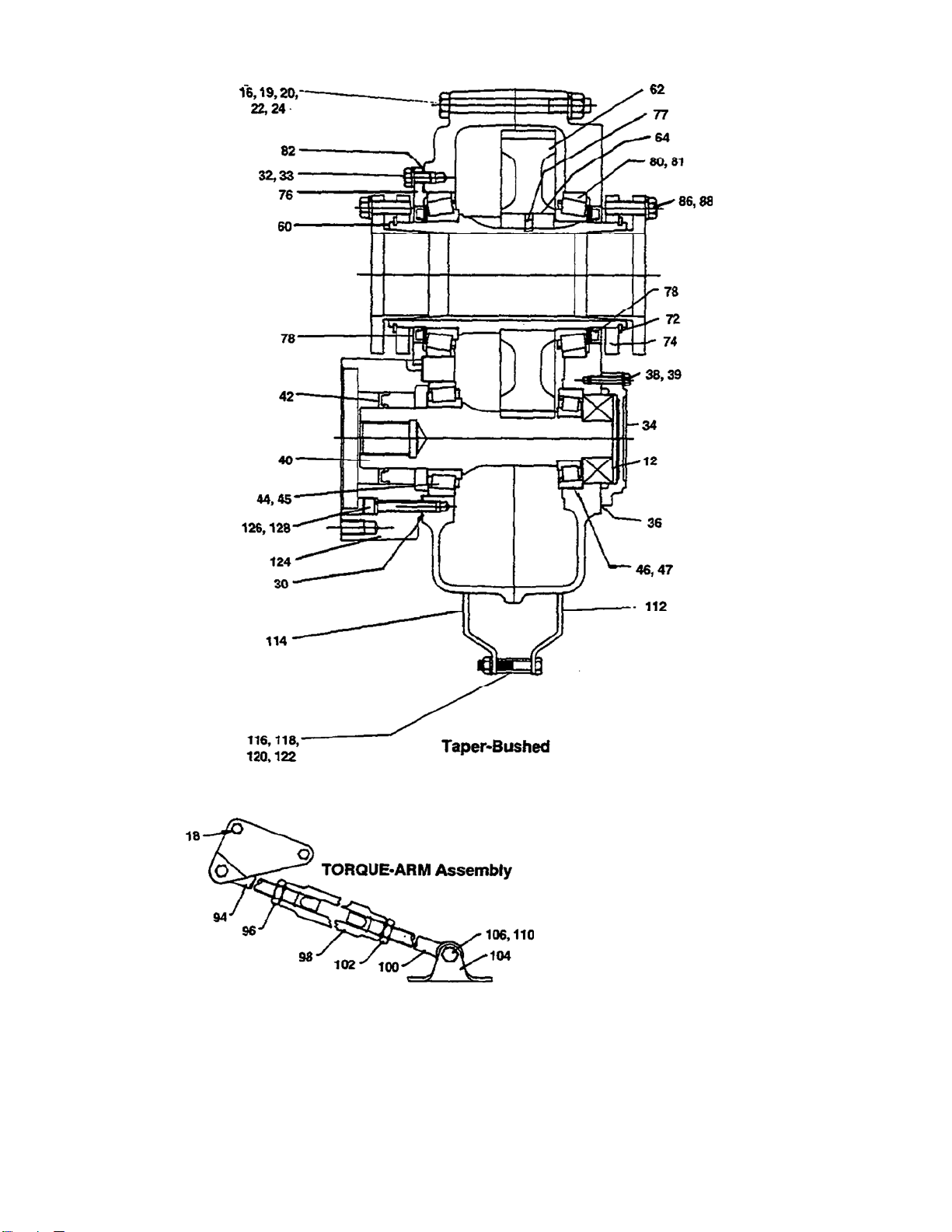
12 Backstop Assembly 1 243102 244148 245154
HOUSING 1 253165 254218 255216
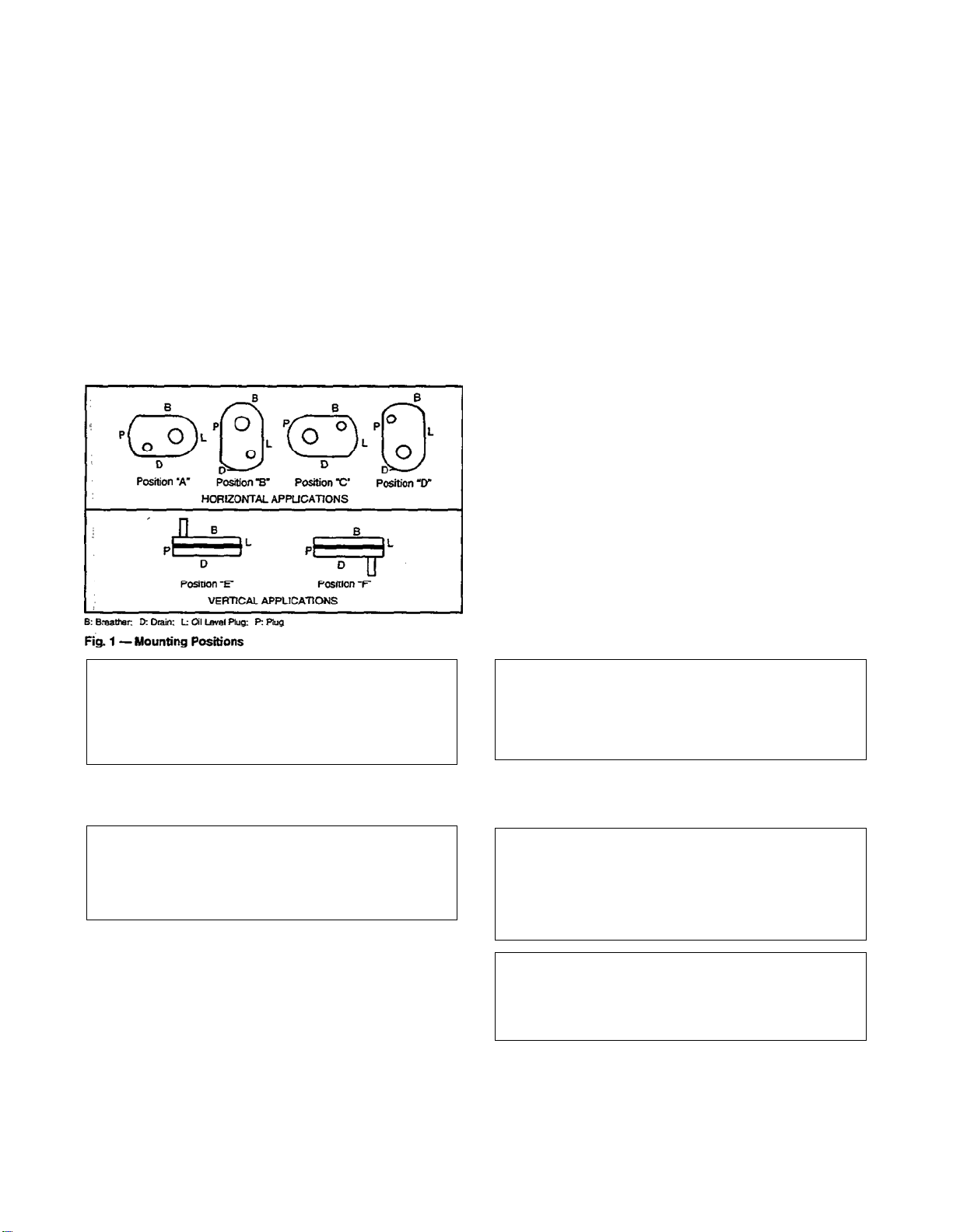
Air Vent 1 241237 241237 245237
16 Housing Bolt 6 411440 411442 411464
18 Adapter Housing Bolt 2 411442 411444 411466
19 Washer 4 419094 419094 419096
20 Lockwasher 6 419012 419012 419013
22 Hex Nut 8 407089 407089 407091
24 Dowel Pin 2 420055 420055 420110
Pipe Plug 2 430031 430031 430033
Magnetic Plug 1 430060 430060 430062
30* Input Shaft Bearing Shim Pack 2‡ 389723 389724 389725
.002" Thick † 427853 254226 427833
.005" Thick † 427854 254227 427834
.010" Thick † 427855 254228 427835
.025" Thick † 427856 254229 427836
32 Carrier and Cover Screws 10 411390 411407 411407
33 Lockwasher 10 419010 419011 419011
34 Backstop Cover 1 253175 254223 255019
38 Backstop Cover Screw 6 416524 411035 411406
39 Lockwasher 6 419007 419009 419009
40* Input Shaft with Pinion 1 253141 254141 255161
44* Input Shaft Brg. Cone 1 402190 402179 402270
45* (Input Side) Cup 1 403132 403006 403026
46* Input Shaft Brg. Cone 1 402271 402285 402266
47* (Backstop Side) Cup 1 403101 403125 403073
OUTPUT HUB
ASSEMBLYTaper Bushed 1 389703 389710 389717
60* cOutput
Hub Taper Bushed 1 243556 244588 245590
62* cOutput Gear 1 243570 244188 245186
64* cOutput Gear Key 2 243216 244217 355064
72 Bushing Back-up Plate 2 243308 244099 245114
74 Retaining Ring 2 421109 421108 421107
76 Output Hub Seal Carrier (Input
Side) 1 243547 244591 245592
77 Roll Pin 1 409022 409022 409022
80* Output Hub Cone 2 402272 402268 402193
81* Bearing Cup 2 403127 403163 403016
82* Output Hub Bearing Shim Pack 2‡ 389706 389713 389719
.002" Thick † 427849 244616 427825
.005" Thick † 427850 244617 427826
.010" Thick † 427851 244618 427827
.025" Thick † 427852 244619 427828
SEAL KIT* 1 389726 389727 389728
36* cBackstop Cover Gasket 1 253176 254221 255020
42* cInput Shaft Seal 1 351123 355011 245546
78* cOutput Hub Seal 2 243578 244673 245545
RTV Sealant, Tube 1 465044 465044 465044
Includes parts listed immediately below marked “c.” HXT505A housing
assembly also includes a two-piece housing. Bushing assemblies include 2
bushings.
cParts marked “c” make up the assemblies under which they are listed.
Not shown on drawing.
‡One set consists of one each of the shims listed immediately below marked “†.”
†See last paragraph under “ORDERING PARTS.”
Refer-
ence Name of Part No.
Req’d. HXT305
A
Part No. HXT405
A
Part No. HXT505
A
Part No.
1
5/16" Bore 1 243282 ...... ......
1
3/8" Bore 1 243284 ...... ......
1
7/16" Bore 1 243260 244079 ......
1½" Bore 1 243262 244081 ......
1
5/8" Bore 1 243264 244083 ......
1
11/16" Bore 1 243268 244085 ......
1¾" Bore 1 243266 244087 ......
1
7/8" Bore 1 243270 244089 245084
84 BUSHING 115/16" Bore 1 243272 244093 245086
ASSEMBLY 2" Bore 1 243274 244095 245088
2
1/8" Bore 1 ...... 244109 ......
2
3/16" Bore 1 243276 244111 245090
2¼" Bore 1 ...... 244113 245092
2
7/16" Bore 1 ...... 244115 245094
2½" Bore 1 ...... ...... 245099
2
11/16" Bore 1 ...... ...... 245110
2
15/16" Bore 1 ...... ...... 245112
86 cBushing Screw 6 411407 411408 411435
88 cLockwasher 6 419011 419011 419012
1
5/16" Bore 1 443264 ...... ......
1
3/8" Bore 1 443264 ...... ......
1
7/16" Bore 1 443265 443254 ......
1½" Bore 1 443265 443254 ......
1
5/8" Bore 1 443265 443254 ......
1
11/16" Bore 1 443266 443254 ......
1¾" Bore 1 443266 443254 ......
90 cKey, Bushing 17/8" Bore 1 443267 443255 443251
to Shaft 115/16" Bore 1 443269 443255 443251
2" Bore 1 443268 443255 443251
2
1/8" Bore 1 ...... 443258 ......
2
3/16" Bore 1 443270 443259 443251
2¼" Bore 1 ...... 443260 443251
2
7/16" Bore 1 ...... 443261 443243
2½" Bore 1 ...... ...... 443244
2
11/16" Bore 1 ...... ...... 443245
2
15/16" Bore 1 ...... ...... 443250
cKey, Bushing to Output Hub 1ß 443262 443257 443202
cKey, Bushing to Output Hub 1λ...... 443256 ......
TORQUE-ARM ASSEMBLY1 243097 245097 245097
94 cRod End 1 243245 245245 245245
96 cHex Nut 1 407095 407097 407097
98 cTumbuckle 1 243246 245246 245246
100 cExtension 1 243247 245247 245247
102 cL.H. Hex Nut 1 407244 407246 407246
104 cFulcrum 1 243249 246249 246249
106 cFulcrum Screw 1 411484 411484 411484
110 cHex Nut 1 407093 407093 407093
ADAPTER ASSEMBLY1 259153 259154 259155
112 cR.H. Adapter Plate 1 243242 244244 245242
114 cL.H. Adapter Plate 1 243241 244243 245241
116 cAdapter Bushing 1 243243 245243 245243
118 cAdapter Bolt 1 411437 411460 411460
120 cLockwasher 1 419012 419013 419013
122 cHex Nut 1 407089 407091 407091
124 Motor Adapter 1 253142 254142 255162
126 Adapter Screw 4417081 417108 417108
128 Lockwasher 4419046 419047 419047
*Recommended spare parts
ßOn size HXT305A for 15/16" thru 1¾" bores; HXT405A for 17/18" thru
17/8" bores; HXT505A for 17/8" thru 2¼" bores.
λOne size — HXT405A for 115/16" bores and 2" bores.
Requires 5 bolts.
Table 5 — Manufacturers’ Part Numbers
For Replacement Output Hub Bearings
Output Hub BearingTORQUE-ARM Reducer
Drive
Size DODGE
Part Number Timken
Part Number
402272 LM814849
HXT305A 403127 LM814810
402268 498
HXT405A 403163 492A
402193 42381
HXT505A 403016 42584
Table 6 — Manufacturers’ Part Numbers
For Replacement Input Shaft Bearings
TORQUE-ARM
Reducer Input Bearing Input Side Input Bearing Adapter Side
Size DODGE Part
No. Timken Part
No. DODGE Part
No. Timken Part
No.
402190 LM603048 402271 02872
HXT305A 403132 LM603011 403101 02820
402179 368 402285 339
HXT405A 403006 362A 403125 332
402270 45289 402266 350A
HXT505A 403026 45220 403073 352

7
REPLACEMENT OF PARTS
A DODGE TORQUE-ARM Speed Reducer can be
disassembled and reassembled by careful attention to
the instructions following, using tools normally found
in a maintenance department.
Cleanliness is very important to prevent the
introduction of dirt into the bearings and other parts of
the reducer. A tank of clean solvent, an arbor press,
and equipment for heating bearings and gears should
be available for shrinking these parts on shafts.
Our factory is prepared to repair reducers for
customers who do not have proper facilities or who for
any reason desire factory service.
The oil seals are of the rubbing type and considerable
care should be used during disassembly and
reassembly to avoid damage to the surface on which
the seals rub.
The keyseat in the input shaft as well as any sharp
edges on the output hub should be covered with tape
or paper before disassembly or reassembly. Also be
careful to remove any burrs or nicks on surfaces of
the input shaft or output hub before disassembly or
reassembly.
ORDERING PARTS:
When ordering parts for reducer, specify reducer size
number, reducer serial number, part name, part
number and quantity.
It is strongly recommended that when a pinion or gear
is replaced, the mating gear or pinion be replaced
also.
If the large gear on the output hub must be replaced, it
is recommended that an output hub assembly with a
gear assembled on the hub be ordered to secure
undamaged surfaces on the output hub where the oil
seals rub. However, if it is desired to use the old
output hub, press the gear and bearing off and
examine the rubbing surface under the oil seal
carefully for possible scratching or other damage
resulting from the pressing operation. To prevent oil
leakage at the shaft oil seals the smooth surface of
the output hub must not be damaged.
If any parts must be pressed from a shaft or from the
output hub, this should be done before ordering parts
to make sure that none of the bearings or other parts
are damaged in removal. Do not press against outer
race of any bearing.
Because old shaft oil seals may be damaged in
disassembly it is advisable to order replacements for
these parts.
If replacing a bearing or a shaft, it is advisable to order
a set of shims for adjustment of bearings on the shaft
assembly. If replacing a housing, a set of shims
should be ordered for each shaft assembly because
the adjustment of the bearings on each shaft
assembly is affected.
REMOVING TAPER BUSHED REDUCER FROM SHAFT:
WARNING
To ensure that drive is not unexpectedly
started, turn off and lock out or tag power
source before proceeding. Failure to observe
these precautions could result in bodily injury.
WARNING
External loads may cause machine movement.
Block machine before removing any drive train
components. Failure to observe these precautions
could result in bodily injury.
1. Remove bushing screws.
2. Place the screws in the threaded holes provided in
the bushing flanges. Tighten the screws alternately
and evenly until the bushings are free on the shaft.
For ease of tightening screws make sure screw
threads and threaded holes in bushing flanges are
clean.
3. Remove the outside bushing, the reducer and then
the inboard bushing.
DISASSEMBLY:
1. Remove all bolts from housing. Drive back hollow
dowel pins on either side of housing. Remove
back-up plates and snap rings on the output hub
on taper-bushed reducers. Open housing evenly to
prevent damage to parts inside.
2. Lift shaft, gear and bearing assemblies from
housing.
3. Remove seals, seal carriers and bearing cups from
housing.
REASSEMBLY:
1. Output Hub Assembly: Heat gear to 325º to
350ºF for shrinking onto output hub. Heat bearing
cones to 270º to 290ºF for shrinking onto output
hub.
2. Input Shaft Assembly: Shaft and pinion are
integral. Heat bearing cones to 270º to 290ºF for
shrinking onto shaft.
3. Drive the dowel pins back into position in the right-
hand housing half. Place housing half on blocks to
allow for protruding end of output hub. Install
bearing cups in right-hand housing half making
sure they are properly seated.
4. Mesh output hub gear and input shaft assembly
together and set in place in housing. Make sure
bearing rollers (cones) are properly seated in their
cups. Set bearing cups for left-hand housing half in
place on their rollers.
5. Clean housing flange surfaces on both halves,
making sure not to nick or scratch flange face.
Place a new bead of gasket eliminator on flange
face and spread evenly over entire flange leaving
no bare spots. Place other housing half into
position and tap with a soft hammer (rawhide not
lead hammer) until housing bolts can be used or
draw housing halves together. Torque housing
bolts per torque values listed below.
6. Place output hub seal carrier in position without
shims and install two carrier screws diametrically
opposed. Torque each screw to 25 lb.-ins. Rotate
the output hub to roll in the bearings and then
torque each screw once to 50 lb.-ins. Do not
retorque screws.

8
Again turn output hub to roll in the bearings. With a
feeler or taper gage, measure the gap between the
housing and the carrier, clockwise from and next to
each screw. To determine the required shim
thickness, take the average of the two feeler gage
readings. Remove carrier and install the required
shims. Note: Total shim thickness per carrier
should not include more than .009" plastic shims
and each plastic shim should be inserted between
two metal shims. Place a 1/8" diameter bead of
Dow Corning RTV732 sealant on the face around
the I.D. of the end shim (sealant is to be between
reducer housing and shim) and install carrier on
reducer housing. Torque carrier bolts to value
shown in Table 7. Output hub should have an axial
end play of .001" to .003".
7. Using the same procedure as in step 6, adjust the
input shaft bearings, except the axial end play
should be .002" to .004".
Table 7 — Bolt Tightening Torque Values
Reducer
Size Housing Bolts
(in.-lbs.) Seal Carrier Bolts
(in.-lbs.)
HXT305A 600 204
HXT405A 600 360
HXT505A 900 360
8. Apply sealant to the input shaft cover gasket and
install input shaft cover in right-hand housing half.
Install input and output seals. Extreme care should
be used when installing seals to avoid damage due
to contact with sharp edges on the input shaft or
output hub. This danger of damage and consequent
oil leakage can be decreased by covering all sharp
edges with tape or paper prior to seal installation. Fill
cavity between seal lips with grease. Seals should be
pressed or tapped with a soft hammer evenly into
place in the carrier applying pressure only on the
outer edge of the seals. A slight oil leakage at the
seals may be evident during initial running in but
should disappear unless seals have been damaged.
9. Install bushing back-up plate and snap rings.

9
Viscosity Classification Equivalents
This manual suits for next models
2
Table of contents
Other Dodge Automobile Accessories manuals
Popular Automobile Accessories manuals by other brands

Directed
Directed Directechs DB3 installation guide

Painless Performance
Painless Performance 10309 instructions

Fortin
Fortin Evo One THAR-ONE-TOY1 SUGGESTED WIRING CONFIGURATION

Jaeger
Jaeger 21120524 Fitting instructions

HUSKY LINERS
HUSKY LINERS 2179FR Care and use instructions

Craftsman
Craftsman 50165 Operator's manual