Doepke Dupline DFA-DI User manual

3931200/02/05/C
Doepke
Dupline
Fernantrieb-Interface DFA-DI
Remote Actuator DFA-DI
Bedienungsanleitung
Operating Instructions

2 3931200/02/05/C
Doepke
Inhaltsverzeichnis
1. Allgemeines ........................................................................................... 3
2. Kodierung .............................................................................................. 3
4. Inbetriebnahme...................................................................................... 4
5. Garantie................................................................................................. 4
6. Technische Daten.................................................................................. 4
7. Anschlussschema.................................................................................. 5
8. Kontakt .................................................................................................. 5
Table of Contents
9. General Information............................................................................... 6
10. Coding ................................................................................................... 6
12. Putting into Service................................................................................ 7
13. Guarantee.............................................................................................. 7
14. Technical Data....................................................................................... 7
15. Connection Diagram.............................................................................. 8
16. Contact .................................................................................................. 8

3931200/02/05/C 3
Doepke
Bedienungsanleitung
Dupline Fernantrieb-Interface DFA-DI
1. Allgemeines
Das Dupline-Interface DFA-DI ist eine Komponente des Dupline Installationssystems
und ermöglicht die Ansteuerung des Doepke Fernantriebs DFA über den Dupline-Bus.
Das DFA-DI erlaubt es, alle Funktionen des DFA über den Dupline-Bus aufzurufen und
die Schaltposition anzuzeigen. Bedienung, Anzeige und Weiterverarbeitung können bei-
spielsweise über PC-basierte Visualisierungsprogramme, Text bzw. Touch Screen Dis-
plays oder Relaisausgaben stattfinden.
Die über den Dupline-Bus übertragenen Schaltbefehle sind gleichberechtigt zu den über
die Signaleingänge des DFA zugeführten Schaltbefehlen.
Die Platine wird direkt in den DFA eingesetzt und von diesem auch mit Spannung ver-
sorgt. Der Anschluss an den Dupline-Bus erfolgt über die Klemmen des DFA.
Bitte beachten Sie auch die Hinweise in der Bedienungs- und Montageanleitung
3930131, die dem Fernantrieb DFA beigelegt ist.
2. Kodierung
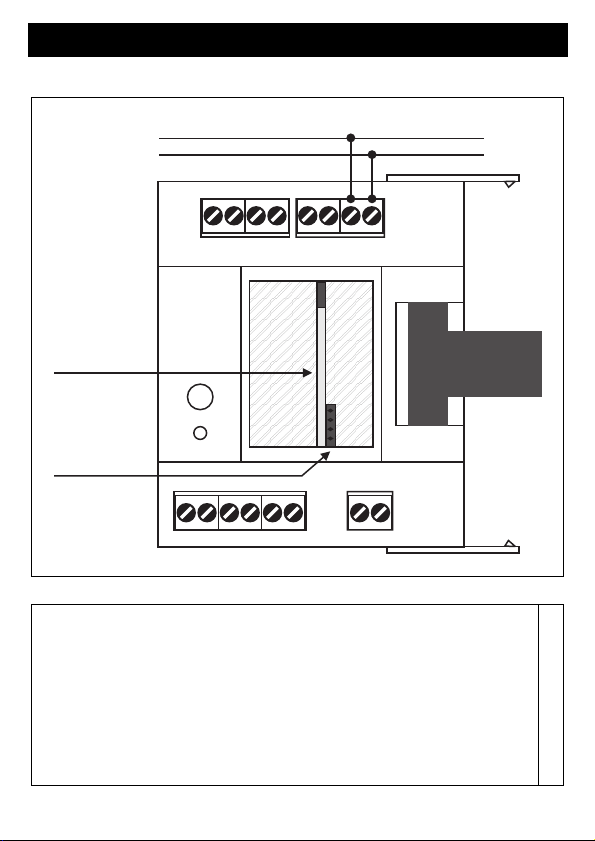
Mit dem Handkodiergerät DHK 1 kann über die 4-polige Stiftleiste an der Oberseite der
Platine jedem Kanal eine beliebige Adresse zwischen A1 und P8 zugeordnet werden.
Beim Verbinden des Programmierkabels ist darauf zu achten, dass dessen Punktmar-
kierung von der Platine abgewandt ist.
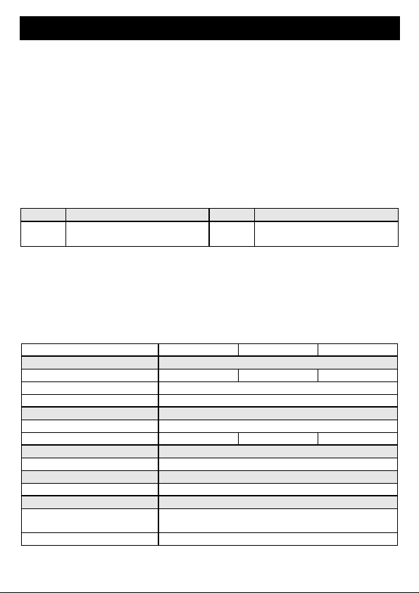
Die Aufteilung der Kanäle ist wie folgt:
Mit den Kanälen 1 bis 3 können die entsprechenden Schaltvorgänge ausgelöst werden;
die Kanäle 5 bis 7 reflektieren den aktuellen Zustand des am DFA angeschlossenen FI
oder LS. Kanal 8 meldet den Anzeigezustand der Betriebs-LED des DFA zurück.
Funktionen, die nicht benötigt werden, sollten unkodiert bleiben. Die Kodierung des
DFA-DI kann ohne Versorgungsspannung sowie ohne Dupline-Signal vorgenommen
werden. Sie bleibt dauerhaft erhalten, kann aber jederzeit überschrieben werden.
3. Montage
Die Installation darf nur von einer autorisierten Fachkraft vorgenommen werden.
ACHTUNG!
Beim DFA-DI handelt es sich um eine offene, ungeschützte Leiterplatte. Statische La-
dungen des Körpers können beim Berühren des DFA-DI dessen Bauteile zerstören.
Führen Sie deshalb vor dem Einbau eine Entladung durch, indem Sie geerdete Gegen-
stände mit der Hand berühren.
Kanal Beschreibung Kanal Beschreibung
1 FI/LS einschalten 5 Schaltzust. FI/LS: Eingeschaltet
2 FI/LS ausschalten 6 Schaltzust. FI/LS: Ausgeschaltet
3 FI auslösen 7 Schaltzust. FI/LS: Ausgelöst
4 Nicht belegt 8 Anzeige DFA Betriebs-LED

4 3931200/02/05/C
Doepke
Zudem ist vor der Montage der Platine der DFA und die zu schaltenden FI/LS von der
Betriebsspannung zu trennen. Zum Einbau ist zunächst der Deckel des DFA mithilfe ei-
nes Schraubendrehers zu öffnen. Im Gerät wird u.a. eine Buchsenleiste sichtbar, in die
das DFA-DI eingesteckt wird. Die vierpolige Stiftleiste muss dabei aus dem DFA heraus-
zeigen und in der Nähe der roten Klemme des DFA liegen; eine Verpolung ist jedoch
nicht möglich.
Sofern das DFA-DI noch nicht kodiert wurde, ist dieses vor dem Schließen des Gehäu-
sedeckels vorzunehmen.
4. Inbetriebnahme
Da die Verbindung zwischen der Platine und dem DFA bereits durch Aufstecken der Pla-
tine hergestellt wird, ist lediglich der Dupline-Bus an den DFA anzuschließen. Dies ge-
schieht an dessen Klemmen 7 (Dupline +) und 8 (Dupline -).
Folgende Tabelle zeigt die Anschlussbelegung:
5. Garantie
Für fachgerecht montierte, unveränderte Geräte gewähren wir ab Kauf durch den End-
verbraucher die gesetzliche Gewährleistungsfrist. Die Garantie bezieht sich nicht auf
Transportschäden sowie Schäden, die durch Kurzschluss oder Überlastung entstanden
sind. Bei Fertigungs- und Materialfehlern, die innerhalb der Gewährleistungsfrist erkannt
werden, leistet unser Werk kostenlosen Ersatz.
6. Technische Daten
Klemme Beschreibung Klemme Beschreibung
7 Dupline Signalleiter +
(Dupline +)
8 Dupline Signalleiter -
(Dupline -)
Min. Typ. Max.
Dupline
Stromaufnahme 320 µA 350 µA
Eingangskanäle 4 Statuskanäle
Ausgangskanäle 3 Steuerkanäle
Betriebsspannung
Nennbetriebsspannung Versorgung durch Fernantrieb DFA
Stromaufnahme 4,8 mA 5,5 mA
Anschlüsse
Siehe Anleitung Fernantrieb DFA
Gehäuse
Art Offene Leiterplatte
Allg. technische Daten
Schutzart / Normen Nach erfolgtem Einbau gelten die technischen Daten
des DFA.
Bestellnummer, -bezeichnung 09 100 102, DFA-DI

3931200/02/05/C 5
Doepke
7. Anschlussschema
8. Kontakt
Sollten Sie Fragen zu diesem Produkt oder zum Dupline-System haben, wen-
den Sie sich bitte an:
Doepke
Schaltgeräte GmbH & Co. KG
Stellmacherstraße 11
D-26506 Norden, Germany
Tel.: +49 (0) 4931/1806-0
Fax: +49 (0) 4931/1806-101
E-mail:
Internet:
http://www.doepke.de
3931200/02/05/C
Dupline +
Dupline -
Kodierstecker-
anschluss
Dupline-Platine
3931200_1A

6 3931200/02/05/C
Doepke
Operating Instructions
Dupline Remote Actuator DFA-DI
9. General Information
The Dupline DFA-DI interface is a component of the Dupline installation system and en-
ables the Doepke DFA remote actuator to be triggered via the Dupline bus. With the
DFA-DI all functions of the DFA can be called up via the Dupline bus and the switching
status be indicated. Operation, display and further processing can take place e.g. via PC-
based visualisation programmes, text or touch screen displays or via relay outputs.
The control signals transmitted via the Dupline bus have equal parity with any control
commands supplied via the signal inputs of the DFA.
The board is inserted directly into the DFA which also provides its power supply. Con-
nection to the Dupline bus is established via the terminals of the DFA.
Please observe the directions in the 3930131 operating and installation instructions
which are supplied with the DFA remote actuator.
10. Coding
With the DHK 1 hand encoder each channel can be assigned any address between A1
and P8 via the pin strip on the upper side of the board. When connecting the program-
ming cable ensure that its dot marking is facing away from the board.
The allocation of the channels is as follows:
With channels 1 to 3 the relevant switching operation can be triggered; channels 5 to 7
reflect the actual status of the RCCB or MCB connected to the DFA. Channel 8 is respon-
sible for the feedback of the indicator status of the DFA's control LED.
Functions which are not required should remain uncoded. The coding of the DFA-DI can
be carried out without either supply voltage or Dupline signal. It is retained permanently
but may be overwritten at any time.
11. Installation
The installation may only be carried out by an authorised trained technician.
CAUTION!
The DFA-DI is an open, unprotected circuit board. When touching the DFA-DI any static
charge of the body could damage the board's components. Therefore, before mounting
it discharge body static by touching earthed objects with your hands
Channel Description Channel Description
1Connecting RCCB/MCB 5RCCB/MCB switching status:
connected
2Disconnecting RCCB/MCB 6RCCB/MCB switching status:
disconnected
3Tripping RCCB/MCB 7RCCB/MCB switching status:
tripped
4Not assigned 8Display DFA control LED

3931200/02/05/C 7
Doepke
In addition, before mounting the board disconnect from the power supply both the DFA
and the RCCBs/MCBs to be switched. Preparatory to installation open the cover of the
DFA with a screwdriver. A socket terminal strip is then visible into which the DFA-DI has
to be plugged. The four-pole pin strip has to protrude from the DFA and should be located
near the red terminal of the DFA; however, a polarity mistake is impossible.
Before replacing the housing cover encode the DFA-DI if this has not already been car-
ried out.
12. Putting into Service
Because the connection between the board and the DFA has already been made by the
board's being plugged in, only the Dupline bus needs now to be connected to the DFA.
This is carried out at its terminals 7 (Dupline +) and 8 (Dupline -).
The following table illustrates the connection configuration:
13. Guarantee
All professionally installed, unaltered devices are covered by warranty during the statu-
tory guarantee period from the day of purchase by the end user. The guarantee is not ap-
plicable to damage incurred during transport or caused by short-circuit or overloading. In
the event of defects in workmanship or material, which are discovered within the guar-
antee period, the company will provide a replacement free of charge.
14. Technical Data
Pin Description Pin Description
7 Dupline signal conductor +
(Dupline +)
8 Dupline signal conductor -
(Dupline -)
Min. Typ. Max.
Dupline
Current input 320 µA 350 µA
Input channels 4 status channels
Output channels 3 control channels
Operating Voltage
Rated operating voltage Supply via DFA remote actuator
Current input 4.8 mA 5.5 mA
Terminals
Type Refer to instructions for DFA remote actuator
Housing
Type Open circuit board
General technical data
Encl. protection type /
standards
After installation the technical data of the DFA are ap-
plicable
Order number, description 09 100 102, DFA-DI

8 3931200/02/05/C
Doepke
15. Connection Diagram
16. Contact
In case of queries concerning this product or the Dupline system please contact:
Doepke
Schaltgeräte GmbH & Co. KG
Stellmacherstraße 11
D-26506 Norden, Germany
Tel.: +49 (0) 4931/1806-0
Fax: +49 (0) 4931/1806-101
E-mail:
Internet:
http://www.doepke.de
3931200/02/05/C
Dupline +
Dupline -
Coding plug
connection
Dupline
circuit board
3931200_1EA
Table of contents
Languages: