Dohrmann Enterprises DE-1000 User manual

REV 04.2011
D
Do
oh
hr
rm
ma
an
nn
n
A
Alic top
pp
plica
ator
rs
s
Owners Manual
for
D
Do
oh
hr
re
ec
ct
t
E
En
nj
je
ec
ct
t
S
Sy
ys
st
te
em
m
D
DE
E-
-1
10
00
00
0

2

3
WARRANTY
Dohrmann Enterprises, Inc. will replace or repair any applicator parts that are found to
be defective within 1 year from the original date of purchase with the exception of “wear
parts” (Pumping Tubes). Defective parts must be returned to Dohrmann Enterprises,
Inc. within 30 days of failure with shipping and handling fees prepaid.
NOTE: Failure to follow proper installation and maintenance instructions found in the
Owner’s Manual will VOID all warranty.
Defective parts caused by freight damage must be reported to the freight company by
the receiver.
NOTE: No warranty will be valid without the “Warranty Request Form” accompanied by
proof of purchase and the defective parts or equipment. See bottom of page for
“Warranty Request Form”.
This warranty shall not be interpreted to render Dohrmann Enterprises, Inc. liable for
injury or damages of any kind, direct consequential or contingent, to person or property.
Furthermore, this warranty does not extend to loss of crop, losses caused by delays or
any expense prospective profits or any other reason. Dohrmann Enterprises, Inc. shall
not be liable for any recovery greater in amount than the cost of repair of defects in
workmanship.
Dohrmann Enterprises, Inc. reserves the right to change parts as it deems necessary.
------------------------------------------------Cut here------------------------------------------------
Warranty Request Form
Customer Name___________________________ Phone__________________
Address _________________________________________________________
City __________________________ State __________ Zip Code ___________
Dealer Purchased From _____________________________________________
Model Number _______________________ Date of Purchase ______________
Serial Number ________________________
Note: Proof of purchase must accompany this form along with a letter stating the
problem with the defective part or equipment.
RETURN TO: Dohrmann Enterprises, Inc.
316 33rd Ave S
Waite Park, MN 56387

4

5
DE-1000
130
FM-1000 183
462
PA-1000
SP-2
156
182
364 451
130 – 10 Gallon Dohrect Enject Cooler Assembly
(Includes Valve & Fittings)
156 – Dohrect Enject Baseplate with Straps
182 – Dohrect Enject Discharge Bracket
183 – DE-1000 Flush Bottle Bracket
364 – 35’ DE-1000 Power Cord Assembly
364 Breakdown
364A – 15’ Power Cord (Power Supply to SP-2 Control)
364B – 20’ Power Cord (SP-2 Control to Pump)
451 – ¼” Clear Hose (X20)
462 – DE-1000 Flush Bottle Assembly
FM-1000 – DE-1000 Flowmeter Assembly
PA-1000 – DE-1000 Pump Assembly (No Hose or Power Cord)
SP-2 – DE-1000 Speed Control

DE-1000 Assembly & Installation Directions
Your Dohrect Enject Applicator requires minimal assembly. Your DE-1000 Applicator
comes in 2 separate assemblies.
1. Remove the tank and baseplate assembly from the box (Assembly 1).
2. Remove the cover and lift out the pump assembly (Assembly 2). This is the
black box with the power cord assembly and hoses attached.
3. Using the two 5/16” X 1” bolts provided, attach
the pump assembly to the baseplate (See
Figure 1). Be sure to mount the pump
assembly on the set of holes on the left of the
baseplate as shown in Figure 1. Connect the
input hose using the attached swivel nut to the
side output on the 3-Way Valve.
4. Remove the flush bottle assembly and slide
the flush bottle mount into the holder on the
right side of the tank. Connect the flush bottle
hose using the attached swivel nut to the top
input on the 3-Way Valve (see Figure 2).
Figure 1
Figure 2
5. Mount the frame assembly on a
flat surface that can be easily
accessed, we usually recommend
the right fender on self-propelled
choppers. For mounting a DE-
1000 on a pull-type chopper, use
the CM-2 Chopper Mounting Kit.
Follow the installation instructions
that are included with the CM-2
Chopper Mounting Kit.
6. The FM-1000 Flowmeter should
be mounted in a location that is
easy to view for the operator. Find
a desired location to mount the
FM-1000 Flowmeter and attach the flowmeter with the U-Bolt if mounting to a
railing. If mounting to a flat surface, use the self-tapping screws, or the ¼” nuts
and bolts provided. If using the self-tapping screws, drill a 3/16” hole. For most
accurate readings, the flowmeter needs to be mounted vertically. To make
adjustments assuring proper vertical installation you can loosen the bolts on the
swivel bracket, make the adjustments and then tighten the bolts.
6

DE-1000 Assembly & Installation Directions
7. Attach the discharge bracket so that the discharge tube will be mounted to apply
the product directly into the feed flow (knives and feed roll area). (See figure 3).
Flow Out
to
Discharge
FM-1000
Discharge
Bracket
Flow In
from
Pump
Figure 3
Figure 4
8. Run the discharge tube from the pump, past the flowmeter on the way to the
discharge bracket. Cut the hose at the flowmeter. Loosen the fittings on the
back of the flowmeter. The hose from the pump unit should be inserted into the
bottom flowmeter fitting and the hose to the discharge bracket should be
inserted into the top of the flowmeter, tighten the fittings to secure the hose, (See
Figure 4). Run the rest of the hose from the top of the flowmeter to the discharge
bracket.
9. Find a mounting location for the SP-2 Control Unit. It is recommended that this
be in a location which is within easy reach of the operator. Mount the controller
using the self-tapping screws; drill a 3/16” hole.
10.Connect the power cord to a 12 volt power supply. The RED lead should be
connected to positive (+) and the BLACK should be connected to negative (–).
We suggest taking power direct from the battery or from a 12 volt in-cab
connection. After everything is wired, if the control does not work, it has been
wired in reverse; change the red and black wires at the power source to correct
this problem.
NOTE: Be sure you have good, clean terminals and a good connection. This
system must be connected to a 12 volt system; 6 or 24 volts WILL NOT work.
11.Put water into the tank and run system to make any final adjustments.
7

8
System Troubleshooting
Problem: The red light on the SP-2 Control will not come on so the system will not
run.
Solution: 1. Unplug the control from the wiring harness and connect the wiring
harness together. If the pump does not run, either you do not have a
good connection or are wired to a switched power source and need to
turn on the switch.
2. Unplug the control from the wiring harness and connect the wiring
harness ends together. If the pump runs, but does not pump, check to
see if the pump is blowing bubbles back into the tank. If you see
bubbles in the tank, the system was wired incorrectly at the power
source. Switch the red and black wires around.
Problem: The system has worked for a while and does not pump any longer.
Solution: 1. Follow the instructions on pages 12 and 13 to replace the pumping
tube. Use the spare tube included in the manual bag. If replacing the
pumping tube, it is recommended to order a spare tube to have on
hand for the next replacement.
2. If you replaced the pumping tube and the pump still does not pump,
you may have to adjust the tension on the Pressure Yoke. For
instructions on how to do this, see page 13.

9
Operation & Calibration Instructions
1. When starting up your applicator for the first time, you may notice that after 15-
20 minutes of run time, the volume may increase; this is normal. During the first
15-20 minutes, your pumping tube is being broke in. Your system does not
need to go through a break in period before use. If you notice the volume
increase, simply use the SP-2 Control to adjust back to the desired rate.
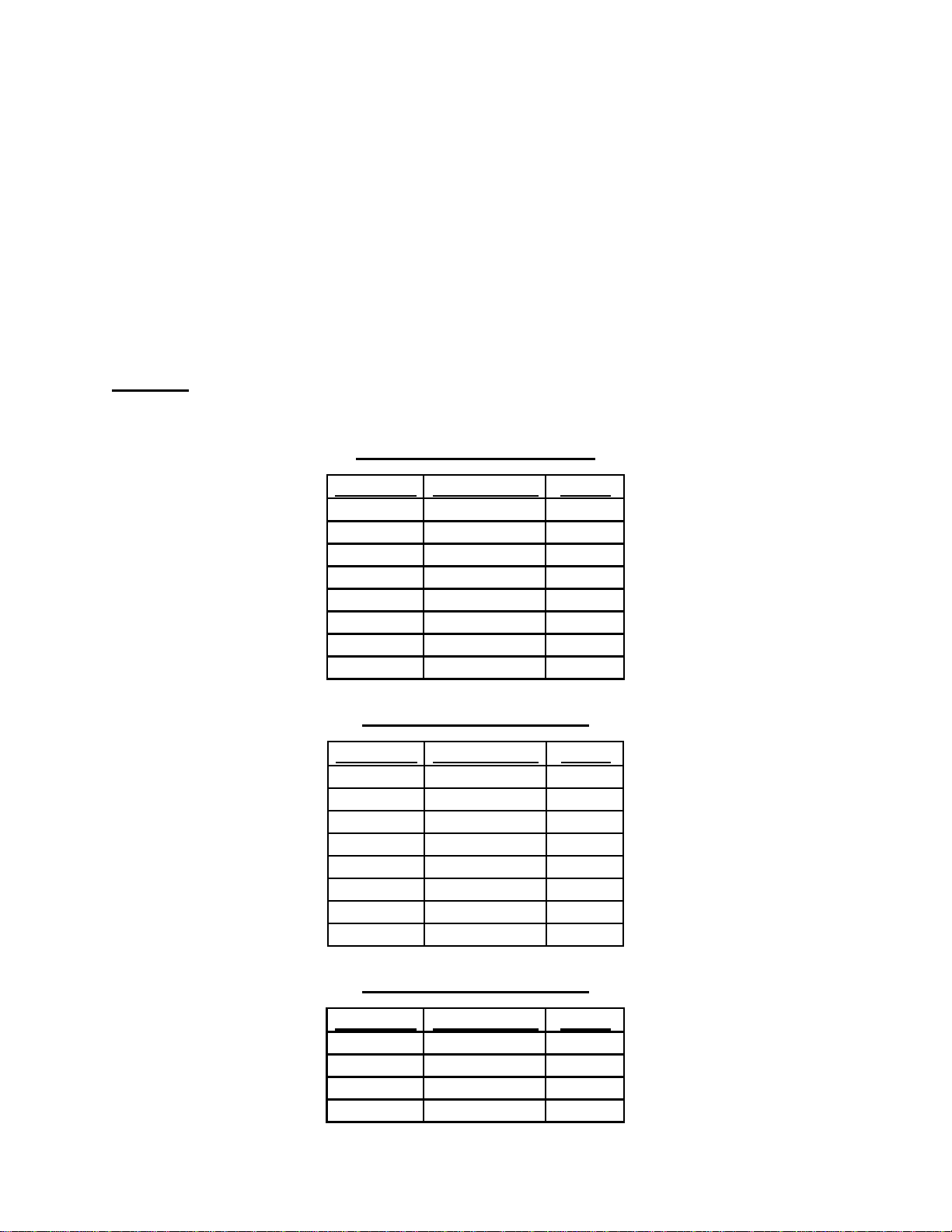
2. Calibrate your applicator against the charts found on pages 10 & 11. If you are
using your product mixed at the full concentrate rate of 100 tons per gallon,
simply float the ball on the line of the amount of tonnage you desire to treat per
minute. If you are using one of the other mix rates, refer to the chart on page 10
to find out the ounces per minute for your tonnage and float the ball on the line
for the desired ounces per minute found on the right side of the flowmeter.
3. Use the 2 quart mixing bottle for pre-mixing your product. Mix between 200-250
tons per mix. Mix the total amount of product you desire.
NOTE: The applicator is designed to mix up to 100 treatable ton of product per
gallon (see the calibration charts on the following page to find your desired
mixing rate based on your harvest rate).
Example 1: If you wish to mix for 400 treatable ton of product, you would mix 2
batches of 200 ton in the mixing jug. Then dump the solution into the tank. Fill
the tank up to 4 gallons. This mix will allow for an application rate of 1.28 oz/ton
(100 ton per gallon mix).
Example 2: If you wish to mix for 400 treatable ton of product, you would mix 2
batches of 200 ton in the mixing jug. Then dump the solution into the tank. Fill
the tank to 8 gallons. This mix will allow for an application rate of 2.56 oz/ton
(50 ton per gallon mix).
4. Add frozen plastic bottles (20 oz. soda bottle) of water to assist with providing a
cool environment for the product. At the days end, or during any prolonged
interruption of chopping (weather, breakdown, etc.), ice packs or frozen bottles
of water may be added to keep the product cool. (Ice packs or bottles not
included with the applicator.)
5. Your applicator should be flushed at the end of each day. To do this, turn the 3-
way valve handle up toward the flush bottle input. This will allow the pump to
draw clean water from the flush bottle and flush out the entire product line.
NOTE: 4 ft. of product line will contain enough product for 1 ton of forage. It is
recommended to flush out the product onto the last batch of forage harvested.
COLD WEATHER FLUSHING: During cold weather when there is a possibility
of the product lines freezing overnight, it is recommended to fill the flush bottle
with RV Waterline Antifreeze and flush the system. This will prevent the lines
and the flowmeter from freezing and cracking.
6. It is recommended to flush out the tank between batch mixes to remove any
product settlings. To do this, remove the tank and rotate the swivel connection
to expose the filter screen and rinse out with clean water. This will clean out the
tank and filter.

Calibration Charts
The Calibration Charts below are to provide you with the amount of total solution that
you need to apply based upon your mix rate and tonnage per minute harvested. Please
note that you may need to change your mix rate if your harvest rate drops below the
lowest output of the pump.
These charts are to be used along with the FM-1000 Flowmeter Assembly for
calibration of your system. For pull-type choppers, you may not be able to have your
flowmeter in easy view. In this case, you can find your desired output using the
flowmeter and mark the dial setting of the SP-2 Control in the Dial Number location.
To find out how much tonnage per minute you are harvesting, use the example found
below.
Example: If you are filling a 12-ton wagon/truck in 4 minutes = 3 tons per minute. To
find this out, take the forage weight and divide by the time in minutes to chop.
100 Ton Per Gallon Mix
Tons/Min Ounces/Min Dial #
1.50 1.92
2.00 2.56
2.50 3.20
3.00 3.84
3.50 4.48
4.00 5.12
4.50 5.76
5.00 6.40
50 Ton Per Gallon Mix
Tons/Min Ounces/Min Dial #
0.75 1.92
1.00 2.56
1.25 3.20
1.50 3.84
1.75 4.48
2.00 5.12
2.25 5.76
2.50 6.40
25 Ton Per Gallon Mix
Tons/Min Ounces/Min Dial #
0.50 2.56
0.75 3.84
1.00 5.12
1.25 6.40
10

11

Service & Maintenance
The DE-100 Applicator has only one “wear part”. This part is the Pumping Tube. The
Pumping Tube needs to be replaced when it wears out (approximately 700-1,000 hours)
or at the beginning of every year, whichever comes first. If the Pumping Tube wears
out, the motor will still run, but it will not pump any product.
Replacing the Pumping Tube
(See Figures 5 & 6)
1. Remove the Connector Locking Bar by loosening the screw. Then allow the
Connector Locking Bar to slide down over the hoses.
2. Access the pump by removing the 4 plate screws on the bottom of the pump
base.
3. Disconnect the Inlet and Outlet Tubing by turning the hose connections (Box
Fittings) on the pump inlet and outlet a ¼ turn counter clockwise.
4. Tip the Yoke Adjustment Screw to the right. Lift the Pressure Yoke up to
expose the Pumping Tube.
5. The Pumping Tube can now be replaced by reversing the procedure.
NOTE: Be sure that the Pumping Tube is stretched evenly over the roller.
12
Figure 5
106 – DE-1000 Pump
460 – DE-1000 Pumping Tube
463B – DE-1000 Housing Baseplate
464 – Connector Locking Bars (1 Set, 2 Pieces)
465 – Female Luer X ¼” HB Fitting – “Box Fitting”
106
460
463B 465
464

Replacing the Pumping Tube (Continued)
(See Figures 5 & 6)
NOTE: The Yoke Adjustment Screw may at some time need attention. This screw sets
the pressure the Pressure Yoke applies to the Pumping Tube. If this ever needs to be
done, use the small Hex Head Wrench provided to loosen the set screw (See Figure 6).
This is set at the manufacturer and should not need to be changed.
Yoke
Adjustment
Screw
Pressure
Yoke
Set
Screw
Figure 6
13

14
130/GSK
302
234-3926
456
Cooler
Wall
Inside Cooler CVA-1000
331 449
333
301
332
CVA-1000 Breakdown
301 – ¼” Gauge Elbow
331 – ¼” MPT X Nozzle Body Close Nipple
332 – ¼” X ¼” FPT Coupler
333 – ¼” X ¼” Close Nipple
449 – ¼” 3 Way Valve
Not Included as part of the CVA-1000
130/GSK – Cooler Gasket
234-3926 - ½” FPT X ½” Swivel Elbow
302 – ½” X ¼” Reducer Bushing
456 – ¼” Suction Strainer
Table of contents