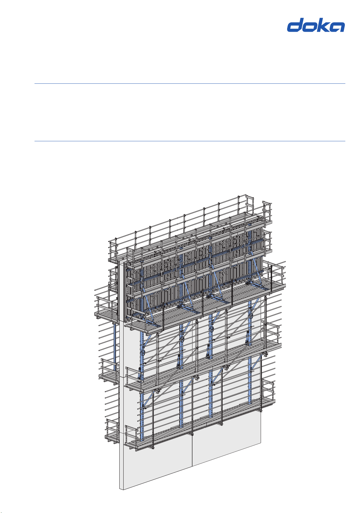
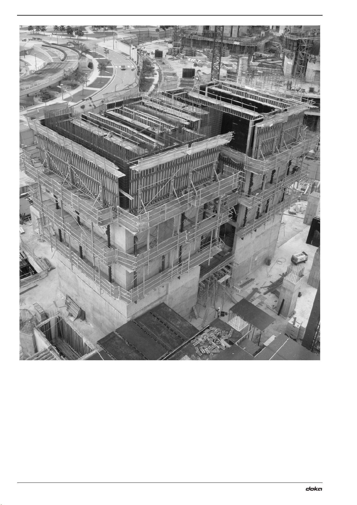
User Information Automatic climbing formwork Xclimb 60 Introduction
5999801002 - 02/2017
Rules applying during all phases of
the assignment
▪The customer must ensure that this product is
erected and dismantled, reset and generally used for
its intended purpose in accordance with the applica-
ble laws, standards and rules, under the direction
and supervision of suitably skilled persons.
These persons' mental and physical capacity must
not in any way be impaired by alcohol, medicines or
drugs.
▪Doka products are technical working appliances
which are intended for industrial / commercial use
only, always in accordance with the respective Doka
User Information booklets or other technical docu-
mentation authored by Doka.
▪The stability of all components and units must be
ensured during all phases of the construction work!
▪The functional / technical instructions, safety warn-
ings and loading data must all be strictly observed
and complied with. Failure to do so can cause acci-
dents and severe (even life-threatening) damage to
health, as well as very great material damage.
▪Fire-sources are not permitted anywhere near the
formwork. Heating appliances are only allowed if
properly and expertly used, and set up a safe dis-
tance away from the formwork.
▪The work must take account of the weather condi-
tions (e.g. risk of slippage). In extreme weather,
steps must be taken in good time to safeguard the
equipment, and the immediate vicinity of the equip-
ment, and to protect employees.
▪All connections must be checked at regular intervals
to ensure that they are secure and in full working
order.
In particular threaded connections and wedged con-
nections have to be checked and retightened as nec-
essary in accordance with activity on the jobsite and
especially after out-of-the-ordinary occurrences (e.g.
after a storm).
▪It is strictly forbidden to weld Doka products – in par-
ticular anchoring/tying components, suspension
components, connector components and castings
etc. – or otherwise subject them to heating.
Welding causes serious change in the microstruc-
ture of the materials from which these components
are made. This leads to a dramatic drop in the failure
load, representing a very great risk to safety.
The only articles which are allowed to be welded are
those for which the Doka literature expressly points
out that welding is permitted.
Assembly
▪The equipment/system must be inspected by the
customer before use, to ensure that it is in suitable
condition. Steps must be taken to rule out the use of
any components that are damaged, deformed, or
weakened due to wear, corrosion or rot.
▪Combining our formwork systems with those of other
manufacturers could be dangerous, risking damage
to both health and property. If you intend to combine
different systems, please contact Doka for advice
first.
▪The equipment/system must be assembled and
erected in accordance with the applicable laws,
Standards and rules by suitably skilled personnel of
the customer's, having regard to any and all required
safety inspections.
▪It is not permitted to modify Doka products; any such
modifications constitute a safety risk.
Closing the formwork
▪Doka products and systems must be set up so that
all loads acting upon them are safely transferred!
Pouring
▪Do not exceed the permitted fresh-concrete pres-
sures. Over-high pouring rates overload the form-
work, cause greater deflection and risk breakage.
Stripping out the formwork
▪Do not strip out the formwork until the concrete has
reached sufficient strength and the person in charge
has given the order for the formwork to be stripped
out!
▪When stripping out the formwork, never use the
crane to break concrete cohesion. Use suitable tools
such as timber wedges, special pry-bars or system
features such as Framax stripping corners.
▪When stripping out the formwork, do not endanger
the stability of any part of the structure, or of any
scaffolding, platforms or formwork that is still in
place!