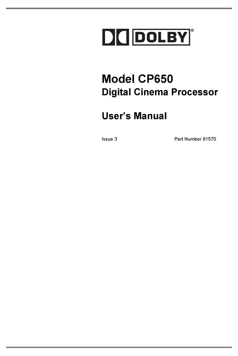
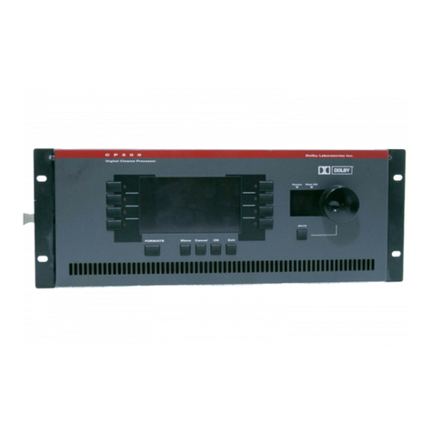
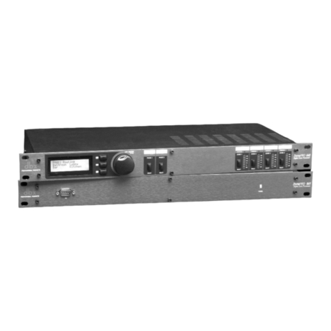
Dolby Laboratories CP650 User manual

Model CP650
Digital Cinema Sound
Processor
User’s Manual
Issue 1 Part No. 91570

CP650 User’s Manual
ii
Dolby Laboratories Inc
Corporate Headquarters
Dolby Laboratories Inc
100 Potrero Avenue
San Francisco, CA 94103-4813
Telephone 415-558-0200
Facsimile 415-863-1373
www.dolby.com
European Headquarters
Dolby Laboratories
Wootton Bassett
Wiltshire, SN4 8QJ, England
Telephone (44) 1793-842100
Facsimile (44) 1793-842101
WARNING: To avoid the risk of electrical shock or fire, do not attempt to service
the CP650 or remove the front panel. Do not remove the power supply housing
located on the rear of the Digital Soundhead. Refer all service and repairs to
qualified technicians. This apparatus shall not be exposed to dripping or splashing
and no objects filled with liquids shall be placed on the apparatus.
The CP650 was installed and adjusted initially by a trained engineer so that your theatre would have the same
standard playback characteristics as the dubbing theatres in which all Dolby films are mixed. This results in the most
accurate sound reproduction possible. Do not attempt to adjust any controls within the CP650 except those
specified in this manual. Adjusting internal controls requires the use of special test equipment. Tampering with
these controls can have an adverse effect on the sound in your theatre and will require a service call to restore proper
operation. The first thing to do when you have a problem is to read Section 4 Troubleshooting.
In addition, do not adjust any of the controls on the other audio equipment in your theatre sound system, such as
power amplifiers. They have been preset by the installer. For example, misadjusting the power amplifier gain
controls can cause channel imbalance and/or too much power amplifier noise. Those controls have been set by the
installer for correct channel balance. The film play level should be correct in the theatre with the front panel fader
reading 7.0.
DISCLAIMER OF WARRANTIES: Equipment manufactured by Dolby Laboratories is warranted against defects
in materials and workmanship for a period of one year from the date of purchase. All warranties, conditions, or other
terms implied by statute are excluded to the fullest extent allowed by law.
LIMITATION OF LIABILITY: It is understood and agreed that Dolby Laboratories’ liability whether in contract,
in tort, under any warranty, in negligence or otherwise shall not exceed the cost of repair or replacement of the
defective components and under no circumstances shall Dolby Laboratories be liable for incidental, special, direct,
indirect, or consequential damages (including but not limited to damage to software or recorded audio or visual
material), or loss of use, revenue, or profit, even if Dolby Laboratories or its agents have been advised, orally or in
writing, of the possibility of such damages.
Dolby, Surround EX, AC-3, and the double-D symbol are trademarks of Dolby Laboratories.
2000 Dolby Laboratories Inc; all rights reserved.
Issue 1
S00/13072
Part No. 91570
CP650 User’s Manual
iii
Table of Contents
Chapter 1 Introduction 1-1
1.1 About the CP650 ......................................................................................1-1
1.2 About This Manual...................................................................................1-1
Chapter 2 Operating Instructions 2-1
2.1 The CP650 Front Panel.............................................................................2-1
2.2 Normal Operation .....................................................................................2-4
2.2.1 Power On.....................................................................................2-4
2.2.2 Format Selection .........................................................................2-5
2.2.3 Main Fader ..................................................................................2-6
2.2.4 Setup for Automatic Selection of the Dolby Digital Format ......2-7
2.2.5 Assigning Formats to the U1, U2 and NS Buttons .....................2-8
2.2.6 The Mute Function......................................................................2-9
2.2.7 Setting the Front Panel Display Contrast..................................2-10
2.2.8 Operation With an Automation System ....................................2-10
2.3 Bypass Operation....................................................................................2-11
Chapter 3 Maintenance and Adjustments
3.1 Soundhead Maintenance...........................................................................3-1
3.1.1 Analog Sound System.................................................................3-1
3.1.2 Digital Sound System..................................................................3-1
3.1.3 Replacing the Exciter Lamp (Cat. No. 700)................................3-2
3.2 Dolby Level Calibration ...........................................................................3-3
3.3 Film Print Cleanliness ..............................................................................3-4
Chapter 4 Troubleshooting
4.1 If Film Sound Is Lost................................................................................4-1
4.2 If One Channel Fails or is Distorted.........................................................4-1
4.3 If Switching to Bypass Does Not Restore Sound.....................................4-2
4.4 If You Hear Extraneous Noises When Playing a Digital Film.................4-2
4.5 Excessive or Inappropriate Sound From Surround Speakers ...................4-2
4.6 Troubleshooting Chart..............................................................................4-2
Appendix A How to Identify Sound Tracks on Prints
Appendix B Advanced Operations
B.1 Display The Event Log............................................................................B-1
B.2 Display Information About This CP650 Unit .........................................B-2
Appendix C Test and Demonstration Films
Appendix D The Evolution of Dolby Film Sound
Appendix E Reference Information
List of Cat. Numbers Used
Appendix F CP650 Menu Listing


CP650 User’s Manual
1-1
Chapter 1
Introduction
1.1 About the CP650
The Dolby CP650 Digital Cinema Sound Processor is the heart of your theatre sound
system. All sound sources are connected to the CP650, which processes the signals
appropriately and feeds them to the power amplifiers. Entirely self-contained, the
CP650 provides both Dolby Digital and Dolby analog processing. An easy-to-read
front panel screen and uncomplicated front-panel buttons make it easy to operate.
Software that can be readily programmed controls all existing film sound formats.
Calibration settings for a given theatre can be stored on a PC and, should the need
arise, they can be transferred directly to another CP650, thereby reducing or
eliminating the need for recalibration after repairs. As improvements to the CP650
digital control and processing software are developed, the latest revisions can be
downloaded from a PC to the CP650 hardware. Moreover, updates to the audio
coding used for Dolby Digital soundtracks, which are included from time to time
right on Dolby Digital release prints, download automatically into the CP650 the first
time such a print is played in the cinema.
1.2 About This Manual
This user’s manual has been prepared specifically to help projectionists get the most
from the Model CP650 and the theatre sound system once it has been installed and
aligned. (Installation and alignment instructions are supplied to the local distributor or
installation company.) We suggest that you keep this manual readily available.
The manual is organized as follows:
•Chapter 1, Introduction, this chapter.
•Chapter 2, Operating Instructions, covers the basic control functions and
operation of the CP650.
•Chapter 3, Maintenance and Adjustments, contains tips for maintaining the
CP650 and the theatre sound system.
•Chapter 4, Troubleshooting, will help you track down problems in the sound
system without test equipment. It consists of a troubleshooting chart and
procedures to follow during a show, between shows, and after closing.
•The Appendices contain valuable background information to help you get the
most out of the Model CP650 and your theatre sound system.


CP650 User’s Manual
2-1
Chapter 2
Operating Instructions
2.1 The CP650 Front Panel
menu mute
7.0
P1 P2
Format Buttons
Used to select the sound format:
01 Mono
04 Dolby A-Type
05 Dolby SR
10 Dolby Digital
11 External Six Channel Input
U1 User-defined during setup
U2 User-defined during setup
NS Normally Format 60
Non-sync 1,
(can be User-defined)
Level Display
Displays fader setting. Ranges from
0.0 to 10. Normally set to read 7.0.
Projector Signal Indicators
P1 and P2 show which projector's
output is being processed by the
CP650.
Bypass Power Supply
Failure Indicator
Indicates a problem detected in the bypass
power supply.
Front Panel Display
Displays current format and processor
condition.
Setup Panel Access Door
For use by the service engineer.
Power Button
Operates the main power supply. When switched
to the position, the CP650 is powered by the
main supply. If a fault in the main power supply is
detected the button glows red and the unit
automatically switches to bypass operation. When
switched to the position, the unit is powered
by the built-in bypass power supply and the button
also glows red.
ON
OFF
Main Fader Knob
Controls sound level and is used for
menu operations during setup.
OK Button
Stores the displayed
setting in the
CP650 memory.
Mute Button
Fades down and fades up the signal
to all channels without disturbing the
current main fader setting. Flashes
red when activated to fade down.
Pressing a format button will cancel
mute.
Select Button
Selects a parameter to change.
The change is made by rotating
the main fader knob.
Next Menu Button
Steps through the
menu list.
Figure 2-1 CP650 Front Panel
Front Panel Display
Day-to-day operation of the CP650 is performed through interaction with this display.

CP650 User’s Manual Operating Instructions
2-2
L C R Ls Rs Sw
The example above shows the normal display when the CP650 is playing a film with
a Dolby Digital soundtrack. The top two lines display the current format selected. The
bottom left area contains a bar graph display of the sound signals present on each
channel. As the film plays, the bars will move, confirming that sound is passing
through the CP650.
M1 indicates that the projector 1 motor contact is closed (in two-projector
installations). In single-projector installations it will always show as M1. The motor
start signal is used during projector changeovers on Dolby Digital films in two-
projector installations.
The 0shown on the bottom right displays the Dolby Digital film error rate. The first
indication of satisfactory digital film playback is by detecting a low error rate. The
error rate is a number between 0 and 8. With a correctly aligned digital film reader,
most films will play at an error rate of 6or lower. If the digital error rate exceeds 8, or
if the display shows “F” (data not readable) or “–”(no digital soundtrack), the CP650
will automatically switch to playing the film’s analog soundtrack until usable data
appears.
Level Display
The main fader level is displayed as a two-digit number. Starting from a display of
0.0,the level increases as the fader knob is rotated clockwise. As with previous
generations of Dolby cinema processors, a fader setting of 7.0
7.07.0
7.0 is the correct operating
level. This setting matches the level used during production of the film.
Main Fader Knob
Use this knob to adjust the sound level. As the main fader is turned, the numbers on
the display will move from 0.0
0.00.0
0.0 to 10
1010
10. A fader reading of 7.0
7.07.0
7.0 is the correct operating
level. The main fader knob rotates continuously with no end-stops. The knob is also
used to choose various menu items during setup operations.
Projector Signal Indicators
P1 and P2 show which projector analog optical sound input has been selected by the
CP650.
Bypass Power Supply Failure Indicator
This indicator turns on if a problem is detected in the bypass power supply circuitry.

CP650 User’s Manual Operating Instructions
2-3
Power button
The power button operates the main power supply for the CP650. In the ON position,
the CP650 is powered by the main supply. As with other Dolby cinema processors,
the CP650 has a separate backup (bypass) power supply. In the OFF position, the unit
is powered by the built-in bypass power supply, and the power button glows red. It
also glows red if a fault is detected during normal operation (power button in the ON
position), indicating that the unit has automatically switched to bypass operation.
Format Buttons
Used to select the desired film sound format:
01 Mono
04 Dolby A-type
05 Dolby SR
10 Dolby Digital
11 External six-channel signal
U1, U2 Set by the user. See instructions later in this chapter.
NS Nonsync, for intermission music tape, CD player, and so on. Usually Format 60
and can be set to other formats.
Setup Control Panel Access Door
For use only by the service or installation engineer.
Mute Button
Press the mute button to fade down the sound on all channels without disturbing the
current fader setting. The speed of fade-in/fade-out is adjustable from 0.2 sec to 5 sec.
The button flashes red when mute is activated.
Menu Control Buttons
Use the menu control buttons to navigate through the various menus displayed on the
front panel screen, select various menu options, and store setup data.
menu
OK
Figure 3-2 CP650 Setup Menu Control Buttons
Use the left-hand next menu button to step through the menu list. Press and release the
button once to change the display to the next menu item. Press and hold the button
while rotating the main fader knob to step the display through all menu items.
Use the center select parameter button to select a parameter to adjust when there are
multiple items available on the display. Press and release the button to select among
them. Then, to make the adjustment, rotate the main fader knob.

CP650 User’s Manual Operating Instructions
2-4
Use the right-hand OK button to accept the setting displayed on the front panel
screen and store it in CP650 memory. Any changes to settings will occur
immediately but will not be saved until this button is pressed. Leaving the current
menu before pressing the OK button will cause the change to be discarded.
Note: For convenience, pressing the current format (glowing) button causes the
CP650 to immediately return to the top-level screen display. This feature is handy for
making a quick change, then returning to normal operation.
2.2 Normal Operation
2.2.1 Power On
During the CP650 installation, the power-on state of the unit was configured from the
following choices. Each time the CP650 is connected to power, it automatically sets
itself to the selected “wake-up” state:
•Projector 1or 2selected by the installation technician.
•If the front-panel fader is selected, the system will start up at the last fader
setting before power was turned off. If the auditorium fader was selected, the
system will read the setting of the auditorium fader knob.
•The film sound format which was active when power was turned off, or the
film sound format previously stored as the “power-on” format. (The format
options can be set using the procedure described later in this chapter.)
If power has been removed for longer than approximately three weeks, the CP650
wake-up state is:
•Front-panel main fader activated and set to 7.0
7.07.0
7.0.
•Format 10, Dolby Digital.
•Power-on format is set to Last Format used before power was turned off.

CP650 User’s Manual Operating Instructions
2-5
CP650
Loading.........
........
Built: XXXyy Time
R
unn
i
ng se
lf
t
es
t
Checking xxxxxxxx
Checking yyyyyyyy
Checking zzzzzzzz
When power is first applied, the first screen shows
that the software is loading into CP650 memory, and
displays the software date.
Next, a brief self-test of various internal circuitry is
automatically started.
Finally, the normal operating screen appears. Details
on the items displayed are described earlier in this
chapter. This is the only screen you will need to see
for ordinary operation.
2.2.2 Format Selection
Select the desired film soundtrack format or your nonsync source by pressing the
appropriate front-panel button. The button illuminates and the format number appears
on the screen to confirm that the format was selected. Common formats are:
01 Mono: for all optical prints of any vintage with conventional mono optical
(“Academy”) soundtracks.
04 Dolby A-type: for Dolby releases, except those marked SR or Digital.
05 Dolby SR: for releases marked as having a Dolby SR (Spectral Recording)
soundtrack or for Dolby Digital prints if your CP650 is not equipped with digital
playback capability.
10 Dolby Digital: for Dolby Digital film releases. The digital data is clearly
visible between the film perforations next to the analog soundtrack. (Your CP650
must be equipped with a Cat. No. 773 board.)
11 External 6ch: for selecting an external six-channel analog sound source.
NS nonsync: Usually Format 60. For playing an intermission music tape or CD.
The film-soundtrack format numbers used on the CP650 buttons (and also on models
CP45, CP65, and CP500 often appear on the film can and leader. If these numbers are
not supplied and you are not sure if a print is mono, stereo optical, or digital, see
Appendix A which explains how to identify the various types of soundtracks.

CP650 User’s Manual Operating Instructions
2-6
F
a
d
er
S
e
tti
ng
Auditorium
Saving Changes...
2.2.3 Main Fader
The main front panel fader knob on the CP650 controls the volume level in the
theatre. It works in both normal and bypass operation. When the CP650 has been
correctly installed, setting the fader to 7.0
7.07.0
7.0 plays the film at the level at which it was
mixed. This is the proper level for any Dolby encoded film.
Although a minor adjustment in playback level might be required under unusual
circumstances, avoid significant deviations from the correct level 7.0
7.07.0
7.0 established by
the installer. If the playback level is set too low, dialogue may be hard to understand;
too high a level may cause complaints from the audience, and under extreme
circumstances, can damage the theatre’s sound system.
Auditorium Fader
If an analog (not a Dolby Cat. No. 779 Digital Remote Unit or Cat. No. 771 Remote
Fader) auditorium fader has been installed, it is activated by performing the following
menu steps:
menu
OK
Press the left menu button to step the menu to Fader
Setting.
Note: you can also press and hold the left menu button while
rotating the front-panel fader knob clockwise to step through the
menu items.
Rotate the fader knob to select Auditorium.
OK
Press the OK button to save the change.
Note: When auditorium fader is selected, the CP650 front-
panel main fader and any Cat. No. 779 or Cat. No. 771 remote
faders installed in your system will be disabled. Only the analog
auditorium fader pot will be active.
Press the illuminated format button to return to
normal operation.
To return control back to the main fader and/or digital remote faders, repeat the above
steps and select Local on the fader setting menu.

CP650 User’s Manual Operating Instructions
2-7
A
u
t
o
D
o
lb
y
Di
g
it
a
l
>Disabled
Saving Changes...
A
u
t
o
D
o
lb
y
Di
g
it
a
l
>Enabled
2.2.4 Setup for Automatic Selection of the Dolby Digital Format
CP650 units equipped to play Dolby Digital films can be set up to sense the presence
of Dolby Digital data on the film and automatically switch the CP650 to the Dolby
Digital format from any other film format. In other words, if the CP650 is operating
in Format 01, 04, 05, or 11, it will automatically switch to Format 10 when a Dolby
Digital film is detected. CP650s are shipped from the factory with this feature
enabled.
To enable the auto-digital feature:
menu
OK
Press the left menu button.
The Auto Dolby Digital select screen will appear.
Rotate the front-panel fader knob to display enabled.
menu
OK
Press the OK button to save the change.
Press the illuminated format button to return to
normal operation.

CP650 User’s Manual Operating Instructions
2-8
Saving Changes...
U
ser
F
orma
t
1
>
>>
>Format 13
Surround EX
U
ser
F
orma
t
2
>
>>
>Format 65
Public Address LsRs
Saving Changes...
N
onsync
F
orma
t
>
>>
>Format 60
Nonsync 1
Saving Changes...
2.2.5 Assigning Formats to the U1, U2 and NS Buttons
The U1 and U2 buttons (User Format 1 and User Format 2) and the NS button
(nonsync) can be assigned to any available format. Then, when the button is pressed,
the assigned format will be selected.
menu
OK
Press the left menu button multiple times to step
through the menus to User Format 1.
Note: you can also press and hold the left menu button while
rotating the front-panel fader knob clockwise to step through the
menu items.
Rotate the fader knob to select one of the many
format choices available. This example shows
Format 13, Dolby Digital Surround EX, selected.
OK
Press the OK button to save the assignment to the
User 1 button.
1x
Press the left menu button once to step to the User
Format 2 menu.
Rotate the fader knob to select the desired format.
This example shows Format 65, PA microphone
sent to left and right surround speakers.
OK
Press the OK button to save the assignment to the
User 2 button..
1x
Press the left menu button once to step to the
Nonsync Format menu.
Rotate the fader knob to select the desired format to
be selected when the NS button pressed. This
example shows Format 60, the Nonsync 1 rear panel
input.
OK
Press the OK button to save the assignment to the NS
button.
Press the illuminated format button to return to
normal operation.

CP650 User’s Manual Operating Instructions
2-9
M
u
t
e
F
a
d
e-
i
n
Ti
me
>x.x Seconds
Saving Changes...
M
u
t
e
F
a
d
e-ou
t
Ti
me
>x.x Seconds
2.2.6 The Mute Function
Use the mute function between intermission music and starting the projector to
prevent the audience from hearing annoying thumps and leader crackle at the
beginning of the show. It is also useful if the film breaks or runs out while the
projector is active, since it suppresses the very loud signal that occurs when leaders or
tails pass through the projector.
When you press the mute button, the volume will automatically fade all the way
down on all channels. The button will flash, indicating that the CP650 outputs are
muted. When you press the button again, or select a new format, the volume will
automatically rise to the level set by the fader.
The fade-out and fade-in time can be set to work from 0.2 to 5 seconds by following
this procedure:
Mute Fade Time
menu
OK
Press the left menu button multiple times to step
through the menu items to Mute Fade-in Time.
Note: you can also press and hold the left menu button while
rotating the front-panel fader knob clockwise to step through the
menu items.
Rotate the knob to select the desired time for the
sound to fade-in. The time is adjustable from 0.2 to
5.0 seconds.
OK
Press the OK button to save the change.
1x
Press the left menu button once to step the menu to
Mute Fade-out Time.
Rotate the fader knob to select the desired time for
the sound to fade-in. The time is adjustable from 0.2
to 5.0 seconds.

CP650 User’s Manual Operating Instructions
2-10
Saving Changes...
C
on
t
ras
t
Adj
us
t
men
t
> 10
Saving Changes...
OK
Press the OK button to save the change.
Press the illuminated format button to return to
normal operation.
2.2.7 Setting the Front Panel Display Contrast
The liquid crystal display (LCD) contrast can be adjusted to give the clearest possible
readability.
menu
OK
Press the left menu button multiple times to step
through the menu items to Contrast Adjustment.
Note: you can also press and hold the left menu button while
rotating the front-panel fader knob clockwise to step through the
menu items.
Rotate the fader knob while watching the display.
Adjust for the most pleasing appearance. This
example shows the contrast set to “10”.
OK
Press the OK button to save the change.
Press the illuminated format button to return to
normal operation.
2.2.8 Operation With an Automation System
When the CP650 in your theatre is connected to automation equipment, the format
selection is duplicated elsewhere. In most cases, the front-panel buttons of the CP650
can usually be used to override commands from the automation system; however, as
automation equipment differs from installation to installation, check with the installer
of your system if you have any questions about its operation and whether you can
easily override the automation commands.

CP650 User’s Manual Operating Instructions
2-11
2.3 Bypass Operation
The CP650 has an independent power supply for emergency operation. If the main
power supply or processor circuitry fails, the unit will automatically switch to bypass
operation, allowing the show to continue with limited sound processing functions.
Bypass operation is indicated by the front-panel power button glowing red.
In the case of other problems, such as distortion or the loss of a channel, the bypass
mode can be selected manually by pressing the power button.
There are other components in the theatre sound system that could also fail. Be sure
to refer to Chapter 4, Troubleshooting, any time there is a problem.
The following occurs when the CP650 is operating in the bypass mode:
•The power button glows red and the display screen is off.
•Only the front-panel main fader operates; no other remote fader works.
•All other front-panel buttons do not work.
•The optical preamp circuit of the selected projector remains operational and is
fed to the CP650 left, center, and right channel outputs.
•Even when a stereo print is playing, a mono signal is fed to all screen
speakers. Thus, you can switch to the bypass mode to keep the show going if
one of the power amplifiers fails.
•All Dolby processors, speaker equalizers, and subwoofer circuits are switched
out of the signal path.
Be sure to follow the troubleshooting procedures and, if necessary, call your service
engineer as soon as possible.
Note: The CP650 will not operate, even in the bypass mode, if there is a fault in any of the following areas:
•The AC mains power to the CP650.
•Bypass power supply fuse or bypass power supply circuit.
•The optical preamplifier circuitry or bypass circuitry on the Cat. No. 772 board.
It is strongly recommended that a spare Cat. No. 772 board be kept on hand for substitution in emergencies.
If the front-panel bypass power supply failure indicator (located directly above the
main fader knob) is on, the CP650 will not operate in bypass mode.


CP650 User’s Manual
3-1
Chapter 3
Maintenance and Adjustments
Having the very best equipment in your installation does not in itself guarantee that
you will always achieve best results. A number of routine maintenance and
adjustment procedures, requiring no special test equipment or technical knowledge,
are necessary to realize the full potential of the sound system on a day-to-day basis.
These procedures can also prevent costly show cancellations and service calls.
A Dolby Cat. No. 69T test film is required for proper maintenance of your sound
system. We also recommend that you keep on hand the Dolby Cat. No. 251 Jiffy Test
Film and run it regularly to check the theatre sound system thoroughly (see
Appendix C).
3.1 Soundhead Maintenance
No single maintenance procedure is more vital to good sound in the theatre than
regular cleaning of the projector soundhead optics. A clean soundhead keeps your
theatre sounding its best.
3.1.1 Analog Sound System
Use lint-free cotton swabs and window or glass
cleaner to clean the optical barrel lens surfaces.
Never touch or attempt to clean the solar cell. The
solar cell and its adjustments are extremely delicate.
We strongly recommend that you use compressed air
(readily available in convenient pressurized cans) to
blow dirt and debris away from the cell. But be very
careful that the nozzle or tube end never touches the
cell. Cold liquid spraying out of the can can crack the
cell.
3.1.2 Digital Sound System
The digital soundhead, like the analog soundhead, should be kept clean and free of
dust and dirt for best performance. Wiping the external surfaces with a clean cloth on
a regular basis will keep the soundhead looking new. The optical path should be
inspected regularly and kept clean with a photographer’s lens cleaning kit (available
from most camera stores). Take care not to scratch the lens. The film path (rollers and
drum) should be cleaned regularly, as you would on the projector. Acetone, carbon
tetrachloride, and other dangerous cleaners should not be used.

CP650 User’s Manual Maintenance and Adjustments
3-2
3.1.3 Replacing the Exciter Lamp (Cat. No. 700 Digital Soundhead)
The exciter lamp in the Cat. No. 700 Digital Soundhead has been designed for long
life and should provide over 8,000 hours of reliable use under normal circumstances.
Routine replacement will depend on your theatre’s hours of operation. Use only a
General Electric EPT, reflector-type, 42 Watt lamp (Dolby Part Number 34010). To
replace the exciter lamp:
Disconnect AC mains power.
Carefully remove the six screws holding the rear
cover/power supply assembly.
Allow the lamp to cool if necessary.
With the rear cover removed, the lamp will be visible
but still attached to the rear cover assembly by its
two supply wires. Slide the lamp out of its mounting
bracket then remove the lamp from the socket.
Using gloves or a clean, lint-free cloth, carefully
remove a new lamp from its protective box.
Place the new lamp in the socket.
Be careful not to touch the bulb or inner surface of
the reflector in the lamp. If either is accidentally
touched, carefully clean the area with isopropyl
alcohol when the bulb is cool. Allow time to dry.
Slide the lamp back into its bracket in the soundhead,
replace the rear cover assembly, and tighten the six
screws.
Other manuals for CP650
8
Table of contents
Other Dolby Laboratories Processor manuals

Dolby Laboratories
Dolby Laboratories 585 User manual

Dolby Laboratories
Dolby Laboratories CP650 User manual

Dolby Laboratories
Dolby Laboratories CP650 User manual

Dolby Laboratories
Dolby Laboratories CP650 User manual

Dolby Laboratories
Dolby Laboratories CP500 Quick start guide

Dolby Laboratories
Dolby Laboratories CP650 User manual

Dolby Laboratories
Dolby Laboratories CP650 User manual