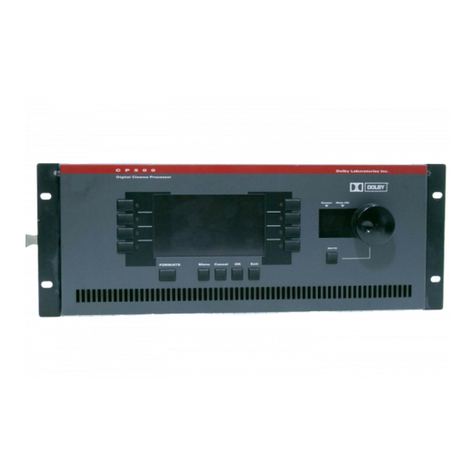
Dolby Laboratories CP650 User manual

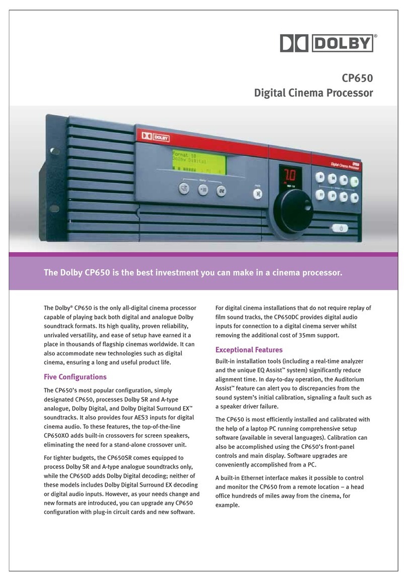
Model CP650
Digital Cinema Sound
Processor
Installation Manual
Issue 4 Part No. 91569

Dolby®Model CP650 Installation Manual
ii
Dolby Laboratories, Inc.
Corporate Headquarters
Dolby Laboratories, Inc.
100 Potrero Avenue
San Francisco, CA 94103-4813
Telephone 415-558-0200
Fax 415-863-1373
www.dolby.com
European Headquarters
Dolby Laboratories, Inc.
Wootton Bassett
Wiltshire, SN4 8QJ, England
Telephone (44) 1793-842100
Fax (44) 1793-842101
Dolby and the double-D symbol are registered trademarks of Dolby Laboratories. Auditorium Assist, EQ Assist, and
Surround EX are trademarks of Dolby Laboratories. All other trademarks remain the property of their respective owners.
© 2002 Dolby Laboratories, Inc. All rights reserved. Issue 4
Part No. 91569
S02/14315/14409
Software Version 2.1.x.x

Dolby®Model CP650 Installation Manual
iii
Table of Contents
List of Figures........................................................................................................vii
List of Tables..........................................................................................................ix
CP650 Operating System Software History............................................................x
Chapter 1 Introduction
1.1 About the Dolby CP650 Digital Cinema Processor .................................1-1
1.2 Hardware Configurations Available.........................................................1-2
1.3 Accessories...............................................................................................1-3
1.4 Dolby Catalog Number Listing ................................................................1-3
1.5 Specifications ...........................................................................................1-3
1.6 About Dolby Digital Surround EX...........................................................1-6
1.7 List of Formats Available.........................................................................1-8
1.8 How to Identify Types of Soundtracks.....................................................1-9
1.9 Regulatory Notices.................................................................................1-10
Chapter 2 Installation
2.1 Replacing an Existing Sound System.......................................................2-1
2.1.1 Before Playing the Film:.............................................................2-1
2.1.2 While Playing the Film:..............................................................2-1
2.1.3 Disconnect the Old System.........................................................2-2
2.2 Check Fuse and Bypass Mains Voltage Selector .....................................2-2
2.3 Mount the CP650......................................................................................2-3
2.4 Mount the Auditorium Assist Microphone...............................................2-4
2.5 Connect the CP650...................................................................................2-4
2.5.1 Motor-Start Relays......................................................................2-4
2.5.2 Remote Controls .........................................................................2-5
2.5.3 Solar Cell Reader Boards............................................................2-5
2.5.4 Analog Nonsync Sources............................................................2-8
2.5.5 Digital Audio Sources.................................................................2-8
2.6 Exploded View and Board Locations.....................................................2-12
Wiring Diagram- Input and Control...................................................................2-13
Wiring Diagram- Audio Outputs........................................................................2-14
Wiring Diagram- Audio Outputs forBiamplified Screen Speakers....................2-15
Wiring Diagram- Audio Outputs for Triamplified Screen Speakers..................2-16
System Signal Flow Chart..................................................................................2-17
Chapter 3 Front Panel and Alignment Overview
3.1 The CP650 Front Panel ............................................................................3-1
3.2 The Setup Control Panel...........................................................................3-6
3.3 Power Supply Voltage Test Points...........................................................3-8
3.4 Aligning the B-Chain and A-Chain..........................................................3-8

Dolby®Model CP650 Installation Manual
iv
Chapter 4 B-Chain Alignment
4.1 Check Theatre Equipment........................................................................4-1
4.2 Microphone Placement.............................................................................4-2
4.3 Initial Setup ..............................................................................................4-3
4.4 SPL (Sound Pressure Level) Calibration..................................................4-4
4.4.1 Initial Setup (CP650s with Cat. No. 791 Crossover)..................4-4
4.4.2 Calibration Procedure (All CP650s)...........................................4-4
4.5 Initial Output-Level Calibration...............................................................4-6
4.5.1 Main Channels ............................................................................4-6
4.5.2 Subwoofer Channel.....................................................................4-8
4.6 Crossover Setup (CP650 with Cat. No. 791)............................................4-9
4.7 Room Equalization.................................................................................4-17
4.7.1 Crossover Level Adjustment (for CP650s with Cat. No. 791) .4-17
4.7.2 Setting Coarse (Bulk) EQ .........................................................4-19
4.7.3 Setting Fine EQ (1/3 Octave)....................................................4-20
4.7.4 The EQ Assist Feature ..............................................................4-22
4.7.5 Setting Subwoofer Channel EQ................................................4-23
4.7.6 Final Output-Level Calibration.................................................4-25
4.8 Final Sound Check: Rotating Pink Noise...............................................4-28
Chapter 5 A-Chain Alignment
5.1 Overview ..................................................................................................5-1
5.2 Reverse-Scan Checkup: Projector ............................................................5-2
5.3 Analog Optical Alignment: Projector.......................................................5-2
5.4 Dolby Level Set........................................................................................5-4
5.5 Film-Path Alignment Check.....................................................................5-6
5.6 Cell Alignment Check..............................................................................5-7
5.7 Cell Wiring Check....................................................................................5-8
5.8 Azimuth Check.........................................................................................5-8
5.9 Focus Check .............................................................................................5-9
5.10 Optical HF Equalization (Slit-Loss EQ).................................................5-10
Chapter 6 Digital Soundheads
6.1 Mechanical Alignment .............................................................................6-1
6.2 Adjustment with Oscilloscope..................................................................6-2
6.3 Focus Adjustment.....................................................................................6-2
6.4 LED Brightness Confirmation and Adjustment .......................................6-3
6.4.1 Inboard Digital Readers ..............................................................6-3

Dolby®Model CP650 Installation Manual
v
Chapter 7 Final Adjustments
7.1 Setting Bypass Level................................................................................7-1
7.2 Setting Optical Surround Delay................................................................7-2
7.3 Setting Digital Surround Delay ................................................................7-3
7.4 Setting Dolby Digital Reader Delay.........................................................7-5
7.5 Nonsync Level Adjustment......................................................................7-7
7.6 Mono Level Trim and EQ Adjustment.....................................................7-8
7.7 Assigning Preset Fader Levels .................................................................7-9
7.8 Assigning User Button Formats .............................................................7-10
7.9 Assigning NS Button Format .................................................................7-11
7.10 Format 80/81 PCM Options ...................................................................7-11
7.11 Reversion Mode......................................................................................7-12
7.12 Auto Surround EX Disable.....................................................................7-12
7.13 Noise Gating...........................................................................................7-13
7.14 Running Auditorium Assist....................................................................7-14
7.14.1 Operation...................................................................................7-14
7.14.2 Establish Reference Measurements ..........................................7-15
7.14.3 Auditorium Sound Check..........................................................7-16
7.14.4 “FAIL” Parameters ...................................................................7-17
7.15 Noise Floor Optimization.......................................................................7-18
7.16 Clock Set ................................................................................................7-19
7.17 Date Set ..................................................................................................7-20
7.18 Mute Fade Time Adjustment..................................................................7-20
Chapter 8 Accessories
8.1 Introduction ..............................................................................................8-1
8.2 Cat. No. 779 Remote Control Installation................................................8-2
8.2.1 Remove the Housing...................................................................8-2
8.2.2 Make a Hole for the Interface Cable...........................................8-2
8.2.3 Connect to the Circuit Board ......................................................8-3
8.2.4 Set the Address Switch ...............................................................8-4
8.2.5 Assemble the Unit.......................................................................8-4
8.2.6 Connect to the CP650 .................................................................8-5
8.3 Cat. No. 771 Remote Fader Installation...................................................8-6

Dolby®Model CP650 Installation Manual
vi
Chapter 9 Maintenance and Troubleshooting
9.1 Print Cleanliness.......................................................................................9-1
9.2 Digital Soundhead Maintenance...............................................................9-1
9.2.1 Replacing the Cat. No. 701 LED Assembly ...............................9-2
9.2.2 Replacing the Cat. No. 700 Exciter Lamp ..................................9-5
9.3 CP650 Troubleshooting............................................................................9-6
9.3.1 Power Supply Voltage Ranges....................................................9-6
9.3.2 Exploded View and Board Locations .........................................9-7
9.3.3 The Event Log.............................................................................9-8
9.3.4 Troubleshooting Chart ................................................................9-8
Wiring Diagram- Power Supply, Black Cover...................................................9-18
Wiring Diagram- Power Supply, Gold Cover....................................................9-18
Exploded Views- Digital Readers ......................................................................9-19
Appendix A Software Operations
A.1 Display Information About This CP650 Unit .........................................A-1
A.2 Updating CP650 Software.......................................................................A-2
A.3 Transferring Settings Between Two CP650s ..........................................A-3
Appendix B Back Panel Connectors
Appendix C Optical Surround Level Trim
Appendix D Format Descriptions
D.1 Channel Definitions.................................................................................D-1
D.2 Format Definitions...................................................................................D-2
Appendix E External Control of CP650
E.1 Control via RS-232 Serial Data Port .......................................................E-1
E.2 Control via Remotes Connector ..............................................................E-4
Appendix F Setup and User Menus
F.1 CP650 Setup Menu.................................................................................. F-1
F.2 CP650 User Menu ................................................................................... F-4

Dolby®Model CP650 Installation Manual
vii
List of Figures
Figure 1–1 Surround Speaker/Amplifier Switching for 5.1 and Surround EX Modes ................1-7
Figure 1–2 Photograph of Film Soundtracks................................................................................1-9
Figure 1–3 Film Soundtrack Identification ..................................................................................1-9
Figure 2–1 Main Fuse Assembly..................................................................................................2-2
Figure 2–2 Star Washers and Rack-Mounting Screws.................................................................2-3
Figure 2–3 Cell Preamp Wiring Using Two 3-Conductor Shielded (Screened) Cables..............2-6
Figure 2–4 Cell Preamp Wiring Using One 5- or 6-Conductor Shielded (Screened) Cable........2-6
Figure 2–5 Cell Preamp Wiring Using Two 2-Conductor Shielded (Screened) Cable................2-7
Figure 2–6 Cell Preamp Wiring Using One 4-Conductor Shielded (Screened) Cable ................2-7
Figure 2–7 Cat. No. 790 S/PDIF Connections.............................................................................2-9
Figure 2–8 Cat. Nos. 794/778 AES/EBU and S/PDIF Jumper Selections and Connections.......2-9
Figure 2–8 Model CP650 Exploded View .................................................................................2-12
Wiring Diagram- Input and Control...........................................................................................2-13
Wiring Diagram- Audio Outputs................................................................................................2-14
Wiring Diagram- Audio Outputs forBiamplified Screen Speakers............................................2-15
Wiring Diagram- Audio Outputs for Triamplified Screen Speakers..........................................2-16
System Signal Flow Chart..........................................................................................................2-17
Figure 3–1 Front-Panel Controls..................................................................................................3-1
Figure 3-2 Front-Panel Display Showing All Possible Channels Active.....................................3-2
Figure 3-3 Front-Panel Display Showing a Dolby Digital Film Playing.....................................3-3
Figure 3-4 Front-Panel Display Showing Dolby Digital Surround EX Film Playing..................3-3
Figure 3-5 Front-Panel Display When Running Earlier Software ...............................................3-3
Figure 3–3 Fader Characteristic ...................................................................................................3-4
Figure 3–4 CP650 Operation and Setup Menu Control Buttons..................................................3-5
Figure 3–5 Setup Control Panel ...................................................................................................3-6
Figure 3–6 Power Supply Voltage Test Points.............................................................................3-8
Figure 4–1 EQ Microphone Placement........................................................................................4-2
Figure 4–2 Cat. No. 772A Board Jumpers for Cat. No. 791 Crossover.......................................4-9
Figure 4–3 Cat. No. 791 Board Jumpers for Screen Loss HF Boost............................................4-9
Figure 4–4 EQ Assist Operating Range .....................................................................................4-22
Figure 6–1 Digital Soundhead Adjustments.................................................................................6-1
Figure 6–2 Digital Video Oscilloscope Image—Focus Adjustment............................................6-3
Figure 6–3 Cat. No. 701 LED Brightness Adjustment.................................................................6-3
Figure 8–1 Cat. No. 779 Remote Control Functions....................................................................8-2
Figure 8–2 Location to Drill Wiring Hole....................................................................................8-3
Figure 8–3 Remote-Control Circuit-Board Connector.................................................................8-3
Figure 8–4 SW1 Address Switch Location ..................................................................................8-4
Figure 8–5 Connection of Remotes to the CP650........................................................................8-5
Dolby®Model CP650 Installation Manual
viii
Figure 9–1 Digital/Analog Track Wear........................................................................................9-1
Figure 9–2 LED Assembly Mounting Screws..............................................................................9-2
Figure 9–3 LED Assembly Wiring...............................................................................................9-2
Figure 9–4 LED Assembly Initial Gap Setting ............................................................................9-2
Figure 9–5 Scope Display of CP650 Video Test Point Signal.....................................................9-4
Figure 9–6 Adjust LED Assembly for Optimum Video Signal ...................................................9-4
Figure 9–7 LED Drive-Current Setting........................................................................................9-4
Figure 9–8 Digital Soundhead Exciter Lamp Replacement.........................................................9-5
Figure 9–9 Power Supply Voltage Test Points.............................................................................9-6
Figure 9–10 Model CP650 Exploded View .................................................................................9-7

Dolby®Model CP650 Installation Manual
ix
List of Tables
Table 1–1 Formats Supported by the CP650................................................................................1-8
Table 2–1 Solar Cell Preamp Board Connectors..........................................................................2-6
Table 2–2 Examples of Available Balanced ↔
↔↔
↔Unbalanced Adapters......................................2-11
Table 7–1 Surround Delays Based on Theatre Dimensions (in Feet) ..........................................7-4
Table 7–2 Surround Delays Based on Theatre Dimensions (in Meters)......................................7-5
Table 7–3 Typical Delay Settings for Dolby Digital Readers......................................................7-6
Table 7–4 Typical Delay Settings for Built-in Digital Readers ...................................................7-6
Table 9–1 Main Power Supply Voltage Ranges...........................................................................9-6
Table 9–2 Bypass Power Supply Voltage Ranges........................................................................9-6
Table B–1 Main Audio Output Connector Pinout.......................................................................B-1
Table B–2 Option Card I/O Connector Pinout with Cat. Nos. 790, 791, or 794 Installed..........B-2
Table B–3 Option Card I/O Connector Pinout with Cat. No. 778 Installed................................B-3
Table B–4 Dolby Digital Reader Input Connector Pinout ..........................................................B-4
Table B–5 Motor-Start Connector Pinout ...................................................................................B-5
Table B–6 Optical Input Connector Pinout.................................................................................B-5
Table B–7 Mic Input Connector Pinout ......................................................................................B-5
Table B–8 MIC MUX Connector................................................................................................B-6
Table B–9 Remote Unit and Remote Fader Connector Pinout ...................................................B-6
Table B–10 Six-Channel Analog Input Connector Pinout..........................................................B-7
Table B–11 Automation I/O Connector Pinout...........................................................................B-8
Table B–12 Automation I/O Connector Pins Used for Noise Gating .........................................B-9
Table B–13 Serial Data (RS-232) Connector Pinout ..................................................................B-9
Table D–1 Channel Definitions...................................................................................................D-1
Table D–2 Format Characteristics Chart...................................................................................D-10

Dolby®Model CP650 Installation Manual
x
CP650 Operating System Software History
V1.0.4.4
• First product shipments.
• Covered in Installation Manual, Issue 1.
V1.1.3.0
• Added support for Cat. No. 790 or 794 card: Dolby®Digital Surround EXTM
decoder and AES/EBU input for stereo pulse-code modulated (PCM) or
Dolby Digital bitstreams from consumer products.
• Covered in Installation Manual Addendum, Part No. 91743.
V1.1.5.0
• Added support for Cat. No. 779 remote control unit and Cat. No. 771 remote
fader unit. Covered in Remotes Installation Manual, Part No. 91733.
V1.1.7.0
• Added support for formats 92 and 93, Dolby SR input selections.
V1.2.x.y (where x and y may be any numbers)
• Added support for Auto Dolby Digital Surround EX switching, external
control via the RS-232 serial data port, and the rotating pink-noise feature.
• The EQ Assist®feature description was added to the installation manual.
• These features, along with all of the above updates, are covered in Installation
Manual, Issue 2.
V2.0.x.y (where x and y may be any numbers)
• Added the Auditorium AssistTM feature, which measures and stores a
characterization of the audio environment in a theatre, and allows periodic
checks and comparisons to qualify the sound system.
• Added support for the Cat. No. 778 Eight-Channel Digital I/O Card for use in
mixing studios.
• Added a noise floor optimization feature, which provides automatic gain
adjustments in the equalizers for improved noise performance.
• These features, plus all of the above updates, are covered in this installation
manual.

Dolby®Model CP650 Installation Manual
xi
V2.1.x.y (where x and y may be any numbers)
• Added support for the Cat. No. 790 Dolby Digital Surround EX
Decoder Card with four S/PDIF digital inputs. This card replaces the
Cat. No. 794, adding three additional S/PDIF digital inputs.
• Added support for the Cat. No. 791 Digital Crossover Card. This card plugs
into the Cat. No. 790, providing two- and three-way screen channel crossover
capability along with support for Left Extra/Right Extra screen channels.


Dolby®Model CP650 Installation Manual
1-1
Chapter 1
Introduction
1.1 About the Dolby CP650 Digital Cinema
Processor
The Dolby CP650 Digital Cinema Processor is a self-contained, all-digital cinema
processor capable of supporting Dolby®Digital, Dolby Digital Surround EXTM, Dolby
SR, Dolby A-type, and Academy mono film sound playback.
The CP650 provides inputs for two projector soundheads (both analog and digital), an
external six-channel processor, two nonsync sources, and a PA microphone. Its audio
outputs are balanced, with a multipin connector configured to the THX standard. The
CP650 is the first cinema processor to incorporate an Ethernet connection, enabling
theatre personnel to monitor the unit’s functions remotely from a PC.
For decoding analog soundtracks, the CP650’s state-of-the art design incorporates the
only digital implementations of Dolby A-type and Dolby SR decoding that meet
Dolby Laboratories’ own rigorous standards. Reductions in the cost of powerful
digital signal processing (DSP) circuitry have made it possible for the first time to
replace the analog circuitry previously necessary for the accurate reproduction of
A-type and SR soundtracks.
An easy-to-read LCD screen, plus simple front-panel format selection and control
buttons, makes it easy to install, operate, and maintain the CP650. Installation is
further simplified by built-in test instrumentation that includes a real-time analyzer.
Third-octave equalization, plus bass and treble trim controls, are provided for up to
seven channels (Left, Center, Right, Left Surround, Right Surround, Back Surround
Left, and Back Surround Right). A digital parametric equalizer is provided for
subwoofer equalization.
Easily programmed internal software manages most existing or likely future formats.
While an external PC is not required for setup, a full-featured software package is
available in several languages to facilitate the setup process. A serial connector for a
PC, an input for a calibration microphone multiplexer, and a variety of test points are
all accessible behind an access door on the front-panel. Built-in diagnostic software
runs automatically whenever the CP650 is turned on.
Calibration settings for a given theatre can be stored on a PC, and, if necessary,
transferred directly to another CP650, or other modules, minimizing the need for
additional calibration after repairs. As improvements to the CP650 digital control and
processing software are developed, the latest revisions will be downloadable from a
PC to the CP650. Updates to the digital processing used for Dolby Digital
soundtracks are included from time to time on Dolby Digital release prints, and

Dolby®Model CP650 Installation Manual Introduction
1-2
download automatically into the CP650 the first time such a print is played in the
cinema.
The standard Model CP650 includes a Cat. No. 790 (Cat. No. 794 in earlier units)
plug-in module featuring Dolby Digital Surround EX decoding, plus four-input
AES/EBU digital inputs accommodating PCM audio and Dolby Digital (consumer)
bitstreams.
Options available for the CP650 include a remote fader (Cat. No. 771), a remote unit
(Cat. No. 779) that duplicates many of the CP650’s front-panel controls, and an eight-
channel digital I/O card for use in mixing studios (Cat. No. 778).
1.2 Hardware Configurations Available
The CP650 is available in these versions:
Model CP650
• Dolby Digital soundtrack decoding
• Dolby A-type and SR analog soundtrack decoding
• Dolby Digital Surround EX decoding
• Four AES/EBU digital inputs
• Up to five AES/EBU digital outputs
• Six-channel analog input
Model CP650D
• Dolby Digital soundtrack decoding
• Dolby A-type and SR analog soundtrack decoding
• Six-channel analog input
• Upgradable to Dolby Digital Surround EX decoding and 4x AES/EBU digital
inputs by installing upgrade kit UEX/650, which includes a Cat. No. 790
plug-in circuit board.
Model CP650SR
• Dolby A-type and SR analog soundtrack decoding capability
• Six-channel analog input
• Upgradable to Dolby Digital soundtrack decoding by adding upgrade kit
UD/650, which includes a Cat. No. 773 plug-in circuit board
• Upgradable to Dolby Digital Surround EX decoding and 4x AES/EBU digital
inputs by installing upgrade kits UD/650 and UEX/650 (which includes a
Cat. No. 790 plug-in circuit board)

Dolby®Model CP650 Installation Manual Introduction
1-3
1.3 Accessories
• Upgrade kit UD/650, which includes the Cat. No. 773 circuit board
• Upgrade kit UEX/650, which includes the Cat. No. 790 circuit board
• Upgrade kit Cat. No. 735 Auditorium AssistTM, which includes a microphone
• Cat. No. 771 Remote Fader
• Cat. No. 778 Digital I/O Board, which provides up to eight channels of digital I/O
• Cat. No. 779 Remote Control Unit
• Upgrade Kit Cat. No. 791 Digital Crossover, which provides two-way or three-
way screen-channel crossover capability
1.4 Dolby Catalog Number Listing
Cat. No. 771 Remote Fader
Cat. No. 772A Analog I/O and Bypass Circuit Board
Cat. No. 773 Dolby Digital Film Decoder Circuit Board
Cat. No. 774A System Controller Circuit Board
Cat. No. 775 Backplane Board
Cat. No. 776 Power Supply Assembly
Cat. No. 777 Front-Panel Circuit Board
Cat. No. 778 Digital I/O Board
Cat. No. 779 Remote Control Unit
Cat. No. 790 Dolby Digital Surround EXTM Decoder with Four Digital Inputs
(this board replaces the earlier Cat. No. 794)
Cat. No. 791 Crossover Board (Cat. Nos. 773, 790, 772A, and 774A required)
Cat. No. 792 Bypass Power Regulator Circuit Board
Cat. No. 794 Dolby Digital Surround EX Decoder with Digital AES/EBU Input
Board (used in earlier CP650s; replaced by Cat. No. 790)
Cat. No. 797 Flash memory module (part of the Cat. No. 774A board)
1.5 Specifications
Signal Inputs
Optical: Balanced inputs for two projectors with stereo solar cells or analog LED
readers, digitally controlled gain and digital slit-loss EQ, power available for external
cell preamp circuits; 9-pin D-connectors
Digital film reader: Inputs for two Dolby digital soundheads; 25-pin D-connectors
Nonsync: Two stereo inputs, 21 kΩ, sensitivity: 0.2–4 V (NS 1),
0.06–1.5 V (NS 2); RCA-type phono connectors
Six-channel analog input: For external digital processor, 10 kΩ(L, R),
27 kΩ(C, Ls, Rs, SW), 300 mV operating level; 25-pin D-connector

Dolby®Model CP650 Installation Manual Introduction
1-4
Microphone: Balanced input for Auditorium Assist microphone, PA mic, or B-chain
alignment mic (or multiplexer), 15 V phantom power switchable via front-panel DIP
switch; rear-panel XLR and front-panel 9-pin D-connector
AES/EBU digital inputs: Accommodate stereo PCM audio at 48, 44.1, or 32 kHz,
also accept Dolby Digital bitstreams; input via 25-pin D-connector with optional
adapter boards (Cat. Nos. 790 or 778)
110Ω±20%, balanced (equipped with Cat. No. 778, four inputs), or
75Ω±20%, single-ended (equipped with Cat. No. 790, four inputs)
Signal Outputs
Balanced, output impedance: 100Ω(load >600Ω)
Maximum level: +26 dBu (15.5 V), balanced loads; +20 dBu (7.75 V), unbalanced
loads
Dolby level output adjust range: –31 to –12 dBu (20–780 mV)
Other Connections
Cat. No. 779 remote control unit and Cat. No. 771 remote fader connector (terminals
for stripped wires)
Connectors (front and rear) for external PC control and setup, RS-232C
(9-pin D-connector)
Hearing-impaired output: Center-weighted sum of L, R, and C; output
impedance 100Ω, output level 200 mV fixed; unbalanced (RCA-type phono
connector)
Automation connector for controlling and indicating format, fader select, and mute;
interface similar to Model CP65
Connector for Ethernet link, RJ-45
Dolby Decoding
5.1 channels: Dolby Digital and Dolby Digital Surround EX
Four channels: Dolby A-type
Two channels: Dolby SR
Dolby Pro Logic®

Dolby®Model CP650 Installation Manual Introduction
1-5
Loudspeaker Equalization
L, C, R, Ls, Rs, Bsl, Bsr: Digital 27-band, 1/3-octave, plus bass and treble control
Le, Re (when equipped with optional Cat. No. 791): Digital 27-band,
1/3-octave, plus bass and treble control
SW: Digital parametric with 12 dB cut capability
Distortion
Typically 0.005% in Dolby SR mode (output –10 dBu, input 10 dB over Dolby level)
Dynamic Range
Typically 99 dB with fader set to 7
Power Requirements
Main supply: 100–120 and 200–240 VAC, 50–60 Hz, 100 W maximum (including
built-in bypass power supply)
Unit designed to operate from a centrally switched power source
Dimensions and Weight
3-U rack-mount chassis; faceplate: 133 × 483 mm (5.25 × 19 inches)
Maximum projection behind equipment rack rail: 365 mm (14.4 inches)
Maximum projection in front of mounting plate: 38 mm (1.5 inches)
Net: 10.4 kg (23 lb)
Environmental Conditions
Operating: 0° to 40°C (32° to 104°F), forced-air cooling
Humidity: 20 to 80% relative humidity, noncondensing

Dolby®Model CP650 Installation Manual Introduction
1-6
1.6 About Dolby Digital Surround EX
Dolby Digital Surround EX adds a third surround channel to digital film sound, a
concept first envisioned by sound designers at Lucasfilm’s Skywalker Sound
postproduction facility. It gives sound mixers a new level of creative freedom.
Dolby Digital Surround EX is fully compatible with all current 5.1 digital sound
formats and theatre systems. Prints that use it play normally with current systems, and
provide the extra surround channel when played using a CP650 cinema processor
equipped with a Cat. No. 790 or 794 board.
A center screen channel is necessary to ensure the precise localization of front sounds
for all viewers, including those seated off to the sides. Dolby Digital Surround EX
brings similar benefits to the surround sound field. With Surround EX, a back
surround channel is reproduced by the speaker array at the back of the theatre, while
left and right surround is reproduced by the side arrays. This means that sounds can
now be positioned behind the audience, opening the door to exciting new effects,
such as true 360-degree pans.
The back surround channel also makes front-to-back and back-to-front transitions
more realistic. Flyovers really seem to pass overhead, rather than down the sides of
the theatre. Even ambient sound reproduction is improved, being less affected by the
width of the theatre. Equally important, the new back surround channel ensures that
even viewers seated close to the left or right of the theatre experience the total
surround ambience intended by the filmmaker.
The UEX650 kit upgrades the CP650D 5.1-channel digital cinema sound processor to
three surround channels that can play digital prints prepared with the Dolby Digital
Surround EX process. The installation requires wiring the surround speakers into left,
back (split into two groups), and right. Two power amplifier channels are required
for powering the two groups of back surround channel speakers. The figures below
show the surround signal distribution for conventional the 5.1-channel surround
format and for the Dolby Digital Surround EX format.
Auto Surround EX
On Dolby Digital soundtracks that contain a data bit signifying Surround EX
encoding, the CP650 will automatically switch to Dolby Digital Surround EX
decoding (operating software version 1.2 and above).

Dolby®Model CP650 Installation Manual Introduction
1-7
Left surround
Back surround left
Right surround
Back surround right
Dolby Digital
5.1 mode
Surround
amplifiers
Dolby CP650 Ls
Bsl
Bsr
10
Rs
Ls
Rs
Ls
Bsl
Bsr
Rs
Left surround
Back surround left
Right surround
Back surround right
Dolby Digital
Surround EX mode
Surround
amplifiers
Dolby CP650
Ls
Bsl
Bsr
U1
Rs
Ls
Rs
Ls
Bsl
Bsr
Rs
Bs
Figure 1–1 Surround Speaker/Amplifier Switching for 5.1 and Surround EX Modes

Dolby®Model CP650 Installation Manual Introduction
1-8
1.7 List of Formats Available
The formats supported by the CP650 are listed below. See Appendix D for complete
definitions of each format.
Table 1–1 Formats Supported by the CP650
Format Description Short Name
01 Academy mono optical Mono
04 Dolby A-type optical Dolby A-type
05 Dolby SR optical Dolby SR
10 Dolby Digital film Dolby Digital
11 External six-channel
13 Dolby Digital Surround EX film Surround EX
20 35 mm magnetic, L, C, R three-channel Three-channel mag
22 35 mm magnetic, four-channel Four-channel mag
42 70 mm Dolby A-type mag. mono surround 70 mm Dolby Stereo
60 Nonsync 1
61 Nonsync 2
64 Public-address center channel Public address, C
65 Public Address Surround Channels Public address, LsRs
66 Test Tone 320 Hz
70 Video PA Nonsync 1 Video PA (NS1)
71 Video mono Nonsync 1 Video Mono (NS1)
73 Video LCR Nonsync 1 Video LCR (NS1)
74 Video Pro Logic no SW Nonsync 1 Vid Pro Logic no SW
75 Video Pro Logic with SW Nonsync 1 Vid Pro Logic +SW
80 Bitstream Master Digital Input Master Digital In
81 Bitstream Master Digital + Surround EX Fmt 80 w/Surr. EX
85 Bitstream PCM Eight-Channel Input,
Ten-Channel Output (Le/Re Support) Five Ch. Screen
86 Bitstream PCM Eight-Channel Input,
Ten-Channel Output + Surround EX
(Le/Re Support) 5 Ch. Screen + EX
87 Ext. Six-Channel with Surround EX Fmt 11 w/Surr. EX
88 Six-Channel PCM
89 Six-Channel PCM + Surround EX Six-Channel PCM + EX
90 Six-Channel PCM
92 Dolby SR Two-track printmaster Dolby SR (Six-Ch In)
93 Dolby SR Two-track printmaster Dolby SR (NS1)
Other manuals for CP650
8
Table of contents
Other Dolby Laboratories Processor manuals

Dolby Laboratories
Dolby Laboratories CP650 User manual

Dolby Laboratories
Dolby Laboratories CP500 Quick start guide

Dolby Laboratories
Dolby Laboratories CP650 User manual

Dolby Laboratories
Dolby Laboratories 585 User manual

Dolby Laboratories
Dolby Laboratories CP650 User manual

Dolby Laboratories
Dolby Laboratories CP650 User manual

Dolby Laboratories
Dolby Laboratories CP650 User manual