DOLD SAFEMASTER M BG 5913.08/ 3 Series User manual

1BG 5913.08/_3_ _ _ / 03.11.20 / 314A
0272144
Die hier beschriebenen Produkte wurden entwickelt, um als Teil einer
Gesamtanlage oder Maschine sicherheitsgerichtete Funktionen zu
übernehmen. Ein komplettes sicherheitsgerichtetes System enthält in
der Regel Sensoren, Auswerteeinheiten, Meldegeräte und Konzepte für
sichereAbschaltungen.EsliegtimVerantwortungsbereichdesHerstellers
einer Anlage oder Maschine die korrekte Gesamtfunktion sicherzustel-
len. DOLD ist nicht in der Lage, alle Eigenschaften einer Gesamtanlage
oder Maschine, die nicht durch DOLD konzipiert wurde, zu garantieren.
Das Gesamtkonzept der Steuerung, in die das Gerät eingebunden ist,
ist vom Benutzer zu validieren. DOLD übernimmt auch keine Haftung für
Empfehlungen, die durch die nachfolgende Beschreibung gegeben bzw.
impliziertwerden.AufgrunddernachfolgendenBeschreibungkönnenkeine
neuen,überdieallgemeinenDOLD-Lieferbedingungenhinausgehenden,
Garantie-,Gewährleistungs- oderHaftungsansprüche abgeleitetwerden.
Sicherheitsbestimmungen
- Das Gerät darf nur von sachkundigen Personen installiert und in Betrieb
genommen werden, die mit dieser Betriebsanleitung und den geltenden
Vorschriften über Arbeitssicherheit und Unfallverhütung vertraut sind.
- Beachten Sie die VDE- sowie die örtlichen Vorschriften, insbesondere
hinsichtlich Schutzmaßnahmen.
- Durch Öffnen des Gehäuses oder eigenmächtige Umbauten erlischt
jegliche Gewährleistung.
- Montieren Sie das Gerät in einen Schaltschrank mit Schutzart IP 54 oder
besser; Staub und Feuchtigkeit können sonst zu Beeinträchtigungen
der Funktionen führen.
- Sorgen Sie an allen Ausgangskontakten bei kapazitiven und induktiven
Lasten für eine ausreichende Schutzbeschaltung.
- Die Sicherheitsfunktion muss bei Inbetriebnahme ausgelöst werden.
Das Eingangsmodul BG5913 kann nur in Verbindung mit der Steuereinheit
BH 5911 benutzt werden. Es erlaubt den Ausbau eines SAFEMASTER M
Systems auf bis zu 13 zweikanalige Sicherheitseingängen. Das Sicher-
heitssystemSAFEMASTERMdientdemsicherheitsgerichtetenFreigeben
und Unterbrechen eines Sicherheitsstromkreises. Es kann zum Schutz
von Personen und Maschinen in Anwendungen mit Not-Halt-Tastern,
Schutztüren, Lichtschranken mit Selbsttest (Typ 4) nach IEC/EN 61 496-1,
ZweihandschalternbeiPressenderMetallbearbeitung,sowie bei anderen
Arbeitsmaschinen mit gefährlichen Schließbewegungen (Type III A oder
III C nach EN 574) verwendet werden. Bei bestimmungsgemäßer Ver-
wendung und Beachtung dieser Anleitung sind keine Restrisiken bekannt.
Bei Nichtbeachtung kann es zu Personen- und Sachschäden kommen.
• entspricht
-Performance Level (PL) e und Kategorie 4 nach EN ISO 13849-1: 2008
-SIL-Anspruchsgrenze (SIL CL) 3 nach IEC/EN 62061
-Safety Integrity Level (SIL 3) nach IEC/EN 61508
• Eingangsmodul mit einer per Stufenschalter einstellbaren
Kombination von 3 der folgenden Funktionen:
- Berührungslos wirkende Schutzeinrichtung (BWS) Typ 4
mit manuellem oder automatischem Start
- Not-Aus (2-kanalig) mit manuellem oder automatischem Start
- Zweihandschaltung Typ IIIC nach DIN/EN 574
• 8 Eingänge für Befehlsgeber
• 2 Halbleiterausgänge zur Statusanzeige
• Drahtbruch und Kurzschlussüberwachung mit Fehleranzeige
• LEDs für Statusanzeigen
• Baubreite: 22,5 mm
Realisierung von sicherheitsgerichteten Steuerstromkreisen zum Schutz
von Personen und Maschinen.
Hinweis:ZurErweiterungvon SAFEMASTER
Mistdieses Eingangsmodul
ist für Anwendungen vorgesehen, bei denen gemischte Funktionen auf
einen gemeinsamen Ausgang wirken.
Es stehen weitere Eingangsmodule mit anderen Funktionskombinationen
zur Verfügung (z. B. BG 5913.08/_0_ _ _, BG 5913.08/_1_ _ _,
BG 5913.08/_2_ _ _, BG 5914.08/_0_ _ _, BH 5914.08/_0_ _ _ ,
BG 5914.08/_1_ _ _, BG 5915.08/_1_ _ _ oder BH 5915.08/_1_ _ _).
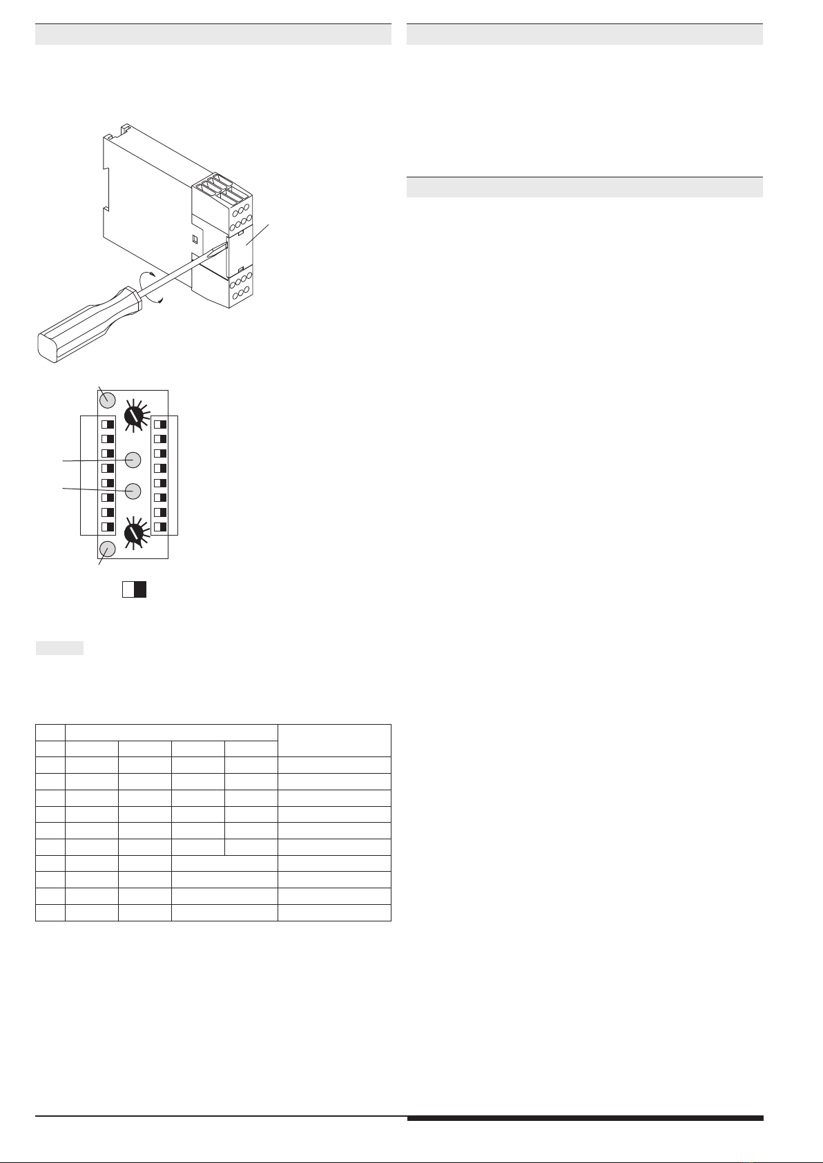
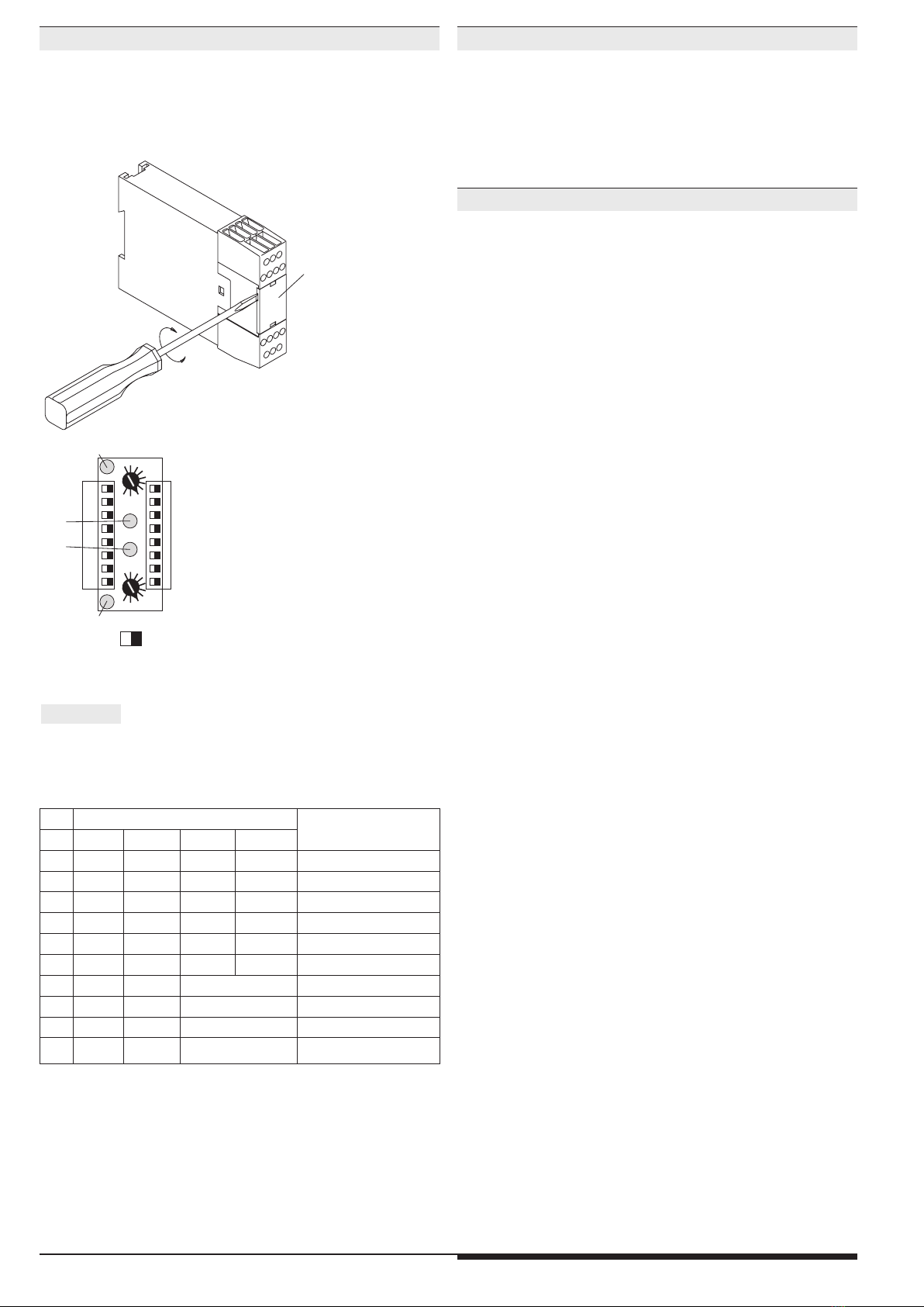
Klemmenbezeichnung Signalbeschreibung
(-) Bezugspotential für die
Ein- und Ausgänge
X1, X2 Steuerausgänge
S12, S14, S22, S24
S32, S34, S42, S44 Steuereingänge
Das multifunktionale Sicherheitssystem SAFEMASTER M besteht ma-
ximal aus
• der Steuereinheit BH 5911
• bis zu 3 Eingangsmodulen BG/BH 5913, BG/BH 5914, BG/BH 5915
• bis zu 3 Ausgangsmodulen BG 5912
• einem Diagnosemodul BG 5551 für CANopen oder
• einem Diagnosemodul BG 5552 für Profibus-DP
Die Steuereinheit verwaltet das gesamte System.
Mit den Ein-/Ausgangsmodulen lässt sich die Steuereinheit modular zu
einem multifunktionalen Sicherheitssystem erweitern.
Für die Zustandsmeldungen der einzelnen Module an eine übergeord-
nete Auswerteeinheit kann eines der nachfolgenden Diagnosemodule
angeschlossen werden:
• BG 5551 für CANopen
• BH 5552 für Profibus-DP
Grüne LEDs: leuchten, wenn das Modul die Freigabe für seine
zugeordneten Sicherheitsausgänge erteilt.
Weiße LEDs run 1/
run 2 und Ausgänge
48 und 58: zeigen den momentanen Zustand des Moduls an
Vor der Installation, dem Betrieb oder der Wartung des Geräts muss diese
Anleitung gelesen und verstanden werden.
Betriebsanleitung DEUTSCH
Multifunktionales Sicherheitssystem SAFEMASTER M
Eingangsmodul
BG 5913.08/_3_ _ _ Originalbetriebsanleitung
GEFAHR
Gefährliche Spannung.
Lebensgefahr oder schwere Verletzungsgefahr.
Vor Beginn der Arbeiten Anlage und Gerät spannungsfrei
schalten.
VORSICHT
Eine sichere Gerätefunktion ist nur mit zertifizierten Komponenten
gewährleistet!
Hinweise
Bestimmungsgemäße Verwendung
Sicherheitshinweise
ACHTUNG - AUTOMATISCHER START !
Gemäß IEC/EN 60 204-1 Punkt 9.2.5.4.2 darf nach dem Stillsetzen im
Notfall kein automatischer Start erfolgen. Deshalb muss in den Betriebs-
arten mit automatischem Start, eine übergeordnete Steuerung einen
automatischen Start nach einem Not-Aus verhindern.
Geräteeigenschaften
Anwendungen
Allgemeine Info zu SAFEMASTER M
Geräteanzeigen
Anschlussklemmen
Alle Angaben in dieser Liste entsprechen dem technischen Stand zum Zeitpunkt der Ausgabe.
Technische Verbesserungen und Änderungen behalten wir uns jederzeit vor.

2BG 5913.08/_3_ _ _ / 03.11.20 / 314A
Die Zuordnung des Moduls zu den Start-Tastern T1...T4 und den Sicher-
heitsausgängen (Relais) erfolgt über DIP-Schalter. Die Einstellung der
Funktionskombination erfolgt über die Drehschalter (Potis). Um Manipu-
lationen auszuschließen, sind die Einstellelemente durch eine Frontplatte
abgedeckt und redundant ausgeführt.
Platte
M2397_b
M8818_b
02
3
4
7
8
9
012
5
6
79
1
2
3
4
5
6
7
8
Relais
Erw.3
Erw.2
Erw.1
St
Erw.3
Erw.2
Erw.1
St
S1 S2
1
2
3
4
5
6
7
8
Start-
Taster
T1
T2
T3
T4
T1
T2
T3
T4
grüne LED "en 1"
grüne LED "en 2"
weiße LED
"run 1"
weiße LED
"run 2"
off on
• Einstellungen am Gerät sind vom Fachpersonal im spannungslosen
Zustand durchzuführen.
•Vor dem Abnehmen der Frontplatte muss für einen Potentialausgleich
gesorgt werden
Hinweis:
ST = Ausgänge der Steuereinheit
Erw. = Ausgänge der Ausgangsmodule
Jede Sicherheitsfunktion erteilt der Software des Moduls eine Freigabe.
Erst wenn alle 3 (bei Zweihandschaltung) bzw. 4 Freigaben vorliegen,
wird der Steuereinheit die Freigabe für die zugeordneten Sicherheits-
ausgänge erteilt.
Mit Ausnahme der Zweihandschaltung arbeitet jede Sicherheitsfunktion
für sich allein. Die Freigabe für die zugeordneten Sicherheitsausgänge er-
folgt, wenn bei allen Funktionen die Bedingung für die Freigabe erfüllt ist.
Die Funktion Zweihandschaltung arbeitet erst, wenn die zwei anderen
Sicherheitsfunktionen bereits ihre Freigabe erteilen. Die zwei Taster müs-
sen innerhalb 0,5 s betätigt werden, um eine Freigabe zu erteilen. Sobald
eine der anderen Sicherheitsfunktionen anspricht, müssen die zwei Taster
deaktiviert werden. Erst danach ist eine erneute Freigabe der anderen
Sicherheitsfunktionen möglich. Im nächsten Schritt lassen sich die unbe-
tätigten Taster nun erneut aktivieren.
Das Gerät darf gemäß in den Anwendungsbeispielen angeschlossen wer-
den. Durch das Parallel bzw. in Reihe Schalten der Bedientasten wird die
sichere Funktion der Geräte aufgehoben.
Die Tasten müssen so beschaffen und angeordnet sein, dass sie nicht auf
einfache Weise unwirksam gemacht oder unbeabsichtigt betätigt werden
können.
Der Sicherheitsabstand zwischen den Tasten und der Gefahrenstelle
muss so groß gewählt werden, dass beim Loslassen einer Taste die Ge-
fahrenstelle erst erreicht werden kann, nachdem die gefahrbringende Be-
wegung zum Stillstand gekommen ist.
Der Sicherheitsabstand „S“ wird nach folgender Formel berechnet:
S = V x T + C, wobei
a) Greifgeschwindigkeit V = 1 600 mm/s
b) Nachlaufzeit T (s)
c) Zuschlagwert C = 250 mm ist.
Wenn bei betätigten Bedientasten ein Eindringen in den Gefahrenbereich
sicher verhindert wird, z.B. durch eine Schutzabdeckung der Tasten, kann
für den Zuschlagwert C der Wert 0 eingesetzt werden. Der minimale Si-
cherheitsabstand muss aber in jedem Falle 100 mm betragen. Hierzu sie-
he auch DIN/EN 574.
Die beiden Zweihand-Taster dürfen nicht weiter betätigt werden, wenn ein
anderes Funktionsmodul, das auch auf die selben Ausgänge wirkt, seine
Freigabe nicht erteilt.
Es kann nur ein Funktionsmodul mit Zweihandschaltung im gesamten Sy-
stem vorhanden sein.
Poti Funktion an Klemmen: Startverhalten von
BWS / Not-Aus
S12-S14 S22-S24 S32-S34 S42-S44
0 Not-Aus Not-Aus Not-Aus BWS Auto-Start
1 Not-Aus Not-Aus Not-Aus BWS Hand-Start
2 Not-Aus Not-Aus BWS BWS Auto-Start
3 Not-Aus Not-Aus BWS BWS Hand-Start
4 Not-Aus BWS BWS BWS Auto-Start
5 Not-Aus BWS BWS BWS Hand-Start
6 Not-Aus Not-Aus Zweihand IIIC Hand-Start
7 BWS BWS Zweihand IIIC Hand-Start
8 Not-Aus BWS Zweihand IIIC Hand-Start
9 Not-Aus BWS Zweihand IIIC Auto-Start
Einstellen des Moduls Funktionsprinzip der kombinierten Eingänge
Funktion Zweihandschaltung

3BG 5913.08/_3_ _ _ / 03.11.20 / 314A
Bei der Funktion Not-Aus bzw. BWS müssen beide Signale innerhalb von
250ms aus dem inaktiven in den aktiven Zustand schalten. Spricht das
zweite Signal erst später an, müssen beide zuerst wieder inaktiv werden,
bevor eine neue Freigabe erfolgen kann.
Bei Hand-Start darf der Start-Taster nicht länger als 3 Sekunden betätigt
werden, um einen Start zu bewirken. Einem Modul können auch mehrere
Start-Taster zugeordnet werden.
Hinweis: Im Unterschied zu Not-Aus erfolgt bei der Funktion Licht-
schranke (BWS) keine Kurzschlusserkennung. Deswegen
sind am Modul nur selbsttestende BWS des Typs 4 nach
EN 61 496 anschließbar. Die Kurzschlussüberwachung der
BWS-Ausgänge muss in der BWS selbst erfolgen.
Funktionsfehler werden sowohl durch die weiße LED run 1 als auch durch
den Ausgang 48 angezeigt. Dabei bleibt die weiße LED run 2 an. Der
Ausgang 58 ist an, solange der Fehler ansteht. Er blinkt regelmäßig, wenn
eine Freigabe durch die zugeordneten Start-Taster wieder möglich ist:
Fehlercodes*
1) nicht benutzt
2) Eingriff in BWS oder Not-Aus betätigt
3) Zeit-Fehler: Die Signale einer Funktion sind nicht innerhalb der ge-
forderten Zeit aktiv geworden. (250 ms bei Not-Aus bzw. BWS, 0,5 s
bei Zweihandschaltung)
4) Fehler am Start-Taster (länger als 3 s betätigt, bereits beim Einschal-
ten oder beim Auftreten eines Fehlers betätigt)
5) Eingangsfehler (Kurzschluss, Unterbrechung)
6) Fehler in der Steuereinheit (Eingangs- oder Ausgangsfehler in der
Steuereinheit erkannt)
* Anzahl von kurzen Blinkimpulsen gefolgt von längerer Pause
Besonderheit bei Zweihandschaltung:
Sind am Modul beide Zweihandtaster inaktiv und alle andere Funktionen
aktiv und entweder durch Auto-Start oder über den Start-Taster freigege-
ben, sind der Ausgang 48 und die weiße LED run 1 dauernd aus, und der
Ausgang 58 dauernd ein.
Dauernd Aus Blinksignal Dauersignal
Ausgang
48
alle Relais inaktiv
wegen
Systemfehler
eine Funktion erteilt
keine Freigabe
Aktivierung der
zugeordneten
Sicherheits-
ausgänge erlaubt
LED
Run 1
Zweihandschaltung
nicht betätigt
(LED run 2 AN)
oder
alle Relais inaktiv
wegen System-
fehler
eine Funktion erteilt
keine Freigabe
(LED run 2 AN)
oder
Systemfehler wenn
LED run 2 AUS
oder blinkt
Aktivierung der
zugeordneten
Sicherheits-
ausgänge erlaubt
Ausgang
58
Aktivierung der
zugeordneten
Sicherheits-
ausgänge erlaubt
oder Systemfehler
keine Fehler mehr,
warten auf
Starttaster
eine Funktion erteilt
keine Freigabe
LED
Run 2
alle Relais inaktiv
wegen
Systemfehler
alle Relais inaktiv
wegen
Systemfehler
kein Systemfehler
Diese Fehler werden durch Blinkcodes der weißen LEDs run 1 und / oder
run 2 angezeigt. Die grünen LEDs sowie alle Ausgänge werden inaktiv.
Das System kann nur durch Aus- und wieder Einschalten der Versor-
gungsspannung neu gestartet werden.
Fehlercodes*
0) (beide weißen LEDs sind aus):
Ein anderes Modul zeigt einen Systemfehler an.
1) bis 4): nicht benutzt
5) unzulässige Funktionseinstellung:
- Die Drehschalter für Kanal 1 und 2 haben unterschiedliche oder
unzulässige Stellungen.
- Die Stellungen der DIP-Schalter der oberen Hälfte (Kanal 1) stimmen
nicht mit den entsprechenden Schalterstellungen der unteren Hälfte
(Kanal 2) überein.
6) LED run 1 blinkt: Unterspannung
LED run 2 blinkt: Überspannung
7), 8) nicht benutzt
9) Kopplungsfehler zwischen den Eingangsmodulen
Abschlussstecker nicht vorhanden.
Steuereinheit oder Eingangsmodul defekt
10), 11), 12), 13), 14) interne Fehler
*Anzahl von kurzen Blinkimpulsen gefolgt von längerer Pause
Funktion Not-Aus bzw. Lichtschranke (BWS)
Funktionsfehleranzeige
Systemfehleranzeige
Geräteanzeigen

4BG 5913.08/_3_ _ _ / 03.11.20 / 314A
Spannungsversorgung
Nennspannung UN:DC 24 V (kommt von der Steuer-
einheit BH 5911)
Spannungsbereich:
bei max. 5 % Restwelligkeit: 0,85 ...1,15 UN
Nennverbrauch: max. 60mA
(Halbleiterausgänge unbelastet)
Absicherung der Module: intern mit PTC
Eingänge
Steuerspannung
über X1, X2, 48.58: DC 23 V bei UN
Steuerstrom
über S12, S14, S22, S24,
S32, S34, S42, S44: je 4,5 mA bei UN
Mindestspannung
an S12, S14, S22, S24,
S32, S34, S42, S44DC 16 V
Halbleiterausgänge
Ausgang an Klemme
48 und 58: Transistorausgänge, plusschaltend
Ausgangsnennspannung: DC 24 V. max. 100 mA Dauerstrom.
max. 400 mA für 0.5 s
Interner Kurzschluss-, Übertemperatur-
und Überlastschutz
Bearbeitungszeiten (Zeit bis zugeordneter Ausgang reagiert):
Einschaltzeit typ. bei UN:
Eingangsmodule
BG 5913 Hand-Start automatischer Start
Anlauf Wiederanlauf
Not-Aus max. 80 ms max. 1 s max. 115 ms
Lichtschranken max. 80 ms max.1 s max. 115 ms
Schutztüren
oder Simulation:
max. 80 ms
Türschließung
max. 115 ms
Zweihandschaltung max. 85 ms
Abschaltzeit (Reaktionszeit): 33 ms
Allgemeine Daten
Nennbetriebsart Dauerbetrieb
Temperaturbereich: +0 ...+ 50 °C
Bei einer Betriebstemperatur von
50 °C sollte zwischen den Modulen
ein Abstand von ca. 3 - 5 mm einge-
halten werden.
Luft- und Kriechstrecken
Bemessungsstoßspannung /
Verschmutzungsgrad: 4 kV / 2 (Basisisolierung) IEC 60 664-1
EMV: IEC/EN 61 326-3-1, IEC/EN 62 061
Funkentstörung: Grenzwert Klasse A EN 55 011
Hinweis: Dies ist ein Gerät für den Betrieb in einer industriellen Um-
gebung. Beim Einsatz in einer anderen Umgebung kann es zu lei-
tungsgebundenen und auch gestrahlten Störungen führen.
Schutzart
Gehäuse: IP 20 IEC/EN 60 529
Klemmen: IP 20 IEC/EN 60 529
Gehäuse: Thermoplast mit V0-Verhalten
nach UL Subject 94
Rüttelfestigkeit: Amplitude 0,35 mm
Frequenz 10...55 Hz, IEC/EN 60 068-2-6
Schockfestigkeit
Beschleunigung: 10 g
Impulsdauer: 16 ms
Anzahl der Schocks: 1000 je Achse auf drei Achsen
Klimafestigkeit: 0 / 050/ 04 IEC/EN 60 068-1
Klemmenbezeichnung: EN 50 005
Leiteranschluss: DIN 46 228-1/-2/-3/-4
Leiterbefestigung: unverlierbare Plus- Minus- Klemmen-
schrauben M3,5 Kastenklemmen mit
selbstabhebendem Drahtschutz
Schnellbefestigung: auf Hutschiene IEC/EN 60715
Nettogewicht: 165 g
BG 5913.08/03MF0 DC 24 V
Artikelnummer: 0058703
Technische Daten Technische Daten
Standardtype

5BG 5913.08/_3_ _ _ / 03.11.20 / 314A
The product hereby described was developed to perform safety functions
as a part of a whole installation or machine. A complete safety system
normally includes sensors, evaluation units, signals and logical modules
for safe disconnections. The manufacturer of the installation or machine
is responsible for ensuring proper functioning of the whole system. DOLD
cannot guarantee all the specifications of an installation or machine that
was not designed by DOLD. The total concept of the control system into
which the device is integrated must be validated by the user. DOLD also
takes over no liability for recommendations which are given or implied in
the following description. The following description implies no modification
of the general DOLD terms of delivery, warranty or liability claims.
Safety Regulations
- This device must be installed and operated by trained staff who are
familiar with these instructions and with the current regulations for safety
at work and accident prevention.
- Pay attention to applicable local regulations, especially regarding safety
measures.
- Opening the device or implementing unauthorized changes voids any
warranty
- The unit should be panel mounted in an enclosure rated at IP 54 or
superior. Dust and dampness may lead to malfunction.
- Adequate fuse protection must be provided on all output contacts with
capacitive and inductive loads.
- The safety function must be triggered during commissioning
The input module BG 5913 can only be used with the control unit BH 5911.
It can extend the number of 2-channels safety inputs up to 13. The Multi-
Function Safety System is used to enable and interrupt a safety circuit in
a safe way. It can be used to protect people and machines in applications
with e-stop buttons, safety gates, light curtains with selftesting (Type 4)
acc. to IEC/EN 61 496-1, 2-hand controls for presses as well as other
production machinery with dangerous closing action (Type III A or III C to
EN574). When used in accordance with its intended purpose and following
these operating instructions, this device presents no known residual risks.
Nonobservance may lead to personal injuries and damages to property.
• According to
-Performance Level (PL) e and category 4 to EN ISO 13849-1: 2008
-SIL Claimed Level (SIL CL) 3 to IEC/EN 62061
-Safety Integrity Level (SIL 3) to IEC/EN 61508
• Input module for combination of 3 of the following functions to be set
via rotary switch:
- Light curtains (LC) type 4 with manual or automatic start
- E-stop 2-channel and manual or automatic start
- Two-hand function type IIIC according to DIN/EN 574
• The functions are selected via rotary switch
• 8 safety inputs
• 2 semiconductor outputs for status indication
• Broken wire and short circuit monitoring function with error indication
• LEDs for status indication
• Width: 22.5 mm
0272144
Realization of fail-safe control circuits for protection of people and ma-
chinery.
Note: This module is intended for applications in which mixed safety
functions affect one common output.
Further input modules with other combinations of functions are provided
(e.g. BG 5913.08/_0_ _ _, BG 5913.08/_1_ _ _ , BG 5913.08/_3_ _ _,
BG 5914.08/_0_ _ _, BH 5914.08/_0_ _ _, BG 5914.08/_1_ _ _,
BG 5915/_1_ _ _ or BH 5915.08/_1_ _ _).
Green LEDs: on, when all inputs are present and start
button activated.
White LEDs Run1/
Run 2 and outputs
48 and 58: indicate the current status of the module.
Before installing, operating or maintaining this device, these instructions
must be carefully read and understood.
Operating instructions ENGLISH
Multi-Function Safety System SAFEMASTER M
Input Module
BG 5913.08/_3_ _ _
Translation
of the original instructions
CAUTION
Safe operation of the device is only guaranteed when using certified
components!
DANGER
Dangerous voltage.
Electric shock will result in death or serious injury.
Disconnect all power supplies before servicing equipment.
Important Notes
Designated Use
Safety Notes
ATTENTION - AUTOMATIC START!
According to IEC/EN 60 204-1 part 9.2.5.4.2 and 10.8.3 it
is not allowed to
restart automatically after emergency stop. Therefore the machine control
has to disable the automatic start after emergency stop.
Terminal designation Signal designation
(-) Reference potential for
inputs and outputs
X1, X2 Control outputs
S12, S14, S22, S24
S32, S34, S42, S44 Control inputs
Connection Terminals
Indication
The maximum configuration of the SAFEMASTER M multi-function safety
system is as follows:
• the control unit BH 5911
• up to 3 input modules BG/BH 5913, or BG/BH 5914, BG/BH 5915
• up to 3 output modules BG 5912
• 1 diagnostic module BG 5551 for CANopen, or
• 1 diagnostic module BG 5552 for Profibus-DP
The BH 5911 controls the whole system.
The input/output modules can be used to expand the control unit in a
modular way into a multi-functional safety system.
To transmit status messages of the individual modules to a monitoring or
control unit, one of the following diagnostic modules may be connected:
• BG 5551 for CANopen
• BH 5552 for Profibus-DP
General Information SAFEMASTER M
Applications
Main Features
All technical data in this list relate to the state at the moment of edition. We reserve the right for
technical improvements and changes at any time.

6BG 5913.08/_3_ _ _ / 03.11.20 / 314A
The module is assigned to the start inputs and the safety outputs via the
DIP switches.
The combinations of individual functions are set via the rotary switches.
To prevent accidently adjustments, these elements are covered by a front
plate and are redundant.
plate
M2926_a
M8941_b
02
3
4
7
8
9
012
5
6
79
1
2
3
4
5
6
7
8
output
Mod3
Mod2
Mod1
Base
Mod3
Mod2
Mod1
Base
S1 S2
1
2
3
4
5
6
7
8
start
input
T1
T2
T3
T4
T1
T2
T3
T4
green LED "en 1"
green LED "en 2"
white LED
"run 1"
white LED
"run 2"
off on
• Settings to the unit must be performed by skilled personnel while
the unit is disconnected.
• Before the front cover is removed, antistatic precautions must be
observed.
Note:
Setting of the Modules
Each function activates an enabling signal in the module software. The
control unit is permitted to enable the assigned safety outputs only after
all 3 (for two-hands control) or 4 enablings have been given.
With the exceptionof two-hand control, each function works independently.
The assigned safety outputs are enabled if the precondition for enabling
has been met for all functions.
This function will only work when the other two functions have already
permitted enabling. To provide for enabling, the two buttons must be
pressed within 0.5 s. As soon as one of the other function reacts, the two
buttons must turn inactive before the others can be enabled again. Only
after that, the buttons can beactivated once more from an inactivated state.
The unit must be connected as specified in the application examples.
When the operating contacts are connected in parallel or in series, safe
functioning of the unit is cancelled.
The two-hand buttons must be designed and arranged in such a way as to
ensure that they cannot be disabled with easily, or pressed unintentionally.
The safety distance between the push buttons and the place of danger
must be large enough to make sure that after releasing a button, the place
of danger can onlybe reachedafter the dangerous movement has stopped.
The safety distance “S” is calculated according to the following formula:
S = V x T + C, where
a) gripping velocity V = 1 600 mm/s
b) overtravel time T (s)
c) and safety factor C = 250 mm.
When any access into the danger area, with operating keys pressed, is
safely prevented, e.g. by a protective cover for the keys, the safety factor
C may be set to the value 0. Generally, the minimum safety distance must
be 100 mm. In this respect, also see DIN/EN 574.
The two-hand control must be released when another function module
which affects the same outputs does not permit enabling.
The system maycomprise only one function module with two-hand control.
Sw. Function at Terminals Start behavior of
the LC / E-Stop
S12-S14 S22-S24 S32-S34 S22-S24
0 E-stop E-stop E-stop LC Autostart
1 E-stop E-stop E-stop LC Manual Start
2 E-stop E-stop LC LC Autostart
3 E-stop E-stop LC LC Manual Start
4 E-stop LC LC LC Autostart
5 E-stop LC LC LC Manual Start
6 E-stop E-stop Two-hand IIIC Manual Start
7 LC LC Two-hand IIIC Manual Start
8 E-stop LC Two-hand IIIC Manual Start
9 E-stop LC Two-hand IIIC Autostart
Setting of the Module Functional Principle of Combined Inputs
Function of the Two-Hand Control

7BG 5913.08/_3_ _ _ / 03.11.20 / 314A
In the Emergency stop or LC functions, both signals have to change from
inactive state into active state within 250 ms. If the second signal reacts
later, both changeover contacts must turn inactive before they can be
enabled again.
With manual start, all safety inputs must be active before the start button
can be pressed to trigger enabling. To start the system, do not keep the
start button pressed for more than 3 seconds. A module may also be
assigned several start buttons.
Note: Connect only self-testing light curtains of the type 4 acc. to EN
61496 to the module. Short-circuit monitoring of the inputs for
the LC must be done in the LC.
Function errors are indicated by the white LED Run 1 and by output 48;
the white LED Run 2 remains on. Output 58 is ON as long as the error is
pending; it flashes regularly, while waiting for the assigned start signal.
Error codes*
1) Normal interruption of function (e.g. Emergency stop)
2) Time error: (e.g. the second two-hand button is not pressed)
3) With gate monitoring: simulation input error (kept pressed for
too long)
4) Error at start input
5) Input error (short-circuit, interruption)
6) Error in the control unit (input or output error detected in
the control unit)
* number of short flashing impulses, followed by a longer space
Special with two-hand control:
When both two-hand buttons of the module are inactive while all other
functions are active and enabled either by autostart or via the start button,
output 48 and the white LED Run 1 are permanently OFF, and output 58
permanently ON.
Permanently OFF Pulsing Permanent ON
Output
48
all relays inactive
due to system
error
one input function
not available
Activation of the
assigned safety
outputs is
permissible
LED
run 1
Two-hand control
not activated
(LED run 2 ON)
or all relays in-
active
due to
system error
one input function
not available
(LED run 2 ON) or
system error when
LED Run 2 is OFF
or flashing
Activation of
the assigned
safety
outputs is
permissible
Output
58
Activation of the
assigned safety
outputs is permis-
sible or system
error
Error exists no
more,
waiting for
Start input
one input
function
not available
LED
run 2
all relays inactive
due to system
error
all relays inactive
due to system
error
No system error
These errors are indicated by flashing codes of the white LEDs Run 1 and/
or Run 2. The green LEDs and all outputs turn inactive. The system will
only restart after the supply voltage has been switched off and on again.
Error codes*
0) (both white LEDs are off):
Another input module indicates a system error.
1) To 4): not used
5) Incorrect setting of function:
- The rotary switches for channel 1 and 2 has different or
incorrect positions
- The setting of the 4 upper Dip-switches (channel 1) are not
identically to the 4 lower Dip-switches (channel 2)
6) LED Run 1 flashes: Undervoltage
LED Run 2 flashes: Overvoltage
7), 8) Not used
9) Connection error between the input modules
No terminating connector available.
· Control or input module defective
10), 11), 12), 13) a. 14) Internal errors
* number of short flashing impulses, followed by a longer space
E-Stop or Light Curtain (LC) Function Function Error Indication
Indication of System Errors:
Indication

8BG 5913.08/_3_ _ _ / 03.11.20 / 314A
Voltage Supply
Nominal voltage UN:DC 24 V (coming from the basic module
BH5911)
Voltage range:
with max. 5% residual ripple: 0.85 ... 1.15 UN
Nominal consumption: max. 60mA
(no load on semiconductor outputs)
Short-circuit protection
of the modules: internally with PTC
Input
Control voltage
via X1, X2, 48.58: DC 23 V at UN
Control voltage
via S12, S14, S22, S24,
S32, S34, S42, S44: 4.5 mA each at UN
Minimum voltage
on S12, S14, S22, S24,
S32, S34, S42, S44: DC 16 V
Semiconductor Outputs
Output at terminal 48 and 58: Transistor outputs, plus-connected
Output nominal voltage: DC 24 V, max. 100 mA constant current,
max. 400 mA for 0.5 s
Internal short circuit, overtemperature, and
overload protection
Reaction Times (time till reaction of the assigned output):
Typ. NO time with UN:
Input modules
BG 5913 Manual start Automatic start
First start Restart
Emergency stop max. 80 ms max. 1 s max. 115 ms
Light barriers max. 80 ms max. 1 s max. 115 ms
Two-hand control
max. 85 ms
Break time (reaction time): max. 33 ms
General Data
Operating mode: Continuous operation
Temperature range: ± 0 ...+ 50 °C
At an operating temperature of 50 °C
the modules must be mounted with
a distance of 3 - 5 mm.
Clearance and creepage
distances
rated impulse voltage /
pollution degree: 4 kV / 2 (basis insulation) IEC 60 664-1
EMC: IEC/EN 61 326-3-1, IEC/EN 62 061
Radio interference
suppression: Limit value class A EN 55 011
Remark: This device is designed for industrial ambient conditions.
When used in other environment, it is possible that wire bound or
radiated interference occurs.
Degree of protection
Housing: IP 20 IEC/EN 60 529
Terminals: IP 20 IEC/EN 60 529
Housing: Thermoplastic with V0 behavior
according to UL Subject 94
Vibration resistance: Amplitude 0.35 mm IEC/EN 60 068-2-6
Frequency 10…55 Hz,
Shock resistance
Acceleration: 10 g
Pulse duration: 16 ms
Number of shocks: 1000 per axis on three axes
Climate resistance: 0 / 050/ 04 IEC/EN 60 068-1
Terminal designation: EN 50 005
Wire connection: DIN 46 228-1/-2/-3/-4
Wire fixing: Box terminal with wire protection, remov-
able terminal strips.
Mounting: DIN rail IEC/EN 60 715
Weight: 165 g
Dimensions
Width x height x depth: 22.5 x 84 x 121 mm
BG 5913.08/03MF0 DC 24 V
Article number: 0058703
Technical Data Technical Data
Standard Type

9BG 5913.08/_3_ _ _ / 03.11.20 / 314A
0272144
Le produit décrit ici a été développé pour remplir les fonctions de sécurité
en tant qu'élément d'une installation globale ou d'une machine. Un systè-
me de sécurité complet inclut habituellement des détecteurs ainsi que des
modules d'évaluation, de signalisation et de logique aptes à déclencher
des coupures de courant sûres. La responsabilité d'assurer la fiabilité de
l'ensemble de la fonction incombe au fabricant de l'installation ou de la
machine. DOLD n'est pas en mesure de garantir toutes les caractéristi-
ques d'une installation ou d'une machine dont la conception lui échappe.
C'est à l'utilisateur de valider la conception globale du système auquel
ce relais est connecté. DOLD ne prend en charge aucune responsabi-
lité quant aux recommandations qui sont données ou impliquées par la
description suivante. Sur la base du présent manuel d'utilisation, on ne
pourra déduire aucune modification concernant les conditions générales
de livraison de DOLD, les exigences de garantie ou de responsabilité.
Consignes de sécurité
- L‘installation et la mise en service de cet appareil doivent être effectuées
par un personnel compétent familiarisé avec ce manuel d‘utilisation
ainsi qu‘avec les prescriptions en vigueur sur la sécurité du travail et la
prévention d‘accidents.
- Tenir compte des réglementations locales, en particulier celles concernant
les mesures de sécurité.
- L'ouverture de l'appareil ou des transformations non autorisées annulent
la garantie.
- Le relais doit être monté en armoire ayant un indice de protection au moins
IP 54; la poussière et l'humidité pouvant entraîner des disfonctionnements.
- S'assurer que les circuits de protection sont suffisants sur tous les
contacts de sortie en cas de charges capacitives et inductives.
- La fonction de sécurité doit être activée lors de la mise en service
Les modules d'entrée BG 5913 ne peuvent être utilisé qu'avec l'unité cen-
trale BH 5911 du système SAFEMASTER M. Ils permettent d'augmenter le
nombre d'entrées de sécurité bicanales jusqu'à 13. Le système de sécurité
SAFEMASTER M permet l'enclenchement et le déclenchement d’un circuit
électriquesécuritaire.llpeutêtre utilisé pour la protection de personnes et de
machines en combinaison avec des BP d’arrêt d’urgence, portes de sécu-
rité, et interprétation des barrières lumineuses avec autotest (Typ 4) selon
IEC/EN 61496-1,bimanuelles pour presses métalliques ainsi que pour
des machines avec des fonctions de fermeture dangereuses (Type III A ou
III C selon EN 574). En cas d'emploi approprié et d'observation de ces
instructions, on ne connaît aucun risque résiduel. Dans le cas contraire,
on encourt des riques de dommages corporels et matériels.
•satisfait aux exigences:
-Performance Level (PL) e et Catégorie 4 selon EN ISO 13849-1: 2008
-Valeur limite SIL demandée (SIL CL) 3 selon IEC/EN 62061
-Safety Integrity Level (SIL 3) nach IEC/EN 61508
• Module d'entrée pour la réalisation de:
- contrôles de barrières immatérielles (EPES) type 4
- arrêt d'urgence (2 canaux) avec démarrage automatique
ou manuel
- commande bimanuelle de type IIIC selon DIN/EN 574
• 8 entrées pour émetteurs d'ordres
• 2 sorties à semi-conducteurs pour l'affichage d'état
• Contrôle de la rupture de conducteur et des courts-circuits avec
affichage de défaut
• DEL pour affichages d'état
• Largeur utile 22,5 mm
Réalisation de circuits de commande sécuritaires pour laprotection des
personnes et machines.
Remarque: Ce module est prévu pour les applications SAFEMASTER M
et des utilisations où plusieurs fonctions de sécurité differéntes doivent
agir sur une sortie commune avec surveillance des portes par utilisation
de contacts inverseurs
D'autres fonctions de modules d'entrées sont à votre disposition sur
simple demande. P. ex. BG 5913.08/_0_ _ _, BG 5913.08/_0_ _ _,
BG 5913.08/_3_ _ _ , BG 5914.08/_0_ _ _ , BH 5914.08/_0_ _ _ ,
BG 5914.08/_1_ _ _, BH 5915.08/_0_ _ _ ou BG 5915.08/_1_ _ _.
Remarques
Avant l'installation, la mise en service ou l'entretien de cet appareil, on
doit avoir lu et compris ce manuel d'utilisation.
Manuel d'utilisation FRANÇAIS
Système de sécurité multifonctions SAFEMASTER M
Module d'entrée
BG 5913.08/_3_ _ _
Traduction
de la notice originale
DANGER
Tension dangereuse.
Une électrocution entraînera la mort ou des blessures graves.
Couper l'alimentation avant toute intervention sur l'installation et
l'appareil.
ATTENTION
La fonction de sécurité de cet appareil n'est garantie que dans la
mesure où les composants utilisés sont certifiés
Usage approprié
Remarques de sécurité
ATTENTION - Démarrage Automatique!
Selon IEC/EN 60 204-1 Art. 9.2.5.4.2 il est interdit d’effectuer un redé-
marrage automatique après un Arrêt d’urgence. Losqu’un démarrage
automatique est toutefois demandé, il est necéssaire de s'assurer qu’une
commandeprioritaireeffectuele blocage aprèsuneactiond’arrêtd’urgence.
Repérage des bornes Description
(-) Potentiel de référence pour les
entrées et sorties
X1, X2 Sorties de contrôle
S12, S14, S22, S24
S32, S34, S42, S44 Sorties de entrée
DEL vertes: s'allument quand le module libère les
sorties de sécurité correspondantes
DEL blanches run 1/
run 2 et sorties 48
et 58: indiquent l'état momentané de l'unité
centrale.
Affichages
Borniers
Le système de sécurité multifonctions SAFEMASTER Mse compose au
maximum de
• l'unité centrale BH 5911
• jusqu'à 3 modules d'entrée BG/BH 5913, BG/BH 5914, BG/BH 5915
• jusqu'à 3 modules de sortie BG 5912
• un module de diagnostic BG 5551 pour CANopen, ou
• un module de diagnostic BG 5552 pour Profibus-DP
L'unité centrale gère l'ensemble du système.
Les modules d'entrée / sortie permettent de transformer l'unité centrale
modulairement en un système de sécurité multifonctionnel.
Pour la signalisation d'état des différents modules à une unité d'analyse
en amont, on peut raccorder l'un des modules de diagnostic suivants:
• BG 5551 pour CANopen
• BH 5552 pour Profibus-DP
Informations générales à SAFEMASTERM
Utilisations
Caractéristiques
Toutes les caractéristiques données dans cette notice correspondent à l’édition en cours. Nous nous
réservonsledroit deprocéder àtout momentauxaméliorations oumodifications techniques nécessaires.

10 BG 5913.08/_3_ _ _ / 03.11.20 / 314A
plaque
M2808_a
M8942_a
02
3
4
7
8
9
012
5
6
79
1
2
3
4
5
6
7
8
relais
Erw.3
Erw.2
Erw.1
St
Erw.3
Erw.2
Erw.1
St
S1 S2
1
2
3
4
5
6
7
8
bouton
marche
T1
T2
T3
T4
T1
T2
T3
T4
DEL verte "en 1"
DEL verte "en 2"
DEL blanc
"run 1"
DEL blanc
"run 2"
off on
L'affectation de l'unité centrale aux boutons start T1...T4 et aux sorties de
sécurité (relais) s'effectue par interrupteurs DIP.
Le réglage de la fonction s'effectue au moyen de potentiomètres. Pour
éviter toute manipulation, les organes de réglage sont protégés par un
capot et exécutés de manière redondante.
ST = Sorties module de base
Erw. = Sorties modules de sortie
Remarques:
•Les réglages de l'appareil doivent se faire hors tension par un personnel
qualifié.
•Avant le retrait du plastron, prévoir une compensation de potentiel.
Réglage fonctionnement
Chaque fonction de sécurité donne son autorisation à la software du
module. L'unité centrale ne libère les sorties de sécurité correspondantes
que lorsque toutes les autorisations des 3 ou 4 entrées sont effectives.
A l'exception de la commande bimanuelle chaque fonction travaille pour
elle-même. La libération des sorties de sécurité correspondantes ne
s'effectue que si la condition de libération est disponible pour toutes les
fonctions.
La fonction bimanuelle n’est active que si les autres fonctions de sécurité
du bloc sont activées.
Les 2 BP doivent être activées dans un laps de temps de 0,5s.
Dès l’action sur une des autres fonctions de sécurité du bloc, l’appui sur
la bimanuelle doit être relachée et un réenclenchement peut être effec-
tué lorsque l’autre fonction de sécurité à l’origine du déclenchement est
réactivée et après réappui des BP de la bimanuelle.
L'appareilne doit être raccordé que selon les exemples d'utilisation donnés.
Le couplage de boutons de commande en parallèle ou en série annule la
sécurité de fonctionnement des appareils.
Les boutons doivent être conçus et disposés de manière à ne pas perdre
facilement leur efficacité ou être actionnés de manière intempestive.
La distance de sécurité entre les boutons et la zone dangereuse doit
être calculée de telle sorte qu'au relâchement d'un bouton on ne puisse
atteindre la zone dangereuse qu'une fois le mouvement dangereux arrêté.
Cette distance „S“ se calcule selon la formule suivante:
S = V x T + C, ou
a) vitesse de préhension V = 1 600 mm/s
b) temps d'inertie T (s)
c) valeur supplémentaire C = 250 mm
Si, une fois les boutons actionnés, la pénétration dans la zone dangereu-
se est empêchée efficacement, par exemple par un capot de protection,
on peut prendre 0 pour la valeur C. Mais dans tous les cas, la distance
de sécurité doit être au moins de 100 mm (voir également DIN/EN 574).
La commande bimanuelle doit à nouveau être relâchée quand un autre
module de fonction agissant sur les mêmes sorties ne donne pas sa
libération.
Il ne doit y avoir qu'un seul module de commande bimanuelle dans tout
le système.
Poti Fonction sur bornes: Comportement de démarrage
de EPES/AU
S12-S14 S22-S24 S32-S34 S42-S44
0 A.U. A.U. A.U. EPES Démarrage autom.
1 A.U. A.U. A.U. EPES Démarrage manuel
2 A.U. A.U. EPES EPES Démarrage autom.
3 A.U. A.U. EPES EPES Démarrage manuel
4 A.U. EPES EPES EPES Démarrage autom.
5 A.U. EPES EPES EPES Démarrage manuel
6 A.U. A.U. EPESman. IIIC Démarrage manuel
7 EPES EPES EPESman. IIIC Démarrage manuel
8 A.U. EPES EPESman. IIIC Démarrage manuel
9 A.U. EPES EPESman. IIIC Démarrage autom.
Réglage du module Principe de fonctionnement de la combinaison
Fonction commande bimanuelle

11 BG 5913.08/_3_ _ _ / 03.11.20 / 314A
Pour ces fonctions, les deux signaux doivent passer de l'état inactif à
l'état actif en l'espace de 250 ms. Si le second signal répond passé ce
délai, il faut que tous deux redeviennent inactifs pour qu'une nouvelle
libération puisse avoir lieu.
En démarrage manuel le bouton Start ne doit pas être actionné plus de
3 s pour que le démarrage ait lieu. Il est possible d'affecter au module
plusieurs boutons Start.
Remarque: Sur le module, on ne doit raccorder que des barrières à
contrôle automatique de type 4 selon EN 61496. Le contrôle
de court-circuit des entrées destinées aux barrières doit
avoir lieu dans celles-ci.
Les défauts de fonctionnement sont affichés aussi bien par la DEL blan-
che run 1 que par la sortie 48, la DEL blanche run 2 restant allumée.
La sortie 58 reste appelée aussi longtemps que le défaut persiste; elle
clignote régulièrement quand une libération par le(s) bouton(s) Marche
correspondant(s) est à nouveau possible:
Codes de défaut*
1) non attribués
2) Intervention dans dispositif EPES ou A.U.
3) Défaut de temps: Les signaux d'une fonction ne sont
pas devenus actifs durant le temps imparti (250 ms en A.U.
ou BI, 0,5 s en commande bimanuelle)
4) Défaut sur bouton Start (actionné pendant plus de 3 s,
à l'enclenchement ou à l'apparition d'un défaut)
5) Défaut d'entrée (court-circuit, coupure)
6) Défaut dans l'unité centrale (défaut d'entrée ou de sortie
détecté dans l'unité centrale)
* Nombre d'impulsions clignotantes brèves suivies d'une pause plus longue
Particularité de la commande bimanuelle:
Si, dans le module, les deux boutons de la commande bimanuelle sont
inactifs, que toutes les autres fonctions sont actives et qu'il y a libération
soit par le démarrage auto ou par le bouton Start, la sortie 48 et la DEL
jaune run 1 sont coupées en permanence et la sortie 58 alimentée en
permanence.
Arrêt continu Signal clignotant Signal continu
Sortie
48
Tous relais inactifs
suite à défaut
système
Une fonction
ne donne pas la
libération
L'activation des
sorties de sécurité
correspondantes
est autorisée
DEL
run 1
Couplage à 2 mains
non activé
(DEL run 2 active) ou
tous relais inactifs
suite à défaut
système
Une fonction
ne donne pas la
libération (DEL
run 2 allumée), ou
défaut système quand
DEL run 2 étein
ou clignote
L'activation des
sorties de sécurité
correspondantes
est autorisée
Sortie
58
L'activation des
sorties de sécurité
correspondantes est
autorisée, ou défaut
système
Plus de défaut,
attente de bouton
Start
Une fonction
ne donne pas
la libération
DEL
run 2
Tous relais inactifs
suite à défaut
système
Tous relais inactifs
suite à défaut
système
Pas de défaut
système
Les défauts sont affichés par les codes clignotants des DEL blanches run
1 et / ou run 2. Les DEL vertes ainsi que toutes les sorties deviennent
inactives. Le système ne peut être redémarré que par coupure et réenc-
lenchement de la tension d'alimentation.
Codes de défaut*
0) (les deux DEL blanches sont éteintes):
un autre module indique un défaut système.
1) à 4): non attribués
5) Réglage de fonction non autorisé:
- les interrupteurs pour canal 1 et 2 ont des positions différentes
ou une position non autorisée
- le réglage de 4 commutateurs supérieurs (canal 1) n'est pas
identique aux 4 commutateurs inférieurs (canal 2)
6) La DEL run 1 clignote: sous-tension
La DEL run 2 clignote: surtension
7), 8) non attribués
9) Défaut de couplage entre les modules d'entrée
connecteur d'extrémité absent
unité centrale ou module d'entrée défectueux
10), 11), 12), 13) et 14) Défauts internes
* Nombre d'impulsions clignotantes brèves suivies d'une pause plus longue
Fonction d'arrêt d'urgence ou barrières immatérielles (EPES) Affichages
Affichage des défauts de fonctionnement
Affichage des défauts système

12 BG 5913.08/_3_ _ _ / 03.11.20 / 314A
Tension d'alimentation
Tension assignée UN: DC 24 V (provient du module de
base BH 5911)
Plage de tensions
à 5 % max. d'ondulation
résiduelle: 0,85 ...1,15 UN
Consommation nomin.: max. 60 mA
(sorties à semi-conducteurs non
chargées)
Protection des modules: interne par PTC
Entrées
Tension de commande
par X1, X2, 48, 58: DC 23 V sous UN
Courant de commande
par S12, S14, S22, S24,
S32, S34, S42, S44: 4,5 mA sous UN
Tension minimale
sur S12, S14, S22, S24,
S32, S34, S42, S44DC 16 V
Sorties à semi-conducteurs
Sortie sur bornes 48 et 58: à transistors, commutation front positif
Tension assignée sortie: DC 24 V. max. 100 mA courant per -
manent max. 400 mA pour 0.5 s
Protection interne contre courts-
circuits, échauffement et surcharges
Temps de traitement (jusqu'à la réaction de la sortie corresp.):
Durée d'enclenchement réf. sous UN:
Temps de coupure
(temps de réaction): max. 33 ms
Caractéristiques générales
Type nominal de service service permanent
Plage de températures: + 0 ...+ 50 °C
Pour une température de service de
50°, une distance de 3 à 5 mm entre
les modules doit être respectée.
Distances dans l'air
et lignes de fuite
Catégorie de surtension /
degré de contamination: 4 kV / 2 (isolation de base) IEC 60 664-1
Reyonnement HF: 10 V / m IEC/EN 61 000-4-3
Tensions transitoires:
sur câbles d'alimentation A1-A2: 2 kV IEC/EN 61 000-4-4
CEM: IEC/EN 61 326-3-1, IEC/EN 62 061
Antiparasitage: seuil classe A EN 55 011
Remarque: Ceci est un appareil développé pour environement indu-
striel. Des problèmes soit conduits par cable ou émis peuvent appa-
raitre en d‘autres environnements.
Degré de protection
boîtier: IP 20 IEC/EN 60 529
bornes: IP 20 IEC/EN 60 529
Boîtier: thermoplastique à comportement V0
selon UL Subject 94
Résistance aux vibrations: amplitude 0,35 mm
fréquence 10...55 Hz,
IEC/EN 60 068-2-6
Résistance aux chocs
accélération: 10 g
durée d'impulsion: 16 ms
nombre de chocs: 1000 par axe sur 3 axes
Résistance climatique: 0 / 050 / 04 IEC/EN 60 068-1
Repérage des bornes: EN 50 005
Connectique: DIN 46 228-1/-2/-3/-4
Fixation des conducteurs: vis cruciformes imperdables M3,5 bornes
en caisson avec protection
conducteurs
Fixation instantanée: sur rail IEC/EN 60715
Dimensions
Largeur x hauteur x prof.: 22,5 x 84 x 121 mm
BG 5913.08/01MF0 DC 24 V
Référence: 0058703
Caractéristiques techniques Caractéristiques techniques
Version standard

13 BG 5913.08/_3_ _ _ / 03.11.20 / 314A
DE Not-Aus bzw. BWS
EN Emergency stop or light curtains
FR Arrêt d'urgence ou EPES
DE Zweihand-Betätigungen
EN Two-hand control
FR Contacts des portes
DE Funktionsdiagramme
EN Function Diagramms
FR Diagrammes de fonctionnement
Hinweis: Die Zeitangaben in einem Impulsdiagramm gelten auch für dieselbe Funktion in allen anderen Applikationen
Note: The times specified in a pulse diagram also apply to the same function in other applications.
Remarque: Les indications de temps d'un diagramme sont valables pour la même fonction dans toutes les applications.
two-hand 1,
NC contact
two-hand 1,
NO contact
two-hand 2,
NO contact
two-hand 2,
NC contact
two-hand
recognized as
operated
status: 1
two-hand
not pressed
2
operation of the
two buttons correct
t<0,5s
3
two-hand
is pressed
12
button2has been
confirmed too late
t=0,5s
error,
status1is
expected again
4
release of the,
button is recognized
at the first edge at
one of the4contacts
(now, status1is expected)
123
error has been
corrected
M8989_b
emergency stop,
LC, signal 1
emergency stop,
LC, signal 2
emergency stop
recognized as closed
status: 1
emergency
stop pressed
2
contacts
close correctly
t<0,250s
3
emergency
stop
deactivated
12
emergency stop is
deactivated,aline
is interrupted
t=0,250s
error,
status1is
expected again
4
operation of the
emergency stop is
recognized at the
first edge at one of
the2contacts
(now, status1is expected)
123
error has been
corrected
M8991

14 BG 5913.08/_3_ _ _ / 03.11.20 / 314A
DE Not-Aus und Hand-Start; Funktionen 1, 3 oder 5
EN Emergency stop and manual start; functions 1, 3 or 5
FR Arrêt d'urgence et démarrage automatique; fonctions: 1, 3 ou 5
DE Not-Aus und BWS, Auto-Start; Funktionen 0, 2 oder 4
EN Emergency stop and light curtain, Autostart; functions 0, 2 or 4
FR Arrêt d'urgence et EPES, démarrage automatique; fonctions: 0, 2 ou 4
DE Funktionsdiagramme
EN Function Diagramms
FR Diagrammes de fonctionnement
Hinweis: Die Zeitangaben in einem Impulsdiagramm gelten auch für dieselbe Funktion in allen anderen Applikationen
Note: The times specified in a pulse diagram also apply to the same function in other applications.
Remarque: Les indications de temps d'un diagramme sont valables pour la même fonction dans toutes les applications.
M9188
222222
supply
voltage
(A1/A2)
emergency stop 1,
S12-S14
emergency stop
or LC
S22-S24
emergency stop
or LC
S32-S34
emergency stop
or LC
S42-S44
enabling
LED en1en2
output 48,
LED run 1
(error code)
output 58
(error)
assigned
start button
: dark : permanently
on
: flashing code : constant flashing
M9186
2222 2232
t<
250ms
t=
250ms
emergency stop
or LC
S22-S24
emergency stop
or LC
S32-S34
emergency stop
or LC
S42-S44
enabling
LED en1en2
output 48,
LED run 1
(error code)
output 58
(error)
assigned
start button
supply
voltage
(A1/A2)
emergency stop 1,
contact1S12
emergency stop 1,
contact2S14
: dark : permanently
on
: flashing code

15 BG 5913.08/_3_ _ _ / 03.11.20 / 314A
DE 1 Not-Aus und 1 BWS, Auto-Start, 1 Zweihand IIIC; Funktion 9
EN 1 Emergency stop and 1 light curtain, Autostart, 1 two-hand control type IIIC; function: 9
FR Arrêt d'urgence et EPES, et démarrage automatique, commande bimanuelle IIIC; fonction: 9
DE Not-Aus und / oder BWS, Hand-Start, 1 Zweihand IIIC; Funktionen 6, 7oder 8
EN Emergency stop and / or light curtains, manual start, 1 two-hand control type IIIC; functions: 6, 7or 8
FR Arrêt d'urgence et / ou EPES, démarrage manuel, commande bimanuelle IIIC; fonctions: 6, 7 ou 8
DE Funktionsdiagramme
EN Function Diagramms
FR Diagrammes de fonctionnement
Hinweis: Die Zeitangaben in einem Impulsdiagramm gelten auch für dieselbe Funktion in allen anderen Applikationen
Note: The times specified in a pulse diagram also apply to the same function in other applications.
Remarque: Les indications de temps d'un diagramme sont valables pour la même fonction dans toutes les applications.
M9190
222
two-hand 1
S32-S34
two-hand 2
S42-S44
enabling of the other
modules assigned
to the same output
enabling
LED en1en2
output 48,
LED run 1
(error code)
output 58
(error)
supply
voltage
(A1/A2)
emergency stop
or LC
S12-S14
emergency stop
or LC
S22-S24
assigned
start button
: dark : permanently
on
: flashing code : constant flashing
M9192
22 3
: dunkel : Dauerlicht : Blinkcode
t<
0,5s t=0,5s
: gleichmäßiges Blinken
two-hand 1
S32-S34
two-hand 2
S42-S44
enabling of the other
modules assigned
to the same output
enabling
LED en1en2
output 48,
LED run 1
(error code)
output 58
(error)
supply
voltage
(A1/A2)
emergency stop
S12-S14
LC
S22-S24

16 BG 5913.08/_3_ _ _ / 03.11.20 / 314A
DE Not-Aus oder BWS; Funktionen 0, 1, 2, 3, 4 oder 5
EN Emergency stop or light curtains; functions: 0, 1, 2, 3, 4 or 5
FR Arrêt d'urgence ou EPES; fonctions: 0, 1, 2, 3, 4 ou 5
DE Not-Aus oder BWS, Zweihand Typ IIIC; Funktionen 6, 7, 8 oder 9
EN Emergency stop or light curtains, two-hand control type IIIC; functions 6, 7, 8 or 9
FR Arrêt d'urgence ou EPES, commande bimanuelle IIIC; fonctions: 6, 7, 8 ou 9
DE Anwendungsbeispiele
EN Application examples
FR Exemples d'utilisation
BG5913
X1
(-)
X2S12 S14 S22 S24 S32 S34 S42 S44
58 (-)48
M9194_b
L+
L-
LC
----
++++
waiting for start
error
error indication,
enabling active
emergency stop emergency stop
or LC
emergency
stop
or LC
trans-
mitter
trans-
mitter
OSSD OSSD
BG5913
X1
(-)
X2S12 S14 S22 S24 S32 S34 S42 S44
58 (-)48
M9196_b
L+
L-
--
++
T1 T2
waiting for start
error
error indication,
enabling active
emergency stop
or LC
emergency
stop
or LC
trans-
mitter
two-hand IIICOSSD

17 BG 5913.08/_3_ _ _ / 03.11.20 / 314A
DE Schaltbild
EN Circuit diagram
FR Schéma
DE Blockschaltbild
EN Block Diagram
FR Schéma-bloc
X1 S44 S42 S34 S32 S24 S22 S14 S12 X2 (-) 48 58(-)
input- module
PTC
input or control module
M8752_a
start-button
assignment
output
assignment
function management
en1 en2 run1 run2
S12 S14 S22 S24
S32 S34 S42 S44
48
58
X1
X2
(-)
(-)
M8741
S12 S24 S32 S34 S42 S44
X1 X2
S14 S22
(-)(-)
48
58
A1+
A1+

18 BG 5913.08/_3_ _ _ / 03.11.20 / 314A
DE Beschriftung und Anschlüsse
EN Labeling and connections
FR Marquage et raccordements
M11206
ø 4 mm / PZ 1
0,8 Nm
7 LB. IN
M10248
A
A = 10 mm
1 x 0,5 ... 4 mm2
1 x AWG 20 to 12
2 x 0,5 ... 1,5 mm2
2 x AWG 20 to 16
M10249
A
A = 10 mm
1 x 0,5 ... 2,5 mm2
1 x AWG 20 to 14
2 x 0,5 ... 1,5 mm2
2 x AWG 20 to 16
M10250
A
A = 10 mm
1 x 0,5 ... 4 mm2
1 x AWG 20 to 12
2 x 0,5 ... 1,5 mm2
2 x AWG 20 to 16
M10049
121
118
84
22,5
Hutschiene
DINEN60715
35
DE Maßbild (Maße in mm)
EN Dimensions (dimensions in mm)
FR Dimensions (dimensions en mm)
DE Montage / Demontage der Klemmenblöcke
EN Mounting / disassembly of the terminal blocks
FR Démontage des borniers ammovibles
DE Achtung:
Der Berührungsschutz der angeschlossenen Elemente und die Isolation der Zuleitungen sind für die höchste am
SAFEMASTER M System anliegende Spannung auszulegen
EN Attention:
Protection against contact of the connected elements and insulation of the supply lines must be laid out for the
maximum voltage applied to the SAFEMASTER M system
FR Attention:
La protection contre les contacts accidentels des éléments connectés et l‘isolement des fils conducteurs sont à
prévoir pour la tension maximale appliquée au system SAFEMASTER M.

19 BG 5913.08/_3_ _ _ / 03.11.20 / 314A
DE Sicherheitstechnische Kenndaten
bei Einstellung für NOT-HALT
EN Safety related data for E-stop
FR Données techniques sécuritaires
lors d'un réglage pour arrêt d'urgence
DE Sicherheitstechnische Kenndaten
bei Einstellung für BWS, Schutztür oder Zwei-Hand
EN Safety related data
for light curtains ,safety gates or two-hand
FR Données techniques sécuritaires lors d'un réglage pour BI
(barrières immatérielles), protection de porte ou bimanuelle
EN ISO 13849-1:
Kategorie / Category: 4
PL: e
MTTFd: 812,8 a (year)
DCavg: 96,0 %
dop: 365 d/a (days/year)
hop: 24 h/d (hours/day)
tcycle: 3600 s/cycle
=1 /h (hour)
IEC EN 62061
IEC EN 61508:
SIL CL: 3 IEC EN 62061
SIL 3 IEC EN 61508
HFT*): 1
DCavg: 96,0 %
SFF 99,2 %
PFHD: 2,34E-10 h-1
*) HFT = Hardware-Fehlertoleranz
Hardware failure tolerance
Tolérance défauts Hardware
EN ISO 13849-1:
Kategorie / Category: 4
PL: e
MTTFd: 2697,1 a (year)
DCavg: 96,0 %
dop: 220 d/a (days/year)
hop: 12 h/d (hours/day)
tcycle: 138 s/cycle
IEC EN 62061
IEC EN 61508:
SIL CL: 3 IEC EN 62061
SIL 3 IEC EN 61508
HFT*): 1
DCavg: 96,0 %
SFF 99,2 %
PFHD: 2,34E-10 h-1
*) HFT = Hardware-Fehlertoleranz
Hardware failure tolerance
Tolérance défauts Hardware
Anforderung seitens der Sicherheitsfunktion an das Gerät Intervall für zyklische Überprüfung der Sicherheitsfunktion
Demand to our device based on the evaluated neccessary safety level of the application. Intervall for cyclic test of the safety function
Consigne résultant de la fonction sécuritaire de l'appareil Interval du contrôle cyclique de la fonction sécuritaire
nach, acc. to, selon
EN ISO 13849-1
PL e with Cat. 3 or Cat. 4 einmal pro Monat / once per month / mensuel
PL d with Cat. 3 einmal pro Jahr / once per year / annuel
nach, acc. to, selon
IEC/EN 62061,
IEC/EN 61508
SIL CL 3, SIL 3 with HFT = 1 einmal pro Monat / once per month / mensuel
SIL CL 2, SIL 2 with HFT = 1 einmal pro Jahr / once per year / annuel

20 BG 5913.08/_3_ _ _ / 03.11.20 / 314A
DE EG-Konformitätserklärung
EN CE-Declaration of Conformity
FR Déclaration de conformité européenne
DE Zulassungen und Kennzeichen
EN Approvals and Markings
FR Homologations et sigles
Canada / USA
Seite 2 von 2
Anhang zur EG-Konformitätserklärung SAFEMASTER M Multifunktionales Sicherheitssystem :
Attachment to EG-Declaration of Conformity SAFEMASTER M Multifunction safety system :
L’ annex à Déclaration de conformité européenne SAFEMASTER M Système de sécurité multifonctions :
Produktbezeichnung
Type designation
Désignation du produit
Beschreibung
Description
Description
BH5911.03/00MF0 DC24V Steuereinheit
Control Unit
Unité centrale
BH5911.22/00MF0 DC24V
BG5912.04/00000 DC24V Ausgangsmodul
Output Module
Module de sortie
BG5912.48/00000 DC24V
BG5912.86/00000 DC24V Tv=0-20S Ausgangsmodul, rückfallverzögert
Output Module, off delay
Module de sortie, retardés à la chute
BG5912.86/00000 DC24V Tv=0-3S
BG5912.95/00000 DC24V Tv=0-3S
BG5913.08/00MF0 DC24V
Eingangsmodul
Input Module
Module d‘entrée
BG5913.08/01MF0 DC24V
BG5913.08/02MF0 DC24V
BG5913.08/03MF0 DC24V
BH5913.08/00MF0 DC24V
BG5914.08/00MF0 DC24V
BH5914.08/00MF0 DC24V
BG5915.08/01MF0 DC24V
BH5915.08/01MF0 DC24V
E. DOLD & SÖHNE KG • D-78120 Furtwangen
e-mail: dold-relays
@dold.com • internet: http://www.dold.com
•
Bregstraße 18 • Telefon 0 77 23 / 654-0 • Telefax 0 77 23 / 654-356
Table of contents
Languages: