manuals.online logo
Brands
  1. Home
  2. •
  3. Brands
  4. •
  5. Reer
  6. •
  7. Safety Equipment
  8. •
  9. Reer SV MR0 User manual

Reer SV MR0 User manual

SV MR0 - SV MR0 U QUICK START SAFETY GUIDE
REER S.p.A. Via Carcano 32, 10153 Torino Italia - Tel. +39 0112482215 r.a. Fax +39 011859867 - Internet: www.reersafety.com - e-mail: info@reer.it 1/2
A) CONTENUTO IMBALLO - PACKAGE CONTENTS –CONTENU DE L’EMBALLAGE - PACKUNGSINHALT - CONTENIDO DEL EMBALAJE
SV MR0 - SV MR0 U - Modulo di Sicurezza per Controllo Velocità / La presente guida di installazione
SV MR0 - SV MR0 U - Safety Module for Speed Monitoring / This quick installation guide
SV MR0 - SV MR0 U - Module de sécurité pour la contrôle de la vitesse / Le présent guide d’installation
SV MR0 - SV MR0 U - Sicherheitsmodul zur Drehzahlüberwachung / Die vorliegende Installierungsanleitung
SV MR0 - SV MR0 U - Módulo de seguridad para el control de la velocidad / La presente guía de instalación
Per installare e utilizzare in modo corretto e sicuro il modulo, è NECESSARIO consultare il manuale contenuto all’URL:
SV MR0 - SV MR0 U
To guarantee a correct and safe installation and operation of the module, it is MANDATORY to consult the user manual contained at URL:
Pour installer et utiliser correctement et en sécurité le module, il est NECESSAIRE de consulter le manuel d’instruction qui est contenu à l'URL:
Um das Modul korrekt und sicher zu installieren und zu verwenden,MÜSSEN Sie das unter der URL enthaltene Handbuch konsultieren:
Para instalar y utilizar el módulo de forma correcta y segura, DEBE consultar el manual que se encuentra en la URL:
www.reersafety.com/it/en/products/safety-interfaces
Altre condizioni o limitazioni d’uso sono presenti integralmente sul manuale
Other conditions or limitations for use are available in the manual
D'autres conditions ou limitations d'utilisation figurent dans le manuel dans son intégralité
Weitere Bedingungen oder Einschränkungen für die Verwendung finden Sie im Handbuch
Otras condiciones o limitaciones de uso se encuentran en el manual en su totalidad
➔I valori di sicurezza, i dati tecnici, le condizioni di garanzia e la Dichiarazione di Conformità sono contenute integralmente nel manuale.
➔The safety values, technical data, warranty conditions and Declaration of Conformity are fully contained in the manual.
➔Les valeurs de sécurité, caractéristiques techniques les conditions de garantie et la Déclaration deConformité sont contenues dans le manuel dans leur intégralité.
➔Die Sicherheitswerte, Technische Daten, Garantiebedingungen und Konformitätserklärung sind vollständig im Handbuch enthalten.
➔Los valores de seguridad, datos técnicos, las condiciones de garantía y la Declaración de Conformidad se encuentran en el manual en su totalidad.
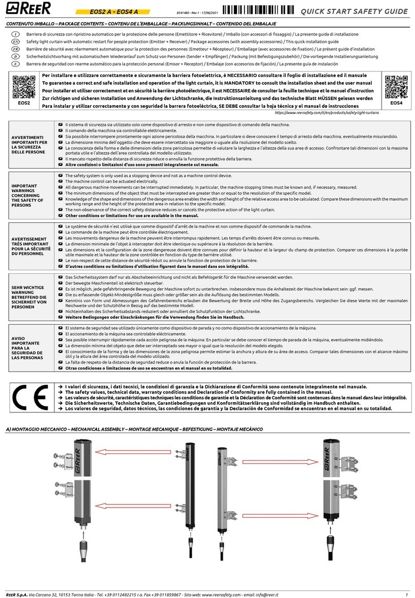
B) MONTAGGIO MECCANICO - MECHANICAL ASSEMBLY - MONTAGE MECANIQUE - BEFESTIGUNG - MONTAJE MECÁNICO
Leave enough space between the module and the top and bottom of the housing to enable air circulation and to avoid excessive heating.
Take into account the internal heating when mounting several modules side by side. The environmental conditions must be observed for every module and, in order to
avoid overheating, maintain between them one minimal distance of 2cm.
Le operazioni che seguono devono essere effettuate in assenza di alimentazione.
Fissare il modulo alla barra DIN premendolo delicatamente fino a sentire lo scatto del bloccaggio. Per rimuovere un modulo è necessario tirare verso il basso (utilizzando un
cacciavite) il gancio di arresto posto sul retro del modulo; sollevare quindi il modulo dal basso e tirare.
Do not apply power supply before carry out the following operations.
Fasten the module to the DIN rail. Press the unit gently until you feel it snap into place. To remove the module, use a screwdriver to pull down the locking latch on the back of
the unit; then lift the unit upwards and pull.
Les opérations suivantes doivent être effectuées en l'absence d'alimentation.
Montez le module sur la barre DIN en appuyant doucement sur le module jusqu'à ce que vous entendiez le verrouillage du module. Pour démonter un module, vous devez tirer
vers le bas (à l'aide d'un tournevis) sur le crochet de retenue situé à l'arrière du module, puis soulever le module par le bas et tirer.
Die im Anschluss beschriebenen Vorgänge müssen bei unterbrochener Stromversorgung ausgeführt werden.
Befestigen Sie das Modul auf der DIN-Hutschiene, indem Sie es vorsichtig nach unten drücken, bis es einrastet. Um ein Modul zu entfernen, müssen Sie
(mit einem Schraubendreher) den Haltehaken auf der Rückseite des Moduls nach unten ziehen, dann das Modul von unten anheben und abziehen.
Las siguientes operaciones se deben llevar a cabo con la alimentación cortada.
Enganche el módulo a la barra DIN presionandolo delicadamente hasta que escuche el bloqueo del módulo. Para retirar un módulo debe tirar hacia abajo (con un destornillador)
del gancho de retención en la parte posterior del módulo, luego levante el módulo por la parte inferior y tire.
C) MORSETTIERE DEL MODULO / TERMINAL BLOCKS OF MODULE / BORNIERS DU MODULE /ANSCHLUSSKLEMMEN DES MODULS / TERMINALES DEL MÓDULO
TERMINAL
SIGNAL NAME
TYPE OF SIGNAL
DESCRIPTION
1
24VDC
Power supply
Operating voltage (+24VDC )
2
SENSOR1_24VDC
Output
Sensor1 supply (+24VDC)
3
SENSOR1_GND
Output
Sensor1 supply (GND)
4
SENSOR1_IN
Input
Sensor1 input
9
0VDC
Power supply
Operating voltage (GND)
10
SENSOR2_24VDC
Output
Sensor2 supply (+24VDC)
11
SENSOR2_GND
Output
Sensor2 supply (GND)
12
SENSOR2_IN
Input
Sensor2 input
17
CURRENT1A
Input
Current path 1A (relay contacts)
18
-
--
-
19
-
-
-
20
CURRENT1B
Output
Current path 1B (relay contacts)
5
ENABLE_24VDC
Input
Enable plus-switching
6
ENABLE_GND
Output
Enable ground-switching
7
AUTO
Input
Automatic mode selection
8
MANUAL
Input
Manual mode selection
13
FAULT
Output
Transistor output "Fault"
14
OVERSPEED (SV MR0)
UNDERSPEED (SV MR0 U)
Output
Transistor output "Overspeed" (or "Underspeed")
15
FBK_OUT
Output
Feedback circuit output
16
FBK_IN
Input
Feedback circuit input
21
CURRENT2A
Input
Current path 2A (relay contacts)
22
-
-
-
23
-
-
-
24
CURRENT2B
Output
Current path 2B (relay contacts)
D) CONFIGURAZIONE - CONFIGURATION - CONFIGURATION - KONFIGURIERUNG - CONFIGURACIÓN
Tramite i tre selettori rotativi sul pannello frontale è possibile configurare il modulo:
By means of the three rotary switches on the frontal panel it is possible to configurate the module:
Les trois commutateurs rotatifs du panneau avant permettent de configurer le module:
Mit den drei Drehschaltern auf der Frontplatte können Sie das Modul konfigurieren:
Mediante los tres interruptores rotativos del panel frontal se puede configurar el módulo:
8541476 - 27/05/21 - Rev.0
SV MR0 - SV MR0 U QUICK START SAFETY GUIDE
REER S.p.A. Via Carcano 32, 10153 Torino Italia - Tel. +39 0112482215 r.a. Fax +39 011859867 - Internet: www.reersafety.com - e-mail: info@reer.it 2/2
Starting the configuration:
Set the 3 switches to configuration position 0/P
Switch on the power supply of the device
SWITCH / LED
OPERATION / RESULT
(1), (4)
(2)
1.
The LED CONF is blinking
Adjust Potentiometer P1 from
the position 0/P to the needed
Value
2.
During the rotation, the led
ENA lapse by every Step
(check with this visualization
the corrected value)
3.
System resting in
Configuration-Mode Waiting
for input P2
4.
The LED CONF is still blinking
E) SEGNALAZIONI - STATUS INDICATORS - INDICATEURS - STATUSANZEIGEN - INDICADORES DE ESTADO
LED
COLOUR
NAME
BEHAVIOUR
IN2
YELLOW
Input Sensor IN2
ON, when a high signal at the input IN2 was detected.
IN1
YELLOW
Input Sensor IN1
ON, when a high signal at the input IN1 was detected.
K2
GREEN
Indicator Relay K2
ON when the safety output relay K2 is switched on.
K1
GREEN
Indicator Relay K1
ON, when the safety output relay K1 is switched on.
ENA
YELLOW
Indicator Enable
ON when the Enable inputs are logical on. In configuration mode this LED blinks rotating the
potentiometers (one blink for each step). In clear status (waiting for a restart command) this led blinks.
CONF
BLUE
Indicator Configuration
ON when device in configuration mode. Blinking when switches are in P position.
ON
GREEN
Power Supply Indicator
ON, when the safety module is powered.
FAULT
RED
Fault Indicator
ON, when an internal fault is detected.
Indicator Fault is flashing, when an external fault (i.e. the sensor-test) is detected.
F) SCHEMI DI CONNESSIONE –WIRING DIAGRAMS –SCHÉMAS ÉLECTRIQUES –SCHALTPLÄNE –ESQUEMAS DE CONEXIÓN
SV MR0 –Manual mode
SV MR0 –Automatic mode
SV MR0 U –Manual mode
SV MR0 U –Automatic mode
Consultare il manuale per il dettaglio dei cablaggi nei diversi modi di funzionamento.
Refer to the manual for details of wiring in the different modes of operation.
Consultez le manuel pour savoir comment s'effectue le câblage dans les différents modes de fonctionnement.
Einzelheiten zur Verdrahtung in den verschiedenen Betriebsarten finden Sie im Handbuch.
Consulte el manual para los detalles de cableado en los diferentes modos de operación.
SWITCH / LED
OPERATION / RESULT
(3)
(1)
Adjust Potentiometer P3 From
the position P to the needed
Value
1.
During the rotation, the led
ENA lapse by every Step
2.
Led CONF becomes fixed.
Wait until led CONF is blinking
twice (memorization)
Turn OFF the power
SWITCH / LED
OPERATION / RESULT
(3)
(1)
Adjust Potentiometer P2 From
the position 0/P to the needed
Value
1.
During the rotation, the led
ENA lapse by every Step.
2.
System resting in
Configuration-Mode Waiting
for Input P3
3.
The led CONF is still blinking

Other manuals for SV MR0

1

This manual suits for next models

1

Other Reer Safety Equipment manuals

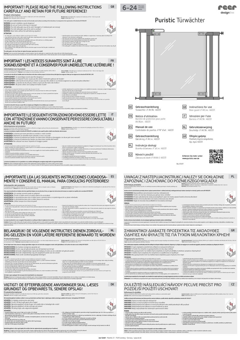
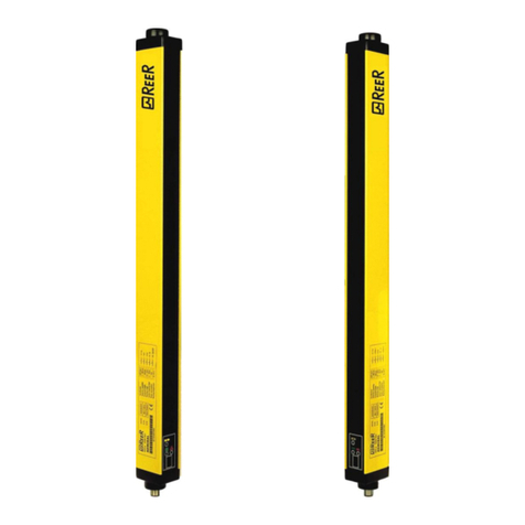
Reer Puristic User manual

Reer

Reer Puristic User manual

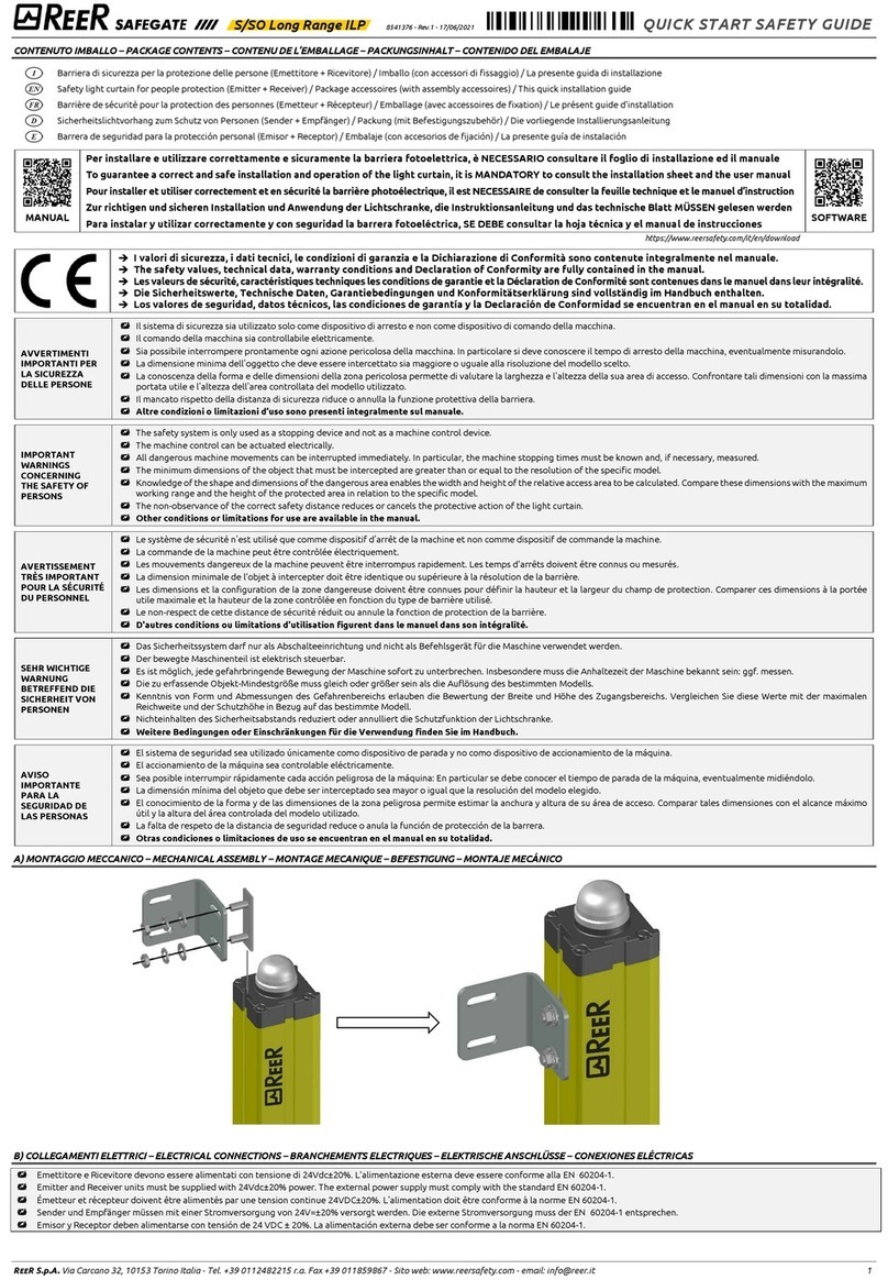
Reer SAFEGATE User manual

Reer

Reer SAFEGATE User manual

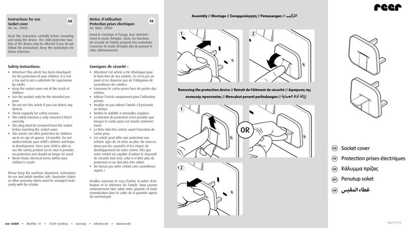
Reer 29030 User manual

Reer

Reer 29030 User manual

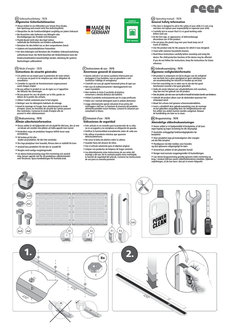
Reer 7878 User manual

Reer

Reer 7878 User manual

Reer MOSAIC MO2 User manual

Reer

Reer MOSAIC MO2 User manual

Reer MOSAIC MI8O4C User manual

Reer

Reer MOSAIC MI8O4C User manual

Reer EOS4 Series User manual

Reer

Reer EOS4 Series User manual

Reer 46101 User manual

Reer

Reer 46101 User manual

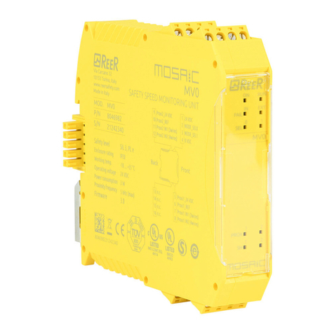
Reer MOSAIC MV0 User manual

Reer

Reer MOSAIC MV0 User manual

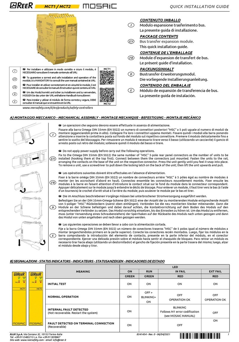
Reer Mosaic MCT1 User manual

Reer

Reer Mosaic MCT1 User manual

Reer VISION VX Quick start guide

Reer

Reer VISION VX Quick start guide

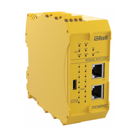
Reer MOSAIC M1S COM Master Module User manual

Reer

Reer MOSAIC M1S COM Master Module User manual

Reer JANUS TRX Quick start guide

Reer

Reer JANUS TRX Quick start guide

Reer EOS2 X User manual

Reer

Reer EOS2 X User manual

Reer AD SR2 Quick start guide

Reer

Reer AD SR2 Quick start guide

Reer SAFEGATE M SG BOX RST User manual

Reer

Reer SAFEGATE M SG BOX RST User manual

Reer FMC-SG Series User manual

Reer

Reer FMC-SG Series User manual

Reer VISION VX 152 Quick start guide

Reer

Reer VISION VX 152 Quick start guide

Reer SAFEGATE S User manual

Reer

Reer SAFEGATE S User manual

Reer ARGOLUX AS Series User manual

Reer

Reer ARGOLUX AS Series User manual

Reer EOS2 A User manual

Reer

Reer EOS2 A User manual

Reer MOSAIC MR2 User manual

Reer

Reer MOSAIC MR2 User manual

Popular Safety Equipment manuals by other brands

Spencer FA user manual

Spencer

Spencer FA user manual

3M Peltor LiteCom MT53H7A4600-NA manual

3M

3M Peltor LiteCom MT53H7A4600-NA manual

Guardian Fall Protection Beamer 2000 instruction manual

Guardian Fall Protection

Guardian Fall Protection Beamer 2000 instruction manual

FALL SAFE INSPECTOR FS874 instruction manual

FALL SAFE

FALL SAFE INSPECTOR FS874 instruction manual

ultraMEDIC ultraHEAD-LOCK II operating manual

ultraMEDIC

ultraMEDIC ultraHEAD-LOCK II operating manual

DeVilbiss MPV-616 Operation manual

DeVilbiss

DeVilbiss MPV-616 Operation manual

VERTIMA railoc Assembly and maintenance instructions

VERTIMA

VERTIMA railoc Assembly and maintenance instructions

Tractel blocfor 1.8A ESD instruction manual

Tractel

Tractel blocfor 1.8A ESD instruction manual

SECUMAR SECUMATIC 3001S Instructions for use

SECUMAR

SECUMAR SECUMATIC 3001S Instructions for use

Dräger X-plore 8000 Instructions for use

Dräger

Dräger X-plore 8000 Instructions for use

Petzl SEQUOIA manual

Petzl

Petzl SEQUOIA manual

babcockdavis Safe-T-Lume BEM-DS1 Installation, operation and maintenance manual

babcockdavis

babcockdavis Safe-T-Lume BEM-DS1 Installation, operation and maintenance manual

heightec RescuePack WK32 User instructions

heightec

heightec RescuePack WK32 User instructions

Petzl METEOR III+ Instructions for use

Petzl

Petzl METEOR III+ Instructions for use

Confio SOS Button User manua

Confio

Confio SOS Button User manua

Climbing Technology ICE HOOK manual

Climbing Technology

Climbing Technology ICE HOOK manual

Petzl IGUANE TECHNICAL NOTICE

Petzl

Petzl IGUANE TECHNICAL NOTICE

CMC Rescue 3D instructions

CMC Rescue

CMC Rescue 3D instructions

manuals.online logo
manuals.online logoBrands
  • About & Mission
  • Contact us
  • Privacy Policy
  • Terms and Conditions

Copyright 2025 Manuals.Online. All Rights Reserved.