Dolomite Mitos Installation manual

MITOS P
-
P
ump
PROGRAMMING INSTRUCTIONS

The Dolomite Centre Ltd.
3600051 - P-Pump API - programming instructions - v 1.3 Page 2 of 15
Contents
1 Summary 3
2 Introduction 3
3 Safety 3
4 RS232 protocol 3
5 Controlling the pump 4
5.1 General 4
5.1.1 IDLE (State: 0) 4
5.1.2 CONTROL (State: 1) 4
5.1.3 TARE (State: 2) 5
5.1.4 ERROR (State: 3) 5
5.1.5 LEAKTEST (State: 4) 5
5.2 Control strategy 5
6 Command/Response syntax 7
6.1 Response syntax 7
6.2 Command List 7
6.3 Status command response 10
6.4 Error Codes 11
7 Programming Example 13
8 Further Information 14

The Dolomite Centre Ltd.
3600051 - P-Pump API - programming instructions - v 1.3 Page 3 of 15
1 Summary
This document contains details of how to interface Mitos P-Pumps version 2 and 3 (serial
numbers 160200 or greater with a PC from your own application software. You can use any
programming language that can directly use a standard PC serial (“COM” port on any version of
Windows. Other operating systems that have FTDI drivers for virtual COM ports should also work
– Linux, Mac OS and Android – though Dolomite does not directly support these. For support for
P-Pumps earlier than 160200, please contact Dolomite Support – a similar but slightly less capable
API exists.
2 Introduction
This pump uses an embedded computer and a microcontroller to control all functions of the
display and pump. All communications takes place via RS232 using a simple ASCII protocol.
Communications are always one of:
•Set a control mode
•Read some value(s from the pump
•Write a value to the pump
3 Safety
It is responsibility of the user to ensure that all pressure equipment used with the Mitos P-Pump
complies with all relevant directives and guidelines. Always use suitable personal protective
equipment – e.g. safety glasses and shields etc. – when dealing with pressurised gases.
4 RS232 protocol
The standard interface to the P-Pump is USB. However, it is simple and convenient for the user
API to make the USB port expose a “virtual” COM port and this documentation assumes this. If
you need to use the device via raw USB please contact Dolomite Support.
To make the USB port appear as a COM port under Windows proceed as follows:
•Connect the P-Pump to your PC with a standard USB cable and install all requested USB
drivers.
•Open Device Manager (you may need administrator rights to do this .
•Find the entry for the P-Pump under Universal Serial Bus controllers
•Double click the
entry for the
Dolomite P-Pump
and, on the
Advanced tab,
check the “Load
VCP” checkbox
and click OK.
•Disconnect and
reconnect the
USB lead and Windows should now show a
new COM port listed under “Ports (COM & LPT ” – note the port number.

The Dolomite Centre Ltd.
3600051 - P-Pump API - programming instructions - v 1.3 Page 4 of 15
•If the new COM port cannot find a driver, force it to install the standard FTDI serial port
driver version 2.8.14 or later. This is available from Dolomite Support.
The RS232 protocol settings for the pump are:
57600 baud, 8 data bits, 1 stop bit, no parity, no handshaking.
Each command or response is terminated with a two character <CR><LF> combination (characters
13 and 10 .
Commands and responses take the form of ASCII strings, typically a single character, sometimes
plus parameters. All responses start with “#x” where x is the single character command sent.
Details of the command and response syntax are given in section 6 below.
5 Controlling the pump
Normally, the pump is used in pressure control mode but with the correct attached flow sensor
equipment, flow control mode can be used. These sections talks primarily about pressure
control, but are equally applicable to both control modes. More details about using flow control
are given below.
5.1 General
From the programming point of view the pump operates the following state machine. There are
two control modes and five pump states.
Control is achieved by moving the pump between modes/states with appropriate commands.
The ERROR state can be arrived at either spontaneously (a real physical error or through an
incorrect command. A detailed explanation of the characteristics of each state is given below.
5.1.1 IDLE (State: 0)
This state means the pump is not running any operation. If the pump is in the REMOTE_CONTROL
mode your application can issue any control command. Otherwise, it can only issue query
commands.
To return to IDLE when in CONTROL send a "P0" command. TARE and LEAKTEST states revert to
IDLE automatically on successful completion. The ERROR state can only return to IDLE using the
“C” command.
5.1.2 CONTROL (State: 1)
In this state the pump controls at a target pressure. Getting to this state is possible only from
IDLE by issuing a "control pressure" command, e.g. "P2500” – this starts CONTROL and sets the
target pressure to 2500mbar.

The Dolomite Centre Ltd.
3600051 - P-Pump API - programming instructions - v 1.3 Page 5 of 15
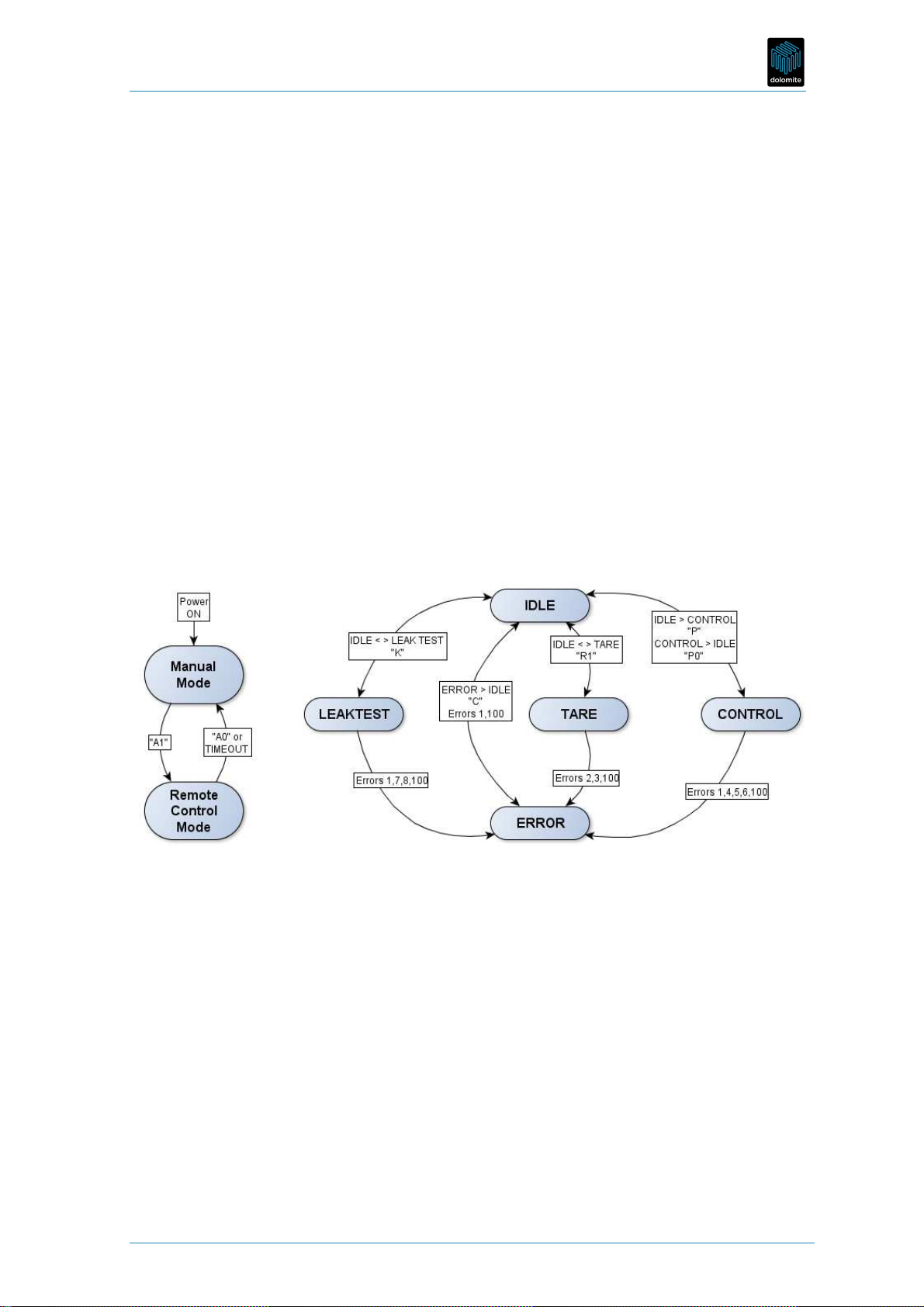
Issuing another control pressure command sets a new target but the pump stays in the CONTROL
state.
If your application issues a control pressure command when the pump is in any other state, the
command will be rejected and the pump will continue its current operation.
5.1.3 TARE (State: 2)
Your application should issue a “tare” command only when the status is IDLE. If the pump is in
any other state the command will be rejected. The pump automatically moves back to the IDLE
state when taring is complete.
During the tare operation, your application may see the TARE state, but that will depend on the
frequency of communication. Once the TARE is complete, any subsequent request for status
from the pump will only return IDLE or ERROR.
5.1.4 ERROR (State: 3)
The pump can get into the ERROR state from any other state if an error condition arises. The only
state to which the pump can move from ERROR is IDLE. To clear the ERROR state (move back to
IDLE the following conditions must be met:
•
The cause of an error must cease: you cannot clear the ERROR state unless the error
condition has been removed.
•
Your application must clear the ERROR state by explicitly sending a “C” command. This
ensures your application cannot "miss" any errors.
5.1.5 LEAKTEST (State: 4)
You can leak test the system by connecting a sealed chamber, a gas supply and setting the state
to LEAKTEST by issuing a “K” command. The test takes about 1 minute and performs a leak test at
two pressures - close to the supply and close to atmospheric pressure. The system is deemed
leak tight if neither test shows a change in pressure of more than ±5mbar/bar/minute. The test
assumes a system volume of about 30mls (the standard P-Pump chamber
1
.
When your application sees the status change back to IDLE, it can read the leak test result using
the “k” command. See command list below for details.
5.2 Control strategy
The pump only sends data in direct response to a command. As communication is asynchronous,
it is safest to write commands to the pump immediately following a completed response from the
pump to avoid collisions on the bus.
You can use the API to completely control the pump by setting the pump in full remote control
mode or leave the pump in manual mode and simply read pressure and state information back
from it when required. Full remote control mode has a timeout limit - you must send a
command to the pump at least once every 30 seconds or the pump will revert to manual mode
and IDLE. This acts as a safety watchdog in the event of PC, application or communications
failure.
The schematics below show a simple way of handling the data flow to and from the pump. There
are other methods that will work equally well or may be better or easier to implement in your
system. The system outlined has four main elements.
1. An interrupt driven timer
1
An acceptable leak rate of <±5mbar/bar/minute maximum is specified. Typical values are <±3mbar/bar/minute. The
apparent leak rate reported is inversely related to system volume – the specification assumes a standard 30ml volume
sealed system.

The Dolomite Centre Ltd.
3600051 - P-Pump API - programming instructions - v 1.3 Page 6 of 15
2. A first in first out (FIFO command queue
3. A “Response Pending” counter/flag
4. An interrupt driven response procedure
An interrupt based timer function is used to continually send “s” commands to the pump every
second. This will keep the remote
control session alive and provides a
continuous stream of current state and
pressure information from the pump
back to your application.
New control commands are simply
added to the tail of the FIFO command
queue and the timer interrupt sends
them on the next tick.
Having sent a command, the timer sets
the “Response pending” flag and won’t
send another command from the FIFO
queue until the flag is cleared. Thus
the Pending Response flag can be used
as a watchdog to ensure
communication with the pump is not
lost.
Responses are also conveniently received from the pump using an
interrupt routine. The exact procedure and sequence for handling
responses is not important but your application needs to take the
following steps:
•Handle only
complete responses.
A complete
response starts with
“#” and ends with
the <CR><LF>
terminator. In some
systems longer
responses may not
all appear
simultaneously –
you may need to
wait for the
response to be
completed.
•Check for ERROR states first and handle as required. Some errors can be reset
programmatically, some physical errors cannot and will require user intervention. See
section 6.4 below.
•Check the command acknowledgment character to make sure this command was
correctly interpreted by the pump and handle accordingly.

The Dolomite Centre Ltd.
3600051 - P-Pump API - programming instructions - v 1.3 Page 7 of 15
•Parse the actual response.
oFor “s” commands, parse out all the pump data and present to your application
GUI for display, logging etc. See section 6.3 for details.
oOK acknowledgments of other commands probably require no further action.
•After receiving a response, it is safe to check the FIFO queue for any commands waiting
and send them.
•Finally, set the “Pending Response” flag as required.
These are the basic steps required to control the pump. Exact implementations will vary
depending on the operating system and programming languages utilised.
6 Command/Response syntax
6.1 Response syntax
The pump responds to commands sent with a response that is always constructed the same way.
A standard response is of the form “#Ln” where L is the previous command and n is the command
acknowledgment value.
Command acknowledgment values are:
Response description
V
alue (
n
)
CMD_ACCEPTED
0
CMD_REJECT_
pump
_BUSY
1
CMD_REJECT_
pump
_ERROR
2
CMD_REJECT_MANUAL
3
CMD_REJECT_INVALID_ARG
4
CMD_REJECT_WRONG_NUM_ARGS
5
CMD_REJECT_U
NKNOWN_CMD
6
CMD_REJECT_INVALID
8
Simply put, command acknowledgments where n is 0 have been accepted and actioned by the
pump. All other endings indicate some form of problem that your application will need to
address.
6.2 Command List
The tables below show a complete list of commands and responses available to control the pump.
All commands and responses are terminated with <CR><LF>.
ommand
Description
Pump State
(before
after)
ontrol
Mode
(before
after)
A1
Enter remote control mode
.
Response “#A0”
AN
Y
Man.
Remote
A0
Leave remote control mode
. If the pump is
controlling this will return the pump to IDLE and
vent.
ANY
IDLE
Remote
Man.

The Dolomite Centre Ltd.
3600051 - P-Pump API - programming instructions - v 1.3 Page 8 of 15
ommand
Description
Pump State
(before
after)
ontrol
Mode
(before
after)
Response “#A0”
If pump does not receive any command, e.g. a status query "s", for 30 seconds it will
automatically return to manual mode.
Your application
sends this to move the pump
out of ERROR state and back into IDLE. C will
also stop control and force the pump back to
IDLE.
You must explicitly clear all error conditions.
This ensures your application has noted the error
and corrected it. The ERROR state will not clear
unless any physical error condition has been
corrected.
ERROR
IDLE
(ANY IDLE
e
Returns text string
of the last error message.
This may a P-Pump specific error or an error
from the underlying micro controller board.
Note, this command will always return the last
error message no matter how old. The message
is only valid when the pump is in the ERROR
state. See section 6.4 below, Error codes, below
Returns two strings: date and error information
separated by <LF>.
ANY
[response
only
guaranteed
valid if in
ERROR state]
ANY
L
“L
pump
Z” sets display name on the pump to
“pump Z”. The label is limited to a max of 8
characters - alphanumeric plus underscores.
Name will be upper case only.
IDLE
Remote
l
Lower case L.
Returns current label on the pump,
e.g. “#lpump Z”
ANY
ANY
n
Returns the serial number for the pump
,
e.g. “#n160295”
ANY
ANY
T
Send "Tx" where x is UTC time in seconds since
1/1/1970 IDLE ANY
t
Responds "#txxxxxx" where xxxxxx is UTC time in
seconds since 1/1/1970 ANY ANY
s
Replies with “#sErr,Sp,Src,Pc,Ps,Pt,Qc,Qt,Ft”, see
section 6.3, Status command response, below
for details.
ANY
or
ERRORIDLE
ANY
P
“P1000” sets target pressure to 1000 mbar and
starts control. Replies “#P0” and starts pressure
control if in remote control mode (see A1 .
Setting target pressure to 0 (sending the "P0"
command moves the pump to the IDLE state. It
means the pump stops controlling pressure and
opens the vent valve.
IDLE
CONTROL,
CONTROL
CONTROL
or CONTROL
IDLE
REMOTE

The Dolomite Centre Ltd.
3600051 - P-Pump API - programming instructions - v 1.3 Page 9 of 15
ommand
Description
Pump State
(before
after)
ontrol
Mode
(before
after)
F
(Not
available
in P-Pump
version 1
“
F20
00
” s
et
s
flow r
ate
to 20
00
pl/s. Replies
"#F0" and starts flow control if in remote control
mode (see A1 . For this command to work there
must be a flow sensor connected either via USB
(3200095 or I2C (3200200 connection on the
back of the pump.
Note “F0” is a valid flow target and does not set
the pump to IDLE!
IDLE
CONTROL,
CONTROL
CONTROL
REMOTE
R
x
Tares pump and
/or connected flow sensor and
drops back to idle when completed. Pump must
be in remote mode.
x selects the tare options:
0 pressure and flow (if present ;
1 pressure only;
2 flow only (if present .
The pump MUST be disconnected from the
pressure supply to tare or an ERROR is raised.
IDLE
TAREIDLE REMOTE
The pump will enter
TARE
state
(see TARE
on
receiving this command and attempt to tare. On
completion (some number of seconds later , the pump will re-enter IDLE state. If the tare fails
an error is raised. You should monitor the pump state during tare using “s”.
v
Replies with the version of pump firmware, e.g.
“#v1.0.48”
ANY
ANY
m
G
et the
current
max
imum
and min
imum
target
ranges from pump. Replies with “#mxxx,yyy”
where xxx is the max and yyy is the minimum (in
mbar .
ANY ANY
K
Perform l
eak tests (does leak test twice, on
c
e at
high pressure and once at low pressure
IDLE
LEAKTEST
IDLE
REMOTE
You must have a pressure supply connected. For the leak test results to b
e meaningful, a 30ml
chamber volume (or equivalent should be connected to the pump. The pump will enter LEAK
TEST and when leak test completes (about one minute the pump will re-enter IDLE state.
k
Get leak test data result from pump.
Replies with “#kxxxxxxxx,yyyyyyyy” ANY ANY
Where xxxxxxxx and yyyyyyyy are
each
signed 4 byte integers
. High two bytes are
pressure
change (in mbar/bar/minute, positive or negative and the lower two bytes are a pass/fail flag
(high/sign bit, 0 is pass, 1 is fail plus the test pressure (in mbar . See below for an example of
how to extract these numbers. These values are invalid if an error occurs during the leak test or
if the value is 0x8000.
e.g. Response is #k-2941957,-2517092
-2941957 = 0xFFFB 823F3. 0xFFFB = -5 mbar/bar/min
0x82F3 = 0x8000 (fail flag bit plus 0x02F3 = 755mbar.
-2517092 = 0xFFD9 979C. 0xFFD9 = -39mbar/bar/min

The Dolomite Centre Ltd.
3600051 - P-Pump API - programming instructions - v 1.3 Page 10 of 15
ommand
Description
Pump State
(before
after)
ontrol
Mode
(before
after)
0x979C is 0x8000 (fail flag
bit
plus 0x179C = 6044mbar.
b
(Not
available
in P-Pump
version 1
G
et flow sensor type and fluid name
for fluid
calibration from connected flow sensor.
Replies with “#bx,ssss” where x
is the flow sensor type and ssss is the 4 letters
fluid name
For example: #b5, H2O
See section 7.1 for sensor types and 7.2 for fluid
names.
ANY REMOTE
Xn
(Not
available
in P-Pump
version 1
Switch control mode when in control state
between
n = 0 selects PRESSURE control
n = 1 selects FLOW control
If used when not controlling, pump returns
CMD_REJECT_INVALID.
The pump changes modes in such a way that the
chamber pressure is initially unchanged
(“bumpless” by changing the new flow or
pressure target to the existing actual flow or
pressure at the time this command is issued.
CONTROL REMOTE
6.3 Status command response
The “s” command returns the status of the pump as a comma separated text sting of values. Each
field gives a value for one aspect of the pump.
#sErr,Sp,Src,Pc,Ps,Pt,Qc,Qt,Ft
Field
Description
Err
Error code
. These are numeric codes defining the
response
state. 0 is
CMD_ACCEPTED
-
OK. For a detailed description see section 6.1 above.
Sp
State of the pump
0. IDLE
1. CONTROLLING
2. TARE
3. ERROR
4. LEAK TEST
The status returned by the pump reflects the latest command sent from the PC to the
pump.
Src
State of the remote control. 0 is m
anual, 1 is remote controlled.
Pc
Chamber pressure in mbar
.
Ps
Supply pressure in mbar
.
Pt
Target pressure in mbar
.

The Dolomite Centre Ltd.
3600051 - P-Pump API - programming instructions - v 1.3 Page 11 of 15
Field
Description
Qc
Current flow rate in
pl/s
. Requires a connected Mitos Sensor Display flow meter. Note
the actual accuracy is given by flow sensor type below. Contact Dolomite Support for
more information on this feature.
Qt
Target flow rate in
pl/s.
Requires a connected Mitos Sensor Display flow meter.
Contact
Dolomite Support for more information on this feature.
Ft
Flow sensor type plus flow co
ntrol mode.
Requires a connected Mitos Sensor Display
or
sensor interface flow meter. This consists of an upper nibble, middle nibble and lower
nibble:
•The high nibble describes flow control mode: 0x100 means it is flow control or
0x000 otherwise. This is only meaningful when the pump is controlling mode.
•The middle nibble describes the connection to the Flow Sensor: 0x10 means it is
connected to the Sensor Display Module (3200095 ; 0x00 means it is connected to
the Sensor Interface Module (3200200
•The lower nibble is defined as (Flow Sensor Types, see 7.1 .
6.4 Error Codes
If the pump state is ERROR, you can get the exact error code, date and time and limited
description by using the “e” command. The table below shows the possible values of the error
codes that may be returned from the pump when the pump state becomes ERROR.
ode
Meaning
Description
0
None
There is no current error
.
1
S
upply larger
than maximum
The connected supply pressure is too high for the device (>11.5bar
.
2
T
are time out
The t
are did not complete successfully, no steady base line detected
3
T
are supply still
connected
The
microcontroller
cannot tare because the supply pressure is still
connected.
4
C
ontrol start
time out
This error occurs if open/closing the valves does not
change the
chamber pressure within a given time period, suggesting something is
mechanically wrong (valve stuck/broken? . Contact Dolomite Support.
5
P
ressure target
too low
The pressure target set or required is too low, below the current
minimum pressure for the current supply pressure.
6
P
ressure target
too high
The pressure target set or required is too high, above the current
maximum pressure for the current supply pressure.
7
Leak test supply
pressure too
low
The pressure is too low (<400mb for l
eak test
.
8
Leak test time
out
L
eak test time
s
out if either the pressure cannot reach target or after
reaching target is not stable in 30 seconds
100
B
roken
The main board has failed to communicate with the
microcontroller
board. This indicates something is very wrong internally with the
pump. Contact Dolomite Support.

The Dolomite Centre Ltd.
3600051 - P-Pump API - programming instructions - v 1.3 Page 12 of 15
The ERROR state must be explicitly cleared by sending the “C” command and subsequently
confirming the state with “s”.
Below is a diagram showing where the pressure target errors come into force for systems with
positive and negative supply pressures.
These error codes meanings stay the same regardless of supply pressure. Applications can read
the current minimum and maximum target pressures using the “m” command.
The X axis is the gauge pressure in bar increasing to the right.
7 Flow Control
With the later model P-Pump’s equipped with the connected Sensor Display (or sensor interface ,
the P-Pump can also be run using flow control rather than pressure control. The commands to
control this are shown in section 6.2 above. Note that all flows sent to or received from the P-
Pump are in units of picolitres/second. To convert to µl/minute, multiply by 0.00006.
To move to flow control, you can either simply set a flow target (“Fxxxx” command or establish
the flow you need by setting an appropriate pressure, then move to flow control using the “X1”
command, which will give a “bumpless” transfer to flow control. To stop flow control, you must
issue “P0” to vent the chamber as “F0”, that is zero flow, may well be a perfectly reasonable
setting in some multi-pump systems and may not equate to zero pressure.
To return to pressure control from flow control, use “Pxxx” or, for bumpless transfer, “X0”.
7.1 Types of Flow Sensor
This is an enumeration used to identify flow Sensors. 0 implies no flow sensor is connected.
Type
number
0 1 2 3 4 5
Part
number
- 3200100 3200099 3200098 3200097 3200096
Range
(water
none 0.07-1.5
µl/min
0.4-7µl/min 1-50µl/min 30-1000
µl/min
200-5000
µl/min
F
low
sensor
units/ dp
µl/min / x.xxx
or
µl/min / -x.xx
µl/min / x.xx
or
µl/min / -x.xx
µl/min / xx.x
or
µl/min / -xx.x
µl/min / xxxx
or
µl/min / -xxx
ml/min / x.xx
or
ml/min / -x.xx
calibration
pre-divisor
1 1 100 2 1
Note when using a vacuum pump to provide a negative pressure supply, it is possible to control
flow "backwards", that is the negative version the flow rates above are possible. However
different flow sensors have different accuracies for positive and negative flow rates as can be

The Dolomite Centre Ltd.
3600051 - P-Pump API - programming instructions - v 1.3 Page 13 of 15
seen above, so when converting these values for display you need to convert the units from pl/s
to the units for the flow sensor in the table above and then pay attention to the number of
decimal places it supports.
7.2 Fluid names
Note the minimum flow rate actually means the minimum calibrated flow rate, lower values can
measured but will be less accurate.
Fluid
Short Name
Water
<SPACE>H2O
FC
-
40
FC40
Novec 7500
NOVE
Hexadecane
HEXA
Mineral Oil
<SPACE>OIL
8 Programming Example
The table below shows a brief example of a set of commands and the responses produced using
pressure control. The example starts the pump, tares it and then controls it at pressure before
generating and clearing an error. The termination characters are omitted for clarity.
md.
Response
omment
s
#s0
,
0
,0,
-
2,
-
3,0,0,0,0
OK
–
manual mode, no connected supply
A1
#A0
E
nter
ing
remote mode
, command accepted
s
#s0
,0,
1
,
-
2,
-
3,0,0,0,0
OK
–
remote mode and IDLE
R1
#R0
Start
TARE
,
command accepted
s
#s0,2,1,
-
2,
-
3,0,0,0,0
Taring….
… wait a few seconds for tar
e
to
…
s
#s0,0,1,0,0,0,0,0,0
…
succeed
. Back to IDLE. Now connect supply
s
#s0,0,1,0,7500,0,0,0,0
OK
P2000
#P0
Set target to 2000
and CONTROL
, command
accepted
s
#s0,1,1,
1589
,7500,2000,0,0,0
…pressurising…
s
#s0,1,1,2001,7500,2000,0,0,0
… and controll
ing at 2000mbar
P8000
#P0
Attempt to set target too high…
s
#s6,3,1,27,7562,8000,0,0,0
… results in ERROR state, so use “e” to read the error
then clear it
e
#eMon Aug 6 10:38:18 2012:Error on ppbLoglet: 6, Target beyond range
C
#C0
Error state cleare
d and return to IDLE
s
#s0,0,1,
2,
7500,0,0,0
OK
A0
#A0
Back to manual…
s
#s0,0,0,7500,0,0,0
… in IDLE
and vented

The Dolomite Centre Ltd.
3600051 - P-Pump API - programming instructions - v 1.3 Page 14 of 15
9 Further Information
For more information about Dolomite and our range of other microfluidic products, please visit:
http://www.dolomite-microfluidics.com/
Contact us at:
Tel: +44 (0 1763 242491 (Rest of World
Tel: 617 803 6655 (USA
Fax: +44 (0 1763 246125
Email: sales@dolomite-microfluidics.com
Support: support@ dolomite-microfluidics.com

The Dolomite Centre Ltd.
3600051 - P-Pump API - programming instructions - v 1.3 Page 15 of 15
Other manuals for Mitos
1
Table of contents
Popular Water Pump manuals by other brands

Xylem
Xylem Lowara e-MPV Installation, operation and maintenance manual

Nordson EFD
Nordson EFD MicroCoat MC600 operating manual

Waterhouse
Waterhouse XC-SP006-FL35 User guide manual

Macnaught
Macnaught A2 instruction manual

Pentair
Pentair IntelliFloXF Installation and user guide

vacuubrand
vacuubrand ME 16C NT VARIO o.C. Instructions for use

Becker
Becker U 5.201 operating instructions

Kold-Draft
Kold-Draft GBR00208B Instructions for Replacing

BUSCH
BUSCH DS 1800 A instruction manual

IR ARO
IR ARO PD15 Series Operator's manual

SAINT-GOBAIN
SAINT-GOBAIN PFD1 AstiPure operating instructions

Biral
Biral ModulA RED Series Installation and operating instructions