INSTRUCCIONES DE SEGURIDAD / SAFETY INSTRUCTIONS
PRECAUCIONES / WARNING
!
Español
1. Cuide que la grasa sea la indicada para aplicarse con
este tipo de equipo (litio grado 2) y que este limpia y
libre de impurezas.
2. Evite golpear el depósito contra el piso; en caso de
presentarse burbujas de aire alrededor del pistón
alimentador, empuje la grasa con una herramienta
hacia el fondo de la cubeta.
3. Al operar la bomba no use un tubo o eje para aumen-
tar la fuerza en la palanca (ver“Análisis de fallas”).
English
INSTRUCCIONES DE OPERACIÓN / OPERATING INSTRUCTIONS
Español English
ESPECIFICACIÓNES / SPECIFICATIONS
CUADRO COMPARATIVO DE GRASAS / GREASE SPECS
Español English
DIMENSIONES / DIMENSIONS
Español English
1. Llene el depósito con grasa (litio Nº 2)
2. Accione la palanca varias veces para extraer el aire
atrapado hasta llevar la grasa a la boquilla de la manguera.
Coloque la manguera dentro del depósito para que la
grasa inyectada no se tire sobre el piso.
3. Verique que la grasa salga de la forma uida y sin
burbujas de aire.
4. Inserte la boquilla en la grasera donde se inyectara
grasa. Para un buen sello entre la boquilla y grasera, estas
deben de estar alineadas.
5. Accione la palanca para inyectar grasa.
Si la grasa se encuentra en un estado muy viscoso use una
herramienta para empujarla de vez en cuando hacia el
fondo de la cubeta, y evitar así burbujas de aire alrededor
del pistón alimentador.
6. Una vez aplicada la grasa requerida, se recomienda
retirar la boquilla haciendo movimientos rotatorios suaves
con respecto a la grasera para facilitar el desensamble, y
así evitar el desgaste prematuro de las mordazas
1. Fill with grease (lithium No. 2)
2. Operate the lever several times to remove trapped air,
and ll the hose and coupler with grease. Place the hose in
the tank so that the pumped grease will not pour on the
oor.
3. Verify that the grease ows eavenly and without air
bubbles.
4. Insert the coupler into the tting where the grease will
injected. They must be aligned for a good seal between the
coupler and tting.
5. Operate the lever to inject grease.
If grease is in a highly viscous state, use a tool to push it to
the bottom of the bowl, and avoid air bubbles around the
feeder piston.
6. After you apply grease, we recommend removing the
coupler, by making soft circular movements with respect
to the tting, and avoid premature wear of the claws.|
CARACTERÍSTICAS DE FUNCIONAMIENTO / OPERATING SPECS
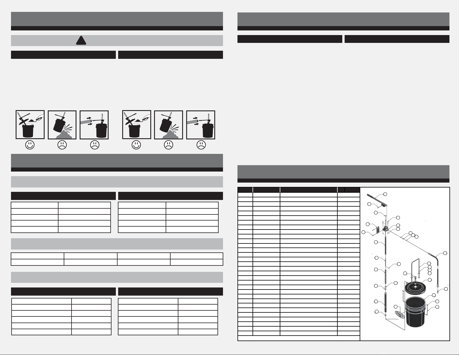
LISTA DE PARTES / PARTS
1 100-31-1 Sub palanca de 16” 1
2 H4-1 Remache semitub. AC 3/8” x 1-1/4” 1
3 K1-1 Oring 2-210 1/8”x 1-1/4” 1
4 F1-2-G Tornillo Hex. 1/4”-20 x 1” 1
5 100-32-CF Base para palanca 1
6 100-33 Tirante 1
7 H4-2 Remache semitub. AC. 3/8” x 1 - 1/2” 1
8 100-38-1 Vástago de 3/4” 1
9 100-36-2 Vástago de 3/8” 1
10 D-2 Chaveta AC. 3/32”x 3/4” 1
11 100-37-1 Casquillo de lámina 1
12 100-36-3 Triángulo guía 1
13 100-36-A Empaque válvula 1
14 100-35-E19 Sub. tubo cubeta 100 1
15 100-36-5 Pistón alimentador 1
16 C-75 Calcomanía ERKCO mediana 1
17 202-71257-E Tornillo “J” 1
18 104-Y89-8 Tuerca mariposa 1
19 113-65722-E Depósito de plástico 19 Lts 1
20 101-65B800 Tapa para depósito 1
21 A2-6-G Arandela helicoidal 3/8” 1
22 A1-6-G Arandela plana 3/8” 1
23 G1-3-G Tuerca hexagonal 3/8” 1
24 202-90272 Arco 1
25 101-73399-P Casquillo de polietileno 1
26 H3-025 Remache Rivkle Plus 1/4”-20 1
27 B-4 Bala diámetro 5/16”AC. Inoxidable 1
28 100-21-2 Resorte 1
29 ST-18 Anillo de retención Int. 7/16” 1
30 100-13 Sub Ensamble de manguera 1
31 100-31-1 SubVálvula de mordazas 1
*NOTA: El Kit de reparaciones es el K 100-100
LISTA DE PARTES / PARTS
ITEM No. DE PARTE DESCRIPCIÓN CANTIDAD
1 100-31 Sub palanca de 16” 1
2 H4-1 Remache semitub. AC 3/8” x 1-1/4” 1
3 K1-1 Oring 2-210 1/8”x 1-1/4” 1
4 F1-2-G Tornillo Hex. 1/4”-20 x 1” 4
5 100-32-CF Base para palanca 1
6 100-33 Tirante 1
7 H4-2 Remache semitub. AC. 3/8” x 1 - 1/2” 2
8 100-38-1 Vástago de 3/4” 1
9 100-36-2 Vástago de 3/8” 1
10 D-2 Chaveta AC. 3/32”x 3/4” 1
11 100-37-1 Casquillo de lámina 1
12 100-36-3 Triángulo guía 1
13 100-36-A Empaque válvula 1
14 100-35-E19 Sub. tubo cubeta 100 1
15 100-36-5 Pistón alimentador 1
16 C-75 Calcomanía ERKCO mediana 1
17 202-71257-E Tornillo “J” 2
18 104-Y89-8 Tuerca mariposa 2
19 113-65722-E Depósito de plástico 19 Lts 1
20 101-65B800 Tapa para depósito 1
21 A2-6-G Arandela helicoidal 3/8” 2
22 A1-6-G Arandela plana 3/8” 2
23 G1-3-G Tuerca hexagonal 3/8” 4
24 202-90272 Arco 1
25 101-73399-P Casquillo de polietileno 1
26 H3-025 Remache Rivkle Plus 1/4”-20 4
27 B-4 Bala diámetro 5/16”AC. Inoxidable 1
28 100-21-2 Resorte 1
29 ST-18 Anillo de retención Int. 7/16” 1
30 100-13 Sub Ensamble de manguera 1
31 100-31-1 SubVálvula de mordazas 1
*NOTA: El Kit de reparaciones es el K 100-100
1. Be sure that the grease used in this equipment is the one
specie (lithium 2 grade) and it´s clean and free of
waste.
2. Avoid hitting the tank on the oor. In case of air bubbles
forming around the piston feeder, push the grease down
with a tool.
3. Do not use a tube or shaft to increase the force on the
lever (see "Failure Analysis").
CHEVRON MOBIL SHELL MEXLUB
Multifak EP-2 Mobilux EP-2 Alvania Grease EP-2 Litio EP-2
Manual
19 Kg (42 Lbs)
210 Kg/cm² (3000 PSI )
11.1 cm (4.37”)
7 Kg (15.4 Lbs)
Type
Capacity
Maximum pressure
Piston stroke
Weight
Modo de operación Manual
Capacidad 19 Kg (42 Lbs)
Presión máxima 210 Kg/cm² (3000 PSI )
Carrera del émbolo 11.1 cm (4.37”)
Peso bruto 7 Kg (15.4 Lbs)
Altura con depósito 57.3 cm (26-1/2”)
Ancho total con depósito 50.8 cm (20”)
Longitud de la palanca 40.64 cm (16”)
Longitud de la manguera 130 cm (51-3/16”)
Puerto de salida 1/4”-18 NPT
Dimensiones del empaque 15.75”x 15.75” x 28”
Height with tank 57.3 cm (26-1/2”)
Width with tank 50.8 cm (20”)
Handle lenght 40.64 cm (16”)
Hose lenght 130 cm (51-3/16”)
Outlet diameter 1/4”-18 NPT
Seal dimensions 15.75”x 15.75”x 28”
1
2
3
5
4
6
7
8
9
10
11
13
14
15
16
12
26
27 28 29
30
31
17
18
19
20
21
22
23
24
25


