Ulvac Desktop YTP User manual

ひんやり感
Turbo-molecular-pump Pumping system
INSTRUCTION MANUAL
MODEL
Desktop YTP
YTP70A-D
Read this manual carefully and use the machine correctly.
Keep this manual with care so that you can refer at any time.
ULVAC INC, Components Division
YK18-0012-AI-101-02


i
YK18-0012-AI-101-02
Before Using the Machine
We thank you for purchasing a turbo-molecular-pump pumping system: Desktop YTP (hereinafter
referred to as "machine") of Ulvac, Inc.(hereinafter referred to as "We")
Upon receipt of the machine, please confirm the contents included are the same as you ordered
and check the machine for any damage attributed to transportation etc. just in case.
This operation manual (hereinafter referred to as "manual") describes appropriate operation and
maintenance methods in order to use the machine safely and effectively. Read this manual
beforehand and use the machine correctly.
Install and operate this machine according to the local and national safety laws and regulations
(such as fire laws and electric wiring code). Accordingly, you are required to take classes for
general safety that are valid in the country and the local area at the site. No one who hasn't take
the classes can handle the machine. The operator is required to have taken such trainings. In
addition, the operator has expertise, skills, qualifications in electrics, mechanics, cargo handling,
vacuum, etc.
This machine is designed to follow the current regulations as of the preparation of this manual. If
the criteria of the regulations are changed in the future, the compliance is not guaranteed.
If the device with this machine built-in doesn't follow the same regulations, or if any changes are
made to the machine itself, it may not be guaranteed to have its performance and safety. We
don't guarantee (have no responsibility for) such performance and safety. Any machine
modifications you have done are not covered by our warranty and we are not responsible for
them.
Before installing/removing this machine, keep the machine from all the energy sources (such as
electricity, cooling water etc.)
All the parts of this machine are not intended for permanent use with the performance at the
delivery. Even under the conditions of use expected in light of common sense, the performance
inevitably deteriorates with time, which tends to cause trouble on the machine. We would like to
ask you to grasp your conditions of use and cooperate to provide preventive maintenance to
avoid any trouble.
If you cooperate to make preventive maintenance measures, the likelihood of the trouble on this
machine attributed to malfunctions caused by worn parts will decrease and that of the risk, such
as downtime, fire, and influence on other processes, attributed to the trouble on this machine will
also decrease.
In addition, from the viewpoint of preventive maintenance, you are asked to prepare a
maintenance and inspection plan and conduct parts replacement and overhaul accordingly.
If you have any unclear points, please contact the closest sales office, agency, or our
Components Division.

ii
YK18-0012-AI-101-02
In this manual and warning signs on the machine, signal words and symbol marks are displayed
in order for you to understand the matters to adhere. The meanings are shown below:
▶ Meaning of signal words:
The terms that signify the warning level for safety are referred to as "signal words."
This indicates an imminently hazardous situation which, if the machine
is
misused, will result in operator's death or serious injury.
This indicates a potentially hazardous situation which, if the machine
is
misused, could result in operator's death or serious injury.
Signifies the possibility of suffering moderate degree of injury if the user
failed in handling.
Signifies important information about injury on human body.
▶ Meaning of symbol marks:
Signifies potential danger for injury on human body.
Signifies potential danger of electric shock.
Signifies potential danger of high temperature.
Signifies the matters "prohibited" or must not to do.
Signifies the matters "compulsory" or must to do.
Signifies that a protective gloves must be worn.
Signifies that a protective glasses must be worn.
Signifies that the instruction manual must be referred to.
About Safety Notation
Before Using the Machine
DANGER
WARNING
CAUTION
NOTE
S

iii
YK18-0012-AI-101-02
A warning label is attached onto a warning location on the machine. Never fail to check these
labels before operating the machine.
▶ Types and explanation on warning labels
Do not operate the machine while attaching a device that may interfere in the
passage of gasses on the exhaust
port side such as covering the port. This may
raise the pump
inner pressure which may end up in blowout of casing or level
gauge, oil leakage, or overload on the motor.
Explosive/Combustible/Flammable gas may ignite in the pump, increasing the
pump inner pressure. Do not exhaust any gas with these properties.
Be
fore using the machine, carefully read through the instruction manual until
understanding the details sufficiently.
Warning Label display position
Figure 1 Warning label pasting position
Types and display position on warning labels
Before Using the Machine

iv
YK18-0012-AI-101-02
This product is shipped after strict internal inspection. If you find any manufacturing defects,
accidents during the transportation, or other defects attributed to our responsibility, please contact
our Components Division at headquarters or the nearest sales office or agency. The
repair/replacement is free of charge.
▶ Warranty Product
(a) Turbo-molecular-pump pumping system Desktop YTP (YTP70 A-D)
▶ Warranty Period
(a) Domestic: 1 year from the date of delivery.
(b) Direct export: 1 year from the date of B/L.
▶ Warranty Coverage
(a) Domestic:
For a product at the time of delivery with a damage because of trouble during
transportation.
For a product not satisfying the basic specification in spite of using the product within the
service condition (temperature range, power supply, etc).
(b) Direct export:
For a product at the time of delivery with a damage because of trouble during
transportation.
However, for an international direct trade, it shall conform to the warranty coverage of
international merchandise trade condition (INCOTERMS etc) defined at the time of each
trade.
For a product not satisfying the basic specification in spite of using the product within the
service condition (temperature range, power supply, etc).
▶ How to Respond
(a) Domestic:
An alternative is delivered or the product is sent back to us or the nearest our ULVAC
TECHNO, Ltd. for repair.
If it is necessary to respond on site, contact our Components Division, or the nearest
sales office or agency for assistance.
(b) Direct export:
Return the product to our office or nearby service station. In response, we deliver a
replacement or repair the product.
The return expense shall be borne by the customer.
Warranty Clause
Before Using the Machine

v
YK18-0012-AI-101-02
▶ Disclaimer
(a) A product with expired warranty period
(b) Failures and defects caused by natural disasters including fire, wind and flood, earthquake
and thunderbolt, and unavoidable disasters including war.
(c) Failures and defects caused by careless handling or misuse.
(d) Products modified/disassembled/repaired without our permission.
(e) Failures and defects under an abnormal environment (strong electromagnetic field, radiation
environment, high temperature, high humidity, inflammable gas atmosphere, corrosive gas
atmosphere, dust).
(f) Failures and defects due to noise.
(g) Product failure or indirect damage to your company in the event of a claim by a third party to
us on violation of patents.
(h) When our engineers judge that the failures or defects are caused under the conditions of use
inappropriate to this product.
(i) Consumable articles
(j) A case in which a security seal is peeled off or a trace of peel-off is found.
▶ Others(Warranty Clause)
(a) If there are individual contracts and memorandum related to specifications in addition to this
document, the contents in those documents prevail.
(b) Please let us know if you export this machine from Japan and take necessary procedures
according to the provisions of export-related laws and regulations, such as foreign exchange
laws and foreign trade laws.
(c) For any questions and consultation on this machine, check the model/serial number and then
contact the nearest sales office or agency.
https://www.ulvac.co.jp/support_info/
(d) Note that the contents in this document is subject to change without prior notice.
● In order for you to use this machine as long as possible, before working on the installment,
operation, inspection or maintenance, read this manual carefully to fully understand the
safety considerations, specifications, and operation of the machine.
● Acknowledge in advance that, for improvement reason, the specification or price described
herein may be subject to change without notice. When a change is made in this manual, the
manual will be issued as a revised edition with the document number on the upper right of
the cover page updated.
● Never fail to hand over this manual to the end user who actually uses the product.
● Without our permission, any part in this manual cannot be duplicated for a third-party.
● This manual is designed for a Japanese speaking user. When allowing a non-Japanese
speaking user to work on the machine, provide a thorough safety education and handling
instruction under the responsibility of the customer.
About this manual
Before Using the Machine


Contents-1
YK18-0012-AI-001-01
Table of Contents
Before Using the Machine........................................................................ i
About Safety Notation ............................................................................................................ii
▶Meaning of signal words: ..........................................................................................ii
▶Meaning of symbol marks:........................................................................................ii
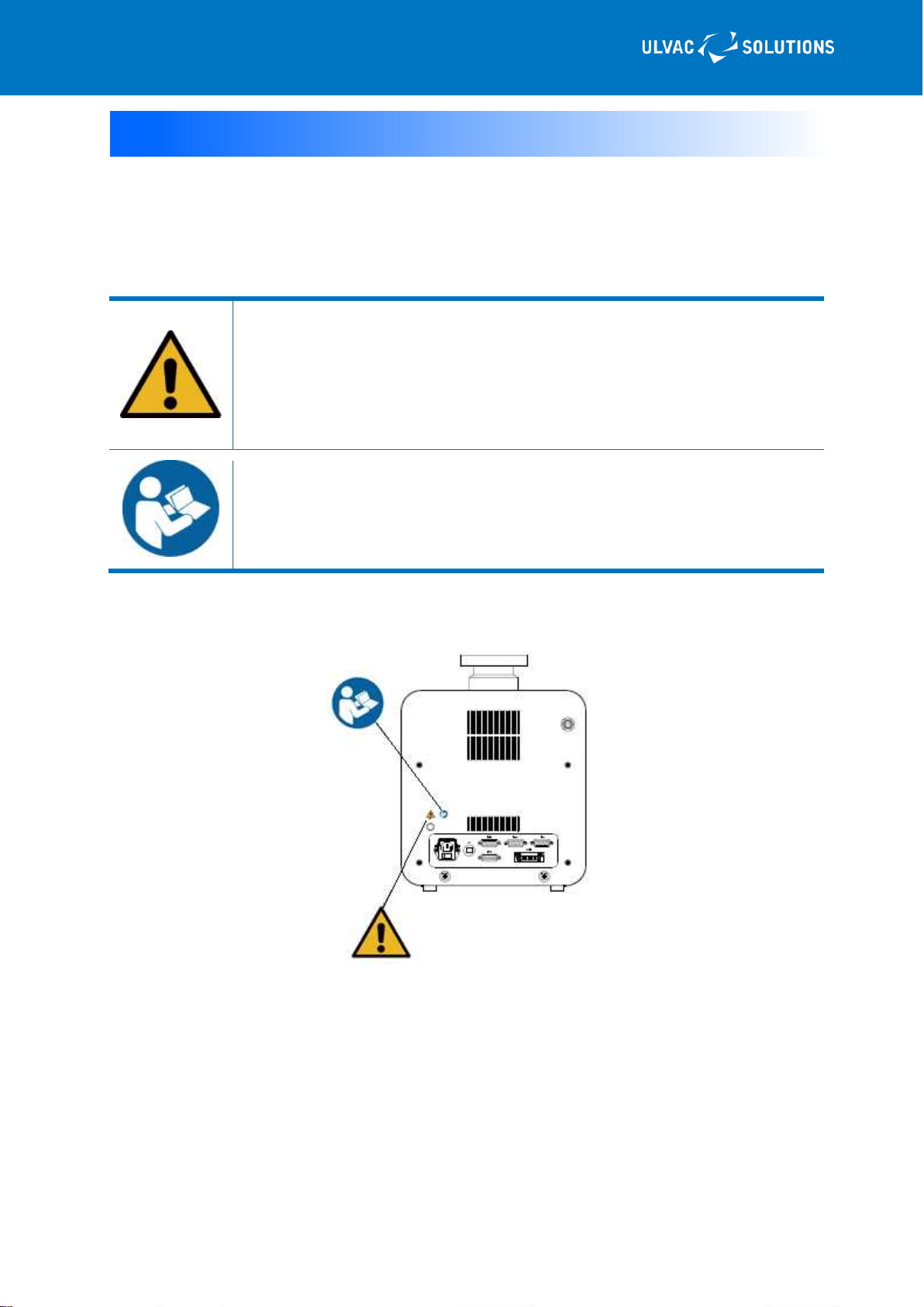
Types and display position on warning labels .......................................................................iii
▶Types and explanation on warning labels................................................................iii
Warranty Clause....................................................................................................................iv
▶Warranty Product .....................................................................................................iv
▶Warranty Period .......................................................................................................iv
▶Warranty Coverage..................................................................................................iv
▶How to Respond ......................................................................................................iv
▶Disclaimer .................................................................................................................v
▶Others(Warranty Clause).....................................................................................v
About this manual...................................................................................................................v
1. For safe use ........................................................................................1
1.1 Handling the machine...................................................................................................... 1
1.2 Acceptance /transport / storage ...................................................................................... 2
1.2.1 Acceptance............................................................................................................ 2
1.2.2 Transportation ....................................................................................................... 3
1.2.3 Storage.................................................................................................................. 3
1.3 Installation and operation ................................................................................................ 3
1.4 Disposal........................................................................................................................... 4
1.5 Protective equipment....................................................................................................... 4
1.6 Dangerousness inherent to the machine and safety measures...................................... 4
1.6.1 Intake and exhaust of dangerous gasses and substances................................... 4
1.6.2 Long-distance transportation ................................................................................ 5
1.6.3 Electric shock ........................................................................................................ 5
1.6.4 High temperature .................................................................................................. 5
1.6.5 Burst ...................................................................................................................... 6
2. Product Summary ...............................................................................7
2.1 Features .......................................................................................................................... 7
2.2 Use .................................................................................................................................. 7
2.3 Names and works on each section ................................................................................. 8
2.4 Explanation on touch panel operation screen ............................................................... 10
2.4.1 Initial screen ........................................................................................................ 10
2.4.2 Main screen......................................................................................................... 10
2.4.3 VAC screen ..........................................................................................................11
2.4.4 Menu screen ....................................................................................................... 12
2.4.5 Delay timer setting screen................................................................................... 12
2.4.6 P1 setting screen ................................................................................................ 13
2.4.7 P2 setting screen ................................................................................................ 13
2.4.8 etc.1/etc.2 screen ............................................................................................. 14
2.4.9 FIL screen ........................................................................................................... 16
2.4.10 DEG screen....................................................................................................... 16
Table of Contents

Contents-2
YO18-0012-AI-101-01
2.4.11 Alarm pop-up screen ......................................................................................... 17
2.4.12 Numeric key screen .......................................................................................... 17
3. Installation.........................................................................................18
3.1 Before installation.......................................................................................................... 18
3.1.1 Works from shipment to startup .......................................................................... 18
3.1.2 Environmental condition for storage ................................................................... 19
3.1.3 Environmental condition for installation and operation ....................................... 19
3.2 Unpacking...................................................................................................................... 20
3.2.1 Cautions on unpacking........................................................................................ 20
3.2.2 Check following to unpacking ............................................................................. 20
3.3 Transport ....................................................................................................................... 22
3.3.1 Transportation by pallet truck .............................................................................. 22
3.4 Piping and wiring ........................................................................................................... 23
3.4.1 Intake and exhaust piping ................................................................................... 22
3.4.2 Gas purge .......................................................................................................... 24
3.5 Electric wiring ................................................................................................................ 25
3.5.1 Electric wiring ...................................................................................................... 25
4. Operation ..........................................................................................26
4.1 Cautions on operation ................................................................................................... 26
4.2 Preparation for operation ............................................................................................. 27
4.2.1 Check items before operation ............................................................................. 27
4.3 Startup and stop operation method ............................................................................... 28
4.3.1 Startup and stop.................................................................................................. 28
4.3.2 External interlock................................................................................................. 29
4.4 Connecting G-TRAN ..................................................................................................... 30
4.4.1 Setting of G-TRAN .............................................................................................. 30
5. Maintenance and Inspection .............................................................36
5.1 Daily inspection ............................................................................................................. 36
5.2 Inspection after prolonged storage................................................................................ 36
5.3 Overhaul ........................................................................................................................ 36
6. Troubleshooting.................................................................................37
6.1 Problem in basic motion ................................................................................................ 37
6.2 Alarm state and the responding action ........................................................................ 38
6.3 Re-start after alarm generation ..................................................................................... 39
7. Specification ....................................................................................40
7.1 Performance specification ............................................................................................. 40
7.2 External dimensional drawing ....................................................................................... 41
Appendix
Main replacement parts

1
YK18-0012-AI-101-02
1. For safe use
Signifies, by each work, the method for avoiding danger and the actions prohibited to do for
dangerousness reasons.
1.1 Handling the machine
For an overhaul, repair, or problem on the machine, contact a neighboring service center.
Inert gasses (air, nitrogen, and argon) can be discharged with this machine.
Other gasses (toxic, combustion, combustion-
supporting, corrosive, and
explosive gases) cannot be used since they may be leaked from the pump
main unit, or ignition or explosion may be occurred inside the pump when
discharged.
Install the machine in a ventilated indoor room.
If nitrogen or argon is leaked, you may be suffocated because of deficiency in
oxygen.
Before working on the installment or removal, keep the machine away from all
of the energy sources (power supply, cooling water, etc)
If this machine sucks
in a toxic gas, not only the pump main unit but also the
lubricating oil may become poisonous. Be careful to this at the time of
maintenance work.
Install an appropriate filter separator trap so as not let the machine sucks in
liquid and solid particulates.
● This machine is designed so as to conform to the rules and regulations at the time of preparing
this manual. The conformity to the rules and regulations shall not be necessarily guaranteed if
the standard of rules and regulations are changed in future.
● If a device embedded in this machine does not conform to the same rules and regulations or if
the machine itself is modified, the performance and the safety of the machine may not be
guaranteed. In such a case, we can neither guarantee the performance and the safety nor take
the responsibility.
● For those who never took general safety education which is regarded to be effective publicly in
the country intended to use, by any means, do not use the machine. An operator shall receive
such trainings.
● Install and operate the machine according to the rules, regulations, and ordinances (Fire
Service Laws and electric wire regulations) on safety of the country intended to use
DANGER
DANGER
DANGER
DANGER
NOTE
S

2
YK18-0012-AI-101-02
● If the details of dangerous substances to be used is not disclosed, or the substances difficult to
undergo a detoxication processing are discharged, we may reject the maintenance and other
related handlings.
If you entrust us of an overhaul, maintenance, or repair etc, enter the necessary information in
the "Pollution Certificate" attached to the end of this manual and submit it to a service center.
● If you export this machine to the outside Japan, you are required to pass through several
examinations based on the foreign exchange and foreign trade laws, and the related
government and ministerial ordinances and notifications etc. Contact a nearby sales office or
agent.
【Sales offices list】
https://www.ulvac.co.jp/support_info/sales_office/
1.2 Acceptance /transport / storage
1.2.1 Acceptance
Do not enter the underside of the machine.
If the ma
chine is operated recklessly, or the maintenance is insufficient, the
machine may be fell off or toppled down. Do not enter the underside of the
machine.
Only a qualified person shall perform a cargo-work and operate a cargo-
handling machine.
An unqualified person shall neither perform a cargo-work nor operate a cargo-
handling machine.
Upon unpacking, check that there are no missing or damaged components.
After unpacking, check that there are no missing, damaged, or abnormal
components. If there
is a problem by any chance, do not work on the installation
work.
▶ For safe use
NOTE
S
DANGER
WARNING

3
YK18-0012-AI-101-02
1.2.2 Transportation
For a long-distance transportation, the machine shall be carried by a cargo-
handling device or by a pallet truck.
If the machine is transferred for a long distance f
or such reasons as changing
the room to install etc, you may suffer a backache or get injured. For long
distance transportation, fix the machine on a cart or a pallet, and use a pallet
truck.
Attach a transportation jig for transportation.
Never fail
to attach a transportation jig when transferring the machine. Without
attaching the transportation jig, the machine may possibly be damaged during
the transportation.
1.2.3 Storage
Keeping the environmental conditions
This machine includes precise clearanc
es. Check that the storage place
satisfies "3.1.2 Environmental condition for storage."
1.3 Installation and operation
Do not detach the face panel
Do not detach the face panel. There is a possibility of getting burned or electric
shock.
Do not h
ave the machine impacted, tilted, toppled sideways, stood upright, or
made upside-down.
Do not have the machine impacted, tilted, toppled sideways, stood upright, or
made upside-down.
The operation of the machine may be obstructed. Horizontally install the
machine.
Do not start operation of the machine until the main unit of the machine
reaches the operational temperature range.
If the machine is stored at a place outside the operational temperature range,
do not start operation of the machine until th
e main unit temperature reaches
the operational temperature range.
NOTE
S
NOTE
S
NOTE
S
NOTE
S
WARNING
WARNING

4
YK18-0012-AI-101-02
Horizontally install the main unit of the machine
If you have the machine tilted, toppled sideways or made upside-
down, the
machine may be damaged. Horizontally install the machine with the intake
port
facing upward.
Keeping the environmental conditions
This machine includes precise clearances. Check that the installation place
satisfies "3.1.3 Environmental condition for installation and operation
1.4 Disposal
Especially
after the exhaust of hazardous gas on a human body, please ask a
professional company to dispose of the pump.
For the disposal of machine that discharged gasses harmful to humans,
entrust a specialized processor.
Dispose the machine following to the national laws and local government ordinances.
Especially, if harmful gasses are discharged, entrust a specialized processor to do the disposing and
processing works.
The cost for the disposal shall be borne by the customer.
1.5 Protective equipment
Never fail to attach an earth leakage breaker.
Without an earth leakage breaker attached, the machine may be burned, or a
fire or electric shock may be break out.
The machine is not equipped with a mechanism for interrupting the motive power and a function for
detecting an electric leakage.
For choosing an electric leakage breaker, refer to the "electric wiring."
1.6 Dangerousness inherent to the machine and safety
measures
1.6.1 Intake and exhaust of dangerous gasses and substances
Do not discharge toxic gasses, combustion gasses, combustion-supporting
gasses, corrosive gasses, and explosive gasses.
Discharging toxic gases, combustion gases, combustion-supporting gases,
corrosive gases, and explosive gasses is extremely danger.
Moreover, it would be extremely danger if such gasses are sucked in the
machine, because, not only during the operation but also after stopping, the
residue gasses or generated substances may cause fire or explosion.
▶ For safe use
NOTE
S
NOTE
S
DANGER
WARNING
WARNING

5
YK18-0012-AI-101-02
Wearing protective gears
When doing an inspection or other works, wear a protective gear suitable for
the poisonous substance to use.
Entrusting a waste disposer for disposal.
Entrust a waste disposer authorized by the administration for disposal works.
Entrust a specialized processor for detoxication processing.
For an overhaul or disposal, entrust a processor specialized in waste disposal
to do the detoxication processing.
1.6.2 Long-distance transportation
An unqualified person shall neither perform a cargo-work nor operate a
cargo-handling machine.
An unqualified person shall neither perform a cargo-work nor operate a
cargo-handling machine.
Ignorance to this may cause an accident or injury.
1.6.3 Electric shock
Before working on an electric wire connection, turn off the primary power
supply.
Before working on an electric wire connection, never fail to turn off the
primary power supply.
For an inspection or relocation, turn off the primary side power supply.
For an inspection or relocation, never fail to turn off the primary side power
supply.
Never fail to connect an earth terminal to the ground.
An electric work specialist qualification is required for such engineering
works as burying an earth and connecting earth wires. Imperfectly
connected earth wires may cause an electric shock.
1.6.4 High temperature
Do not detach the face panel
Do not detach the face panel. The machine holds extremely high temperature
during the operation which persists for a while even after stopping. You may
get burned by touching the machine.
DANGER
DANGER
DANGER
WARNING
WARNING
WARNING
WARNING
WARNING

6
YK18-0012-AI-101-02
1.6.5 Burst
Do not set 0.03 MPaG or more for the exhaust side pressure of the machine.
Measure the pressure on the pump exhaust side and if it is 0.03 MPaG (0.3
kg/cm2G) (gauge pressure) or more, remove the obstacle that blocks the
passage of the gas on the exhaust side.
If the pump internal pressure raises to 0.03 MPaG or more, the pump may be
burst.
▶ For safe use
WARNING

7
YK18-0012-AI-101-02
2. Product Summary
Desktop YTP is a desktop type high vacuum pumping system equipped with a ceramic ball-bearing
type turbo-molecular pump. In consideration of desktop operating environment, the noise and
vibration during the operation have been reduced. Moreover, a newly employed touch panel with
intelligible display icons enables simple operation.
2.1 Features
■Designed for desktop operating environment
● The noises and vibrations on operation are reduced.
■ Low noises
● Low noise with 43dB (A) or less during operation.
(Operation without load. ICF flange type. Measured by us)
■Compact and light-weight design
■Excellent operationality
● Simple operation with a touch panel.
■A dedicated display for vacuum gauge is not necessary
● Vacuum gauge signals can be imported to display on the operation screen.
● Maximum two units of vacuum gauge can be connected (a vacuum gauge is an option).
2.2 Use
Do not use the machine for the purpose other than described herein.
Using the machine for the purpose other than described herein may cause an
unexpected accident or breakdown.
● High-vacuum system for various experiments and researches.
● High-vacuum system from atmospheric pressure.
● Whole other high-vacuum exhaust purposes.
WARNING

8
YK18-0012-AI-101-02
2.3 Names and works on each section
Figure 2 Name of each part
Table 1 Name of each part
Name Description
1 Intake port Containers or piping for vacuum exhaust are connected.
2 Exhaust port The piping for discharging the exhausted gasses is connected.
3 Handle It is a handle for placing your hand to lift up the product.
4 Touch panel Status of operation, stopping, or alarm is indicated.
5 Connector panel It is used for power supply connection, switch operation, and external
device connection.
6 Gas purge unit interface It is an interface with the gas purge unit (option),
7 Transportation jig It is a jig (bolt) for fixing the FP to protect the device during
transportation.
①
②
③
④
⑤
⑥
⑦

9
YK18-0012-AI-101-02
Figure 3 Name of the connector panel
Table 2 Name of the connector panel
Name Description
1 AC INPUT connector It is the primary side power supply input section of the main unit of
the machine.
2 MAIN POWER switch It is the main power supply switch.
3 Circuit protector Shuts down the power supply when the main power supply is
overloaded.
4 D-IG connector
It is an ionization vacuum-gauge import connector.
Supports following G-TRAN models.
ST2-1、SH2-1、SC1
5 D-PG connector
It is a low-vacuum area vacuum-gauge import connector.
Supports following G-TRAN models.
SW1-1, SP1
6 D-CC
It is a capacitance manometer import connector.
Supports following G-TRAN models.
CCMT-D
7 CNSIL
It is a device operation signal input connector. Following operations
are performed.
Input of START interlock signal.
Input of ionization vacuum gauge filament FIL1/FIL/2 switchover.
◆Arrange a non-voltage contact for the input signals.
8 D-TMP
Histories etc can be checked by connecting to TMP via RS485
communication using the I/F cable and communication cable for
UTM70B. For more details, refer to TMP instruction manual.
▶ Product summary
D-PG
D-CC D-TMPD-IG
CNSIL
AC-IN
CP
1 2 3 4 5 6

10
YK18-0012-AI-101-02
2.4 Explanation on touch panel operation screen
2.4.1 Initial screen
Turning on the power supply switch displays the initial screen.
After passing a few seconds, the operation main screen is switched to appear automatically.
Figure 4 Initial screen
Table 3 Explanation of initial screen
Name Description
1 Display of version
information The software version is indicated.
2.4.2 Main screen
It is an operation screen for devices.
The devices can be started up or stopped by operating the switches.
Figure 5 Main screen
Table 4 Explanation of main screen switch
Name Description Turning on
light Blinking Turning off
light
1 VAC switch
Operation for starting
up and stopping of the
machine
A high-vacuum
Pumping is
running
Starting-up/
Stopping
Completion
of stopping
2 MENU switch Setting for each
device -
3 FIL switch※1
Filament operation at
the time of using the
ionization vacuum
gauge
Turning ON
the filament - Turning OFF
the filament
4 DEG switch※1
Degassing operation
at the time of using the
ionization vacuum
gauge
Turning ON
the degassing -
Turning OFF
the
degassing
※1:Displayed only when setting P1.
▶ Product summary
①
①
②
①
③
⑥
⑦
④
⑤
This manual suits for next models
1
Table of contents
Other Ulvac Water Pump manuals

Ulvac
Ulvac CRYO-U Series User manual

Ulvac
Ulvac ULK-04A User manual

Ulvac
Ulvac DTC-41 User manual

Ulvac
Ulvac DOP-80SP User manual

Ulvac
Ulvac PVD-180 User manual

Ulvac
Ulvac DOP-120SX User manual

Ulvac
Ulvac DAL-181D User manual

Ulvac
Ulvac CRYOPUMP CRYO-U Series User manual

Ulvac
Ulvac DA-121D Series User manual

Ulvac
Ulvac UTM1600 Series User manual

Ulvac
Ulvac DOP-181S Series User manual

Ulvac
Ulvac CRYO-U Series User manual

Ulvac
Ulvac VS1501 User manual

Ulvac
Ulvac DTU-20 Series User manual

Ulvac
Ulvac VD30C User manual

Ulvac
Ulvac TM-2 User manual

Ulvac
Ulvac CRYO-U12H User manual

Ulvac
Ulvac GLD-137CC User manual

Ulvac
Ulvac DOP-40D User manual

Ulvac
Ulvac CRYO-U Series User manual