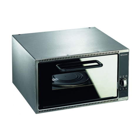
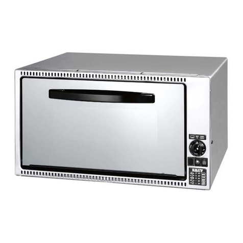
Dometic Cramer CMBOK Operation and maintenance manual

Part No. 44836
Instructions of operation and installation
for
mini-ovens CRAMER
Model CMBO
Variants: CMBOK, CMBOA, CMBOC, CMBOB
CMBOD, CMBODS, CMBODSV
CMBOGDS, CMBOGDSV
GB
GB, IE, IS
Identification No. of product
CE-1015BP0202

2
Important warnings
This device as an appliance of the 3rd class is intended to be built into a kitchen block.
Oven output (Hs) 1,1 kW (Mn = 80 g/h, propane/butane)
Grill output (Hs) 1,6 kW (Mn = 115 g/h, propane/butane)
(It is ensured and technically impossible that the two burners be turned on at the same
time.)
In case the gas tap may be hardly turned or if it gets jammed, it should be either replaced or the
respective cone of valve should be detached from the valve, cleaned by benzine and lubricated
with special grease for taps, e.g. from the company Klüber, Munich, type „Staburgas No. 32“,
and attached back. This act should be carried out only by an expert in gas appliances.
Installation of the facility may be carried out only by expert workers with appropriate
certificate!
This facility should be installed and connected according to applicable conditions of installation
as EN 1949. Special care should be paid to determined measures regarding aeration.
Before connecting the oven, it is necessary to check whether the local conditions for connections
(type of gas and gas pressure) are identical with the setting of the appliance. The type of gas and
the gas pressure for this appliance are indicated on the instruction plate (or the product's name
plate).
Before being put into operation as well as after each 2 years, the parts conducting gas and
connected exhaustion of waste gases (gas exhaust pipe) should be checked by an expert
according to applicable standards, especially to European Standard EN 1949.
The user is responsible for ensuring the check. The expert performing the installation of the oven
shall notify him/her of the obligation of check in writing.
The appliance may only be used for the purposes of baking and grilling and under the conditions
specified below. It may be in no case used for other purposes than described in these operating
instructions (e.g. for heating etc.).
The use of the oven may lead to a generation of heat and moisture at the place of installation.
Take care of good aeration of the kitchen: natural aeration openings should be clear or, as the
case may be, it is necessary to provide for a mechanical venting device.
Intense and long-term using of the oven may require additional venting, e.g. opening of the
window or operating of a mechanical venting device on a higher performance level.
The pressure reduction (regulator) used between the gas cylinder and the oven should be of
output 1.5 kg/h:
3
ATTENTION: ACCORDING TO APPLICABLE STANDARDS, THE DEVICE SHOULD
BE INSTALLED BY AN EXPERT.
IMPORTANT: TO AVOID ANY POSSIBLE ACCIDENT, IT IS NECESSARY TO
INSTALL THE DEVICE ACCORDING TO THESE INSTRUCTIONS. LOSS OF
WARRANTY IS A CONSEQUENCE OF INEXPERT INSTALLATION
„ANY MODIFICATION TO THE APPLIANCE MAY BE DANGEROUS, AND IS
THEREFORE NOT PERMITTED !“
1. AERATION OF THE ROOM
Every room where one or more appliances are to be installed must have one or more openings
to allow the entry of fresh air. Above the appliance there have to be one or several openings in
order to assure the exhaust of combustion and renewal of fresh air.
These ventilation openings must comply with the requirements of EN 1646-1, EN 1949 and
EN 721.
These openings need to be checked from time to time. If necessary, the user should clean them
(e.g., in wintertime, snow or dirt should be removed from the exhaust output and the
combustion air input).
If the appliance is built-in, safety regulations must be observed, and particularly the European
standard EN 1949.
Outlets of waste gases may not be installed at entrance doors and below aeration openings.
When exhaust gases are discharged, the ascending position of all parts needs to be
checked.
2. CONNECTION OF THE OVEN TO THE GAS SUPPLY
The connection of gas to the oven may be carried out exclusively with gas-tight connections.
Tubes used to connect the oven should be of zinc-coated iron or copper. These pipes may be
used only with gas-tight connection. Having finished connection works, it is necessary to
check tightness of the connection, using soap solution that is poured on the connection. Soap
solution shows possible leakages by creating bubbles.
ATTENTION: WHEN INSTALLING AND CONNECTING THE DEVICE, THE GAS
PIPELINE MAY NOT BE TWISTED, PULLED, NOR OTHERWISEE STRAINED.

4
3. GAS CYLINDERS
It is necessary to use such gas cylinders that are usually sold in the country of sale of the
appliance. Kind of gas used is clearly indicated on the packaging and on an indelible type
plate on the rear side of the oven.
UNSUITABLE OPERATION CONDITIONS OF THE FACILITY MAY BE A
CONSEQUENCE OF USING ANOTHER PRESSURE OR GAS THAN STATED IN
THE INSTRUCTIONS. THEREFORE THE MANUFACTURER DECLINES ANY
LIABILITY IN CONNECTION WITH INEXPERT OPERATION OF THE
APPLIANCE.
In any case, the following instructions shall be adhered to:
Complete gas cylinders with a valve and pressure reduction (regulator) should be placed in
vertical position in a cabinet exclusively intended for that purpose. Access to cylinders must
not be obstructed.
Replacement of gas cylinder should be simple, while it should be possible to carry it out
without any obstacles.
BE SURE TO SHUT THE GAS CYLINDER VALVE AFTER USE.
ATTENTION!
The following safety precautions should be adhered to, when replacing the gas cylinder:
a) close taps of the device (revolving button in the position „0)“;
b) shut the gas tap in the vehicle that is assigned to the appliance.
c) make sure there were no open flames or glowing objects around;
d) close the valve of the cylinder being replaced;
e) detach the pressure reduction (regulator) of the empty gas cylinder, take the gas
cylinder out of the cabinet and replace it with a new one –carry out connection of the
new cylinder in the reverse sequence.
f) dheck tightness, using soap solution, as explained above.
g) Ignite the burner and check whether the oven works properly. If it does not, contact a
specialised engineer.
3.1 CABINET FOR GAS CYLINDERS
A cabinet for gas cylinders should be sufficiently large to accommodate the shown type of
gas cylinder with pressure regulator attached. In Germany, its width and depth may not be
smaller than 325 mm and the height less than 620 mm.

5
4. VISUAL INSPECTION OF FLAME
a) The flame should burn quietly. It should be prevailingly blue, having clear outlines.
b) When the flame is not burning cleanly, there should be checked, whether openings of air
inlet (Venturi tube) are clear. If it is not the case, particles causing obstruction should be
removed.
c) In case of any doubt a gas specialist needs to be consulted.
5. POWER SUPPLY AND ELECTRICAL CONNECTION:
The appliance needs 12 V DC power supply for possible future internal lighting and
electronic stroke spark ignition. For special "Z" models, the stroke spark ignition will be
initiated by a replaceable 1,5 V battery.
ELECTRICAL CONNECTION
To connect the facility, a twin cable of 1.5 mm2with red and black colours should be used,
which shall be connected to the terminal placed on the rear side of the device. The poles on
this terminal are indicated + and –. You will recognise the positive pole by red colour. When
connecting the cable, in any case take care of correct poling! Electrical circuit should be fused
with 3 A safety fuse (not delivered with the device).
IN NO CASE THE DEVICE MAY BE CONNECTED TO 230 V MAINS SUPPLY!
THIS WOULD LEAD TO DEFINITE DESTRUCTION OF ELECTRIC PARTS AND
IT WOULD BE ASSOCIATED WITH A HAZARD TO THE CUSTOMER.
6. LEAKAGE OF GAS
When testing leakages of gas, we recommend you to use an electronic gas leak detector with
type approval. In case of a defect, the tap of gas supply must be closed. Contact a gas fitter,
dealer or specialised engineer.

6
7. INSTALLATION OF THE DEVICE
7.1 ATTACHMENT OF THE DEVICE TO FURNITURE
In order to install the device, there should be created a space of dimensions shown in Figure 1
depending on the respective model of device (look at type plate of the device).
Figure 1
Variant X (Width) Y (Depth) Z (Height)
CMBOK 398 490 284
CMBOA 398 490 304
CMBOC 484 490 284
CMBOB 484 490 304
CMBODS 524 490 354
CMBODSV 524 490 354
CMBOGDS 524 490 354
CMBOGDSV 524 490 354
At installation of oven with exhaust of waste gases at the back the depth will be elongated to
550 mm.
The position of this space may be selected depending on the intended point of installation.
Within the built-in furniture, the oven should be placed on a firm, stable platform. The oven
should be fixed on the front side of the built-in furniture, using the attached 4 screws (Figure
2). Gas pipings, taps or parts of burner may not be used for fixing.

7
Minimum distance from inflammable surfaces on the right and left sides: 20 mm. Minimum
distance from inflammable upper surfaces: 50 mm. Minimum distance of the waste gas
exhaust case from inflammable surfaces: 50 mm.
All walls or constituent parts that are at a smaller than minimum distance from the appliance
should be either lined or protected with non-flammable materials.
Figure 2
Figure 3
Installation of oven with gas exhaust pipe upward through roof chimney.

8
Roof chimney Truma, art.No. 30700-03
atr. No. 39320-00
Ventilation chimney tube Truma O55
Exhaust box
Figure 4
Installation of oven with exhaust of waste gases upward through a chimney across the wall.
Chimney across the wall Truma, art.No. 34011-08
Ventilation chimney tube Truma O55
atr. No. 39320-00
Exhaust box
Figure 5
Installation of oven without a chimney exhausting waste gases through front of appliance.

9
Exhaust box

10
Figure 6
Installation of oven with gas exhaust pipe at the back through roof chimney.
Ventilation chimney tube Truma O55
Roof chimney Truma, art.No. 30700-03
atr. No. 39320-00
Exhaust box
Figure 7
Installation of oven with exhaust of waste gases at the back through a chimney across the wall.
Chimney across the wall Truma, art.No. 34011-08
Ventilation chimney tube Truma O55
atr. No. 39320-00
Exhaust box

11
Exhaust of waste gases through the chimney should be of continuously ascending placing.
Maximum length of waste gas outlet is 2,000 mm. The maximum difference of height between
the upper edge of the oven for baking and the outlet of waste gases is 1,500 mm. For ducting the
exhaust gases over a side wall stack, the minimum elevation difference is 150 mm, and 200 mm
for a Truma roof stack.
Walls and integral parts whose distance from waste gas exhaust pipe is less than 50 mm should
be either lined or protected with materials belonging to the group of fire resistance M0.
At the output from the oven and at the input to the stack extension, the exhaust from the flexible
metallic pipe with a diameter of ∅55 mm must be attached with a worm hose clamp (a Truma
clamp is convenient for the given ∅50 – ∅60 mm pipe), or with the attachment screw supplied
along with the Truma roof stack.
THE DEVICE SHOULD BE PLACED OUT OF REACH OF EASILY INFLAMMABLE
MATERIALS.
7.2 PROTECTION FROM OVERHEATING
All conditions for installation of the facility described under the point 7.1. are necessary to be
adhered to.
7.3 TAKING THE DEVICE OUT OF FURNITURE
a) Close the main gas valve.
b) Loosen fixing screws.
c) Loosen gas connection and possible electrical cables.
8. USE THE DEVICE ONLY IN A WELL AERATED ROOM
During operation of the appliance, the aeration openings have to be clear.
9. USING THE OVEN
ATTENTION: please push up the lock handle with thumb to open the door. At shutting of the
door the handle locks door automatically.
9.1 IGNITION OF THE OVEN
The oven is equipped with an electronic stroke spark ignition system.
a) To light the oven or the grill, the door of the oven must be fully open.
b) Press the turn button lightly and turn it to the left to the ignition position. The oven may
be lit at any position of the turn button. After igniting flame, still hold the button pressed
for the time of about 10 seconds. The lighting of the grill (for an oven with grill) can be

12
done with the turn button at its "Grill" position (the button turned to the right after
pressing).
c) Release the button and turn it to the desired position.
The oven is equipped with an automatic thermostat.
Various settings of the revolving button correspond to temperatures within the range up to 250
oC.
In case of an excessive deviation of temperature of the oven, the thermostat should be
repaired.
IMPORTANT: In case ignition does not succeed, repeat the procedure from the beginning. If
necessary, you should check, whether gas supply is not missing in the device or, as the case
may be, electric power. If the device would not work despite that, close the tap of gas inlet
and contact your dealer. Before putting into operation for the first time the oven should be left
baking idle (without any foodstuffs) for the time of approximately ½ an hour at the highest
temperature. In case the burner goes out unintentionally, turn off the knob and, before turning
on again, let the burner be switched off for the time of 1 minute at least.
„GLOVES ARE NECESSARY TO BE USED UPON HANDLING HOT OBJECTS.“
9.2. OPERATION OF OVEN
a) The pan should be pushed in the guiding rail.
b) The position of pan may be chosen out of three vertical positions.
ATTENTION: When being used, the oven attains high temperatures. Avoid
presence of children in its vicinity.
9.3 OPERATION OF GRILL (for appliances with the grill function only)
a) Light the grill burner with the door fully open.
b) When grilling, the door of the oven must be open.
ATTENTION: When being used, the oven attains high temperatures. Avoid
presence of children in its vicinity.
10. FAULTS OF THE FACILITY
Upon faults of the facility, contact a specialised expert.

13
INSTRUCTIONS FOR CLEANING
Exclusively non-aggressive cleaning agents for households may be used for cleaning. In no
case, agents for scrubbing and bleaching may be used.

14
DOMETIC CRAMER SR s. r. o.
●Tehelná 8 ●SK – 986 01 Fiľakovo ●Phone: +421-47 4319100 ●
●Fax: +421-47 4319144, 4319166 ●
●E-mail: [email protected] ●
●Internet: www.cramer.sk ●www.dometic.com ●
This manual suits for next models
8
Table of contents
Other Dometic Oven manuals

Dometic
Dometic OG2000 Installation and operating instructions

Dometic
Dometic miniCool DS 300 User manual

Dometic
Dometic FO200FT Specification sheet

Dometic
Dometic OVG340I Quick start guide

Dometic
Dometic RKE 400 Quick start guide

Dometic
Dometic StarLight User manual

Dometic
Dometic OVN0250 User manual

Dometic
Dometic FO250SA User guide

Dometic
Dometic FO611C070000000 User manual
Popular Oven manuals by other brands

AEG
AEG COMPETENCE KB9820E brochure

Miele
Miele DGC 7660 Operating and installation instructions

Frigidaire
Frigidaire FGET2765KF - 27" Double Electric Wall Oven Brochure & specs

Salini
Salini SOD-8002H instruction manual

Whirlpool
Whirlpool W9 OS2 4S1 P manual

Garland
Garland moisture+ MP-GD-10-S Service manual