Dometic WH-6GEA User manual

HEATING
WATER HEATERS
Form No. 3317866.000 04/21 | ©2021 Dometic Corporation
WARNING
Cancer and Reproductive Harm
www.P65Warnings.ca.gov
WH - 6GA, WH - 6GEA, WH - 9GEA, WH - 10GEA, WH - 16GEA
EN L.P. Gas Water Heater
Installation and Operation Manual........2
FR Chauffe-eau à gaz P.L.
Manuel d’installation et d’utilisation .... 25
WARNING: If the information in this
manual is not followed exactly, a fire or
explosion may result, causing property
damage, personal injury, or death.
– Do not store or use gasoline or other
flammable vapors and liquids in the
vicinity of this or any other appliance.
– WHAT TO DO IF YOU SMELL GAS
• Evacuate all persons from the vehicle.
• Shut off gas supply at the gas
container or source.
• Do not touch any electrical switch, or
use any phone or radio in the vehicle.
• Do not start the vehicle’s engine or
electric generator.
• Contact the nearest gas supplier
or qualified service technician for
repairs.
• If you cannot reach a gas supplier or
qualified service technician, contact
the nearest fire department.
• Do not turn on the gas supply until the
gas leak(s) has been repaired.
– Installation and service must be
performed by a qualified installer, service
agency or the gas supplier.
WARNING: BURN HAZARD, FIRE,
EXPLOSION, AND/OR CARBON MONOXIDE
HAZARD.
Keep the water heater area clear of combustible
cleaning materials, gasoline, and other flammable
vapors and liquids. Failure to obey this warning
could result in death or serious injury.
WARNING.
This product can expose you to lead, which is
known to the state of California to cause cancer and
birth defects or other reproductive harm. For more
information, go to www.P65warnings.ca.gov.

2EN
Contents L.P. Gas Water Heater
1 Explanation of Symbols and Safety
Instructions ............................ 2
1.1 Recognize Safety Information .............2
1.2 Understand Signal Words................2
1.3 Supplemental Directives.................3
1.4 General Safety Messages ................3
2 Intended Use ........................... 3
3 General Information ..................... 4
3.1 Tools and Materials .....................4
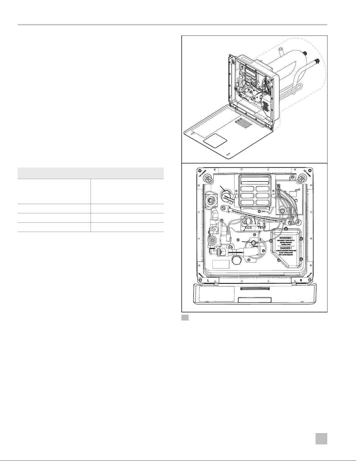
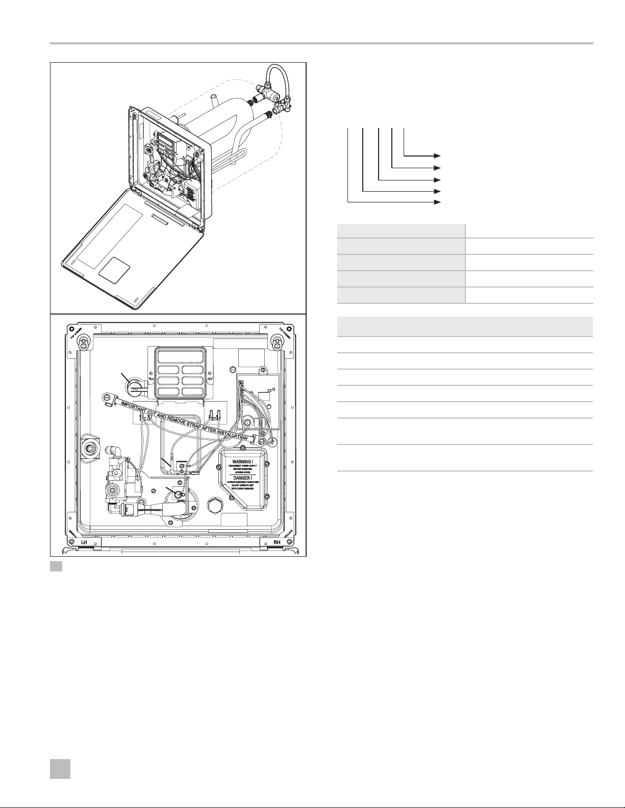
3.2 Component Locations. . . . . . . . . . . . . . . . . . .4
3.3 Model Identification ....................5
3.4 Unit Specifications......................6
4 Installation............................. 6
4.1 Preparing the Installation Location .........7
4.2 Blocking the Water Heater ...............8
4.3 Installing the Water Hose ................8
4.4 Installing The Gas Line...................9
4.5 Installing The Control Switch .............9
4.6 Wiring the 115 VAC Power Supply ........10
4.7 Installing The Unit .....................12
4.8 Installing The Access Door ..............14
4.9 Performing Leak Testing ................14
5 Operation............................. 14
5.1 Operating the Electronic Control.........15
5.2 Clearing a Water Heater Operation Failure . 16
5.3 Shutting Down the Water Heater .........16
6 Maintenance And Care .................. 16
6.1 Servicing the DSI Control Board..........16
6.2 Performing Preventative Maintenance .....17
6.3 Electronic Ignition Module Cleaning ......18
6.4 Maintaining the Water Heater Tank. . . . . . . . 18
6.5 Special Requirements for EXT Models .....20
6.6 Servicing the Mixing Valve ..............20
6.7 Servicing the P/T Relief Valve ............20
6.8 Using After-Market Water Heating Element
Devices .............................21
7 Wiring Diagrams .......................22
8 Disposal ..............................23
LIMITED TWO-YEAR WARRANTY .............23
Contents
Service Center & Dealer Locations
Visit: www.dometic.com
Please read these instructions carefully and follow all instructions,
guidelines, and warnings included in this product manual in order to
ensure that you install, use, and maintain the product properly at all
times. These instructions MUST stay with this product.
By using the product, you hereby confirm that you have read
all instructions, guidelines, and warnings carefully and that you
understand and agree to abide by the terms and conditions as set
forth herein. You agree to use this product only for the intended
purpose and application and in accordance with the instructions,
guidelines, and warnings as set forth in this product manual as well
as in accordance with all applicable laws and regulations. A failure
to read and follow the instructions and warnings set forth herein may
result in an injury to yourself and others, damage to your product,
or damage to other property in the vicinity. This product manual,
including the instructions, guidelines, and warnings, and related
documentation, may be subject to changes and updates. For up-to-
date product information, please visit www.dometic.com.
1 Explanation of Symbols and
Safety Instructions
This manual has safety information and instructions to
help you eliminate or reduce the risk of accidents and
injuries.
1.1 Recognize Safety Information
This is the safety alert symbol. It is used to alert
you to potential physical injury hazards. Obey all
safety messages that follow this symbol to avoid
possible injury or death.
1.2 Understand Signal Words
A signal word will identify safety messages and property
damage messages, and also will indicate the degree or
level of hazard seriousness.

3
EN
L.P. Gas Water Heater Intended Use
DANGER
Indicates a hazardous situation that, if not avoided,
will result in death or serious injury.
WARNING
Indicates a hazardous situation that, if not avoided,
could result in death or serious injury.
CAUTION
Indicates a hazardous situation that, if not avoided,
could result in minor or moderate injury.
NOTICE: Used to address practices not related to
physical injury.
IIndicates additional information that is not related
to physical injury.
1.3 Supplemental Directives
To reduce the risk of accidents and injuries, please
observe the following directives before proceeding to
install or operate this appliance:
• Read and follow all safety information and
instructions.
• Read and understand these instructions before
installing, operating, or servicing this product.
• Installation and service must be performed by a
qualified Service Technician, Service Center, OEM, or
Gas Supplier.
• The installation must comply with all applicable local
or national codes, including the latest edition of the
following standards:
U.S.A.
– ANSI/NFPA70, National Electrical Code (NEC)
– ANSI/NFPA 1192, Recreational Vehicles Code
– ANSI Z223.1 National Fuel Gas Code
– Federal Mobile Home Construction & Safety
Standard, Title 24 CFR, part 3280, or when this
Standard Is not applicable, the Standard for
Manufactured Home Installations (Manufactured
Home Sites, Communities and Set-Ups), ANSI
A255.1
– ANSI Z21.10.1, Gas Water Heaters
– A119.5, Park Trailers
Canada
– CSA C22.1, Parts l & ll, Canadian Electrical Code
– CSA Z240 RV Series, Recreational Vehicles
– CAN/CGA B149 Installation Codes
– CAN/CSA-2240 MH Series, Mobile Homes
– CSA 4.1 (latest edition)
1.4 General Safety Messages
WARNING: FIRE AND/OR EXPLOSION HAZARD.
Failure to obey the following warnings could
result in death or serious injury:
• Follow the information in this manual exactly.
• Do not store or use gasoline or other flammable
vapors and liquids in the vicinity of this or any other
appliance.
2 Intended Use
This Water Heater is designed and intended for use in a
recreational vehicle (hereinaer referred to as “RV”) for
which it is supplied. This product is designed to heat
water and is not intended to be used as a space heater
for hydronic heating. This Water Heater is only suitable
for the intended purpose and application in accordance
with these instructions.
This manual provides information that is necessary for
proper installation, operation, and maintenance of
the Water Heater. Poor installation and/or improper
operating or maintenance will result in unsatisfactory
performance and a possible failure. The manufacturer
accepts no liability for any injury or damage to the
product resulting from:
• Incorrect assembly or connection, including excess
voltage
• Incorrect maintenance or use of spare parts
other than original spare parts provided by the
manufacturer
• Alterations to the product without express permission
from the manufacturer
• Use for purposes other than those described in this
manual
Dometic reserves the right to change product
appearance and product specifications.

4EN
General Information L.P. Gas Water Heater
3 General Information
NOTICE: This section provides reference information
regarding the recommended installation tools and
materials, the unit components, and the model
identification associated with the different water heater
models.
IThe images used in this document are for reference
purposes only. Components and component
locations may vary according to specific product
models. Measurements may vary ±0.38 in. (10 mm).
3.1 Tools and Materials
Dometic Corporation recommends that the following
tools be used while servicing the Water Heaters.
Recommended Tools and Materials
Caulk or Butyl tape
1-1/3 in. x 1/8 in.
(3.38 cm x 0.32 cm)
No. 8 - 3/4 in.
(22.22 cm) round head
screws or equivalent
Sealant 2x2 Lumber
Scissors Leak Detection Solution
12 VDC Battery
3.2 Component Locations
This section provides the component locations for each
Water Heater model.
ee
t
qq
yy
ss
wwr
uu
oo
aa
1@1@
ii
1 WH - 6GA, WH - 6GEA, and WH - 9GEA Component Locations
qAccess Door uElectrode
wWater Heater Tank iE.C.O./Thermostat
eFlue Assembly oThermal Cut-off
rHot Water Outlet aP/T Relief Valve
tCold Water Inlet sDSI Control Board
yGas Valve 1@ ElectricJunctionBox/Element
Access Cover
(this cover must be sealed)

5
EN
L.P. Gas Water Heater General Information
ee
t
qq
ii
yy
ss
wwr
uu
oo
aa
ff
dd
2 WH - 10GEA and WH - 16GEA Component Locations
qAccess Door iE.C.O.
wWater Heater Tank oThermal Cut-off
eFlue Assembly aP/T Relief Valve
rHot Water Outlet sDSI Control Board
tCold Water Inlet dThermostat
yGas Valve fElectricJunctionBox/Element
Access Cover
(this cover must be sealed)
uElectrode
3.3 Model Identification
This section describes the breakdown of the model
identification numbers.
WH - 6 - G E A
Revision Number
AC Element Type
Fuel Type
Volume
Product
Product WH = Water Heater
Volume # = Gallons
Fuel Type G = Gas (Propane)
AC Element Type E = Electric
Revision A
Available Models
WH - 6GA = 6 gallon gas only
WH - 6GEA = 6 gallon gas and electric
*WH - 9GEA = 9 gallon effective gas and electric
WH - 10GEA = 10 gallon gas and electric
**WH - 16GEA = 16 gallon effective gas and electric
* The water heaters actual capacity is 6 gallons respectively. The effective capacity, calculated gallons of
130°F (54°C) moderated water is 9 gallons.
** The water heaters actual capacity is 10 gallons respectively. The effective capacity, calculated gallons
of 130°F (54°C) moderated water is 16 gallons.
IRegardless of your revision number, these
instructions are still generally applicable to your
unit. If you have questions, contact your dealer, a
Dometic Service Center, or the Dometic Service
Department.

6EN
Installation L.P. Gas Water Heater
3.4 Unit Specifications
The Water Heater Specifications Table provides the
unit dimensions and weight specifications for the water
heater models.
Water Heater Specifications Table
Model Width and
Height Depth Weight
(Empty)
WH - 6GA
WH - 6GEA 12.75in.
(32.4 cm) 19.0 in.
(48.3 cm) 15.0 lbs
(6.8 Kg)
WH - 9GEA 12.75 in.
(32.4 cm) 23.5 in.
(59.7 cm) 18.0 lbs
(8.2 Kg)
WH - 10GEA 15.75 in.
(40 cm) 21.0 in.
(53.3 cm) 22.0 lbs
(10.0 Kg)
WH - 16GEA 15.75 in.
(40.0 cm) 25.0 in.
(63.5 cm) 25.0 lbs
(11.3 Kg)
The Pressure and Voltage Specifications Table provides
the system voltage readings at minimum and maximum
gas pressure.
Pressure and Voltage Specifications Table
Gas Pressure Voltage
Minimum
10 in. W.C.
Minimum
10 VDC
Maximum
13 in. W.C.
Maximum
14 VDC
Category 1 direct vent appliance
The maximum inlet gas pressure must not exceed 13 in.
W.C. For input adjustments, the minimum gas pressure
must not be below 10 in. W.C.
4 Installation
DANGER! CARBON MONOXIDE POISONING
HAZARD.
This product can produce carbon monoxide,
which has no odor and can be life-threatening.
Avoid improper adjustment, alterations, service,
or maintenance. Follow instructions for the proper
installation of this appliance. Failure to obey
this danger notification can result in improper
installation causing carbon monoxide poisoning
that will result in death or serious injury.
WARNING: FIRE AND/OR ELECTRICAL SHOCK
HAZARD. Failure to obey the following
warnings could result in death or serious
injury:
• Make sure there are no obstacles (wires, pipes,
etc.) inside of the RV roof or walls at the installation
locations.
• Shut off the gas supply, disconnect the 120 VAC
power from RV, and disconnect the positive (+) 12
VDC terminal from supply battery before drilling or
cutting into the RV.
WARNING: ELECTRICAL GROUNDING
INSTRUCTIONS.
This appliance is equipped with a three-prong
(grounding) plug for your protection against shock
hazards and should be plugged directly into a
properly grounded three-prong receptacle. Do not
cut or remove the grounding prong from this plug.
Failure to obey this warning could result in death or
serious injury.
IThis is a common installation for water heaters.
There are other approved methods such as
Baggage Compartment and Flush Mount
installations. Consult your Field Auditor, Account
Manager, or the Dometic Service Department if you
have questions.

7
EN
L.P. Gas Water Heater Installation
This section describes how to install the Water Heater
and control switch. Please consider the following
directives prior to beginning installation:
• This appliance must be installed by a qualified
professional installer.
• The water heater tank must be supported at the same
level as the bottom of the sidewall cutout. Provide
adequate clearance at the rear of the unit for easy
service access to the water connections.
• If the appliance is installed where a connection or
tank leakage can damage an adjacent area, install a
drain pan (which can be drained outside of the RV)
under the Water Heater.
• To install the Water Heater on carpeting, install
the Water Heater onto a metal or wood panel that
extends at least 3 in. (7.62 cm) beyond the total width
and depth of the Water Heater.
4.1 Preparing the Installation
Location
yy
q
ee
tt
rr
ww
3 Preparing the Installation
qWater Heater rCutout Width
wFlange tCutout Height
eCutout Frame yCutout Depth
1. Plan the location of the Water Heater within the RV.
2. Erect the side walls and cut the square opening.
Refer to the following tables for cutout and clearance
specifications for basic water heater models.
Model Cutout
Width Cutout
Height Cutout
Depth
WH - 6GA
WH - 6GEA 12-7/8 in.
(32.7 cm) 12-7/8 in.
(32.7 cm) 19-1/2 in.
(49.5 cm)
WH - 9GEA 12-7/8 in.
(32.7 cm) 12-7/8 in.
(32.7 cm) 24 in.
(61.0 cm)
WH - 10GEA
WH - 16GEA 16-1/4 in.
(41.3 cm) 15-3/4 in.
(40.0 cm)
20-5/8 in.
(52.4 cm)
25-1/8 in.
(63.8 cm)
The cutout width and height tolerence is ± 1/8 in.
(±3.0 mm) on all models.
The following table shows the requirements for the
minimum clearance from combustible construction.
Sides Back To p Bottom
0 in.
(0 cm) 0 in.
(0 cm)) 0 in.
(0 cm) 0 in.
(0 cm)
The following figure and table show the minimum
required clearances between the water heater vent
and any projection or plastic part on the side of the
RV.
4 Vent Clearances
Sides Top
3 in.
(7.62 cm) 12 in.
(30.48 cm)

8EN
Installation L.P. Gas Water Heater
3. Frame the cutout with 2 x 2 lumber or equivalent.
4. Bend all flanges 90° along the scored lines.
5. Block the Water Heater. Refer to “Blocking the Water
Heater” on page 8.
4.2 Blocking the Water Heater
q
ee
ww
rr
5 Blocking the Water Heater
qWater Heater eFloor
wCutout Frame rWood Block
1. Place the Water Heater into the cutout location.
2. At the back of the cutout, measure the distance
between the side of the cutout and the side of the
Water Heater.
3. Remove the Water Heater from the cutout location.
4. Mark the appropriate measured distance taken in
step 2 on each side along the back of the cutout.
5. Place a block of 2 x 2 lumber (minimum) that is at least
6 in. (15 cm) long at each marked location.
6. Secure the wood blocks to the floor.
4.3 Installing the Water Hose
q
w
ee
6 Hose Connections
qWater Heater eCold Water Inlet
wHot Water Outlet
1. Position the Water Heater onto the planned location
on the floor of the RV.
2. Remove the red thread protector from the 1/2 in.
(1.27 cm) hot water outlet.
3. Apply pipe sealant to the threads of the
1/2 in. (1.27 cm) National Pipe Tapered (NPT) hot
water outlet hose.
4. Connect the 1/2 in. (1.27 cm) (NPT) hot water outlet
hose to the proper fitting on the Water Heater using a
suitable fitting.
NOTICE: Allow flexibility in the water and gas hoses so
you can pull the unit forward through the wall 1 in.
(2.54 cm) past the skin.
5. Remove the blue thread protector from the 1/2 in.
(1.27 cm) cold water inlet.

9
EN
L.P. Gas Water Heater Installation
6. Apply sealant to the threads of the 1/2 in. (1.27 cm)
(NPT) cold water inlet hose.
7. Connect the 1/2 in. (1.27 cm) (NPT) cold water inlet
hose to the proper fitting on the Water Heater using a
suitable plastic fitting.
4.4 Installing The Gas Line
qq
(Rear)
(Front)
qq
ww
ww
e
r
7 Sealing the Gas Line Opening With the Grommet
qWater Heater eGrommet
wGas Line rHousing Opening
1. Connect the 3/8 in. (0.95 cm) flared L.P. gas line to
the Water Heater.
2. Slide the grommet onto the 3/8 in. (0.95 cm) tubing.
3. Flare the gas line as necessary.
IIf the 3/8 in. (0.95 cm) gas line is already flared, cut
the grommet on one side. Place the split grommet
over the gas line and press it into the opening in the
housing.
4. Pull the 3/8 in. (0.95 cm) gas line and grommet
through the opening in the water heater housing.
5. Connect the flare fitting and press the grommet
into the opening. Caulk around the grommet if the
grommet was cut during the gas line installation.
4.5 Installing The Control Switch
Dometic recommends that the Water Heater unit be
connected directly to a 12 VDC battery or to the filtered
side of an AC/DC converter. Avoid connections to
the unfiltered side of an AC/DC converter whenever
possible. Use a minimum of 18-gauge wire, UL and CSA
listed.
IThe 12 VDC control wiring in the Water Heater is
18-gauge stranded wire rated for 105°C (221°F).
This 18-gauge wire should be sufficient for the
12 VDC control wire coming from the Water Heater
to the switch and the 12 VDC power source;
however, consult all local and national codes
relating to your specific installation to verify.
4.5.1 Preparing the Control Switch
Installation Location
WARNING: FIRE AND OR ELECTRICAL SHOCK
HAZARD. Failure to obey the following
warnings could result in death or serious
injury.
• Make sure there are no obstacles (wires, pipes,
etc.) inside of the RV roof or walls at the installation
locations.
• Shut off the gas supply, disconnect the 120 VAC
power from RV, and disconnect the positive (+) 12
VDC terminal from supply battery before drilling or
cutting into the RV.
IAn illuminated light on the switch plate indicates a
fault condition (no heat).
When planning the location of the control switch(es), be
sure to choose an easily accessible area for both use and
service.
ICombination single switch models will have two
single switches (one for the gas heating element
and one for the electric control) that will need to be
installed in convenient locations.

10 EN
Installation L.P. Gas Water Heater
q
w
e
8 Installing the Single Switch
qSingle Switch eWall Cutout
wWall Mounting Screw
q
w
e
9 Installing the Dual Switch
qDual Switch eWall Cutout
wWall Mounting Screw
1. Plan the location of the control switch(es).
2. Cut the appropriate size hole to fit the control switch
leaving enough room to mount the switch using the
proper hardware.
4.5.2 Completing the Control Switch
Installation
IPrior to completing the control switch installation,
refer to “Wiring the 115 VAC Power Supply” on
page 10.
1. Position the wall plate with the letters and symbols
oriented properly.
2. Use four screws to mount the control switch. Tighten
the screws to hold the control switch(es) firmly in
place.
3. Turn the switch(es) to the OFF position.
IFor dual control switches, ensure both switches are
turned to the OFF position.
4.6 Wiring the 115 VAC Power
Supply
WARNING: FIRE HAZARD.
When a cord and plug connection to the power
supply are used on a water heater, the power cord
must be UL listed as suitable for damp locations,
hard or extra hard usage. The cord must be a
flexible type such as S, SO, ST, STO, SJ, SJT, SJTO,
HS or HSO described in the National Electric
Code ANSI/NFPA 70. The length of the external
cord to the water heater, measured to the face
of the attachment plug, shall be no less than 2
(60.96 cm) and no more than 6 (182.88 cm). The
supply cord must be a minimum of 14 AWG. The
attachment plug must be rated at 15 A. Failure to
obey this warning could result in death or serious
injury.
NOTICE: Do not route wires around sharp objects or
where it could be smashed.
NOTICE: When using Romex®with a bare earth ground,
be sure to position the ground wire so it does not
contact the heating element terminals. Damage to the
ground wire can occur.
IRefer to “Wiring Diagrams” on page 22 for a
comprehensive wiring schematic.

11
EN
L.P. Gas Water Heater Installation
Consider the following before wiring the control switch:
• The three-prong plug must be secured to a UL
approved, dedicated, minimum 15 A-rated, three-
prong receptacle.
• All wiring must comply with applicable electrical
codes.
• Use electrical metallic tubing, flexible metal conduit,
metal clad cable, or nonmetallic-sheathed cable with
a grounding conductor.
• Wires must have a capacity of 1400 W or greater.
• The wiring method must conform to applicable
sections of article 551 of National Electrical Code
ANSI/NFPA 70.
• The receptacle must be located per all applicable
codes and away from any water.
4.6.1 Configuring a Single Control Switch
qq
ww
ee
rr
10 Control Switch Wiring
qLock-Out Lamp
(Blue)
eControl
(White/Orange)
w+12 VDC (Black) rGround (Green)
1. Install the blue wire for the lock-out lamp from the
Water Heater onto the spade connector on the back
of the control switch.
2. Install the black +12 VDC wire onto the spade
connector on the back of the control switch.
3. Install the white wire or orange wire (depending on
the power source) from the Water Heater onto the
spade connector on the back of the control switch.
4. Install the green ground wire from the spade
connector on the back of the control switch to an
appropriate ground location.
4.6.2 Configuring a Single Combination
Control Switch
q
w
ee
ii
iirrtt
yy
uu
11 Single Combination Switch Wiring
qHeating Element tGas (Orange)
wElectronic Control yElectronic (White)
eLock-Out Lamp (Blue) uGround (Green)
r+12 VDC (Black) iJumper Wire
ISingle combination control models require the use
of two switches. Assign and label one switch for the
gas heating element and one switch for electronic
control.
1. Install the blue wire for the lock-out lamp from the
Water Heater to the proper spade connector on the
back of the control switch assigned for the heating
element.
2. Install the black +12 VDC wire to the spade
connector on the back of the control switch assigned
for the gas heating element.
3. Install the orange wire from the Water Heater onto
the spade connector on the back of the control
switch assigned for the gas heating element.

12 EN
Installation L.P. Gas Water Heater
4. Install a jumper wire onto the spade connectors on
the back of each switch.
5. Install another jumper wire onto the spade
connectors on the back of each switch.
6. Install the white wire from the Water Heater onto the
spade connector on the back of the control switch
assigned for electronic control.
7. Install the green ground wire from the spade
connector on the back of the control switch assigned
for electronic control and to an appropriate ground
location.
4.6.3 Configuring a Dual Control Switch
q
wwii
ee
rr
tt
yy
uu
tt
12 Dual Switch Wiring
qControl Switch tGround Wire (Green)
w+12 VDC (Black) yGas (Orange)
eElectronic (White) uJumper Wire
rLock-Out Lamp (Blue) iBattery
IThe face of the control switch indicates which
switch is intended for each control option. The
lightning bolt indicates use with the electronic
control while the flame indicates use with the gas
heating element. It is important to wire the switches
accordingly.
1. Install the black +12 VDC wire from the battery onto
the spade connector on the back of the electronic
control switch.
2. Install the white wire from the Water Heater to the
spade connector on the back of the electronic
control switch.
3. Install the blue wire from the Water Heater for the
lock-out lamp onto the spade connector on the blank
port of the control switch.
4. Install the green ground wire from the Water Heater
to the negative post on the battery.
5. Install the ground wire from the spade connector on
the blank port of the control switch to an appropriate
ground location.
6. Install the jumper wire onto the spade connectors
between the electronic control switch and the gas
heating element switch.
7. Install the orange wire from the Water Heater onto
the spade connector on the gas heating element
switch.
4.7 Installing The Unit
WARNING: CARBON MONOXIDE, FIRE AND/
OR EXPLOSION HAZARD. Failure to obey the
following warnings could result in death or
serious injury:
• Be sure the unit is vented and sealed properly to
avoid the collection of carbon monoxide inside of the
RV.
• All combustion air must be supplied from outside of
the RV. All combustion products must be vented to
the outside of the RV.
• Do not vent the water heater with a venting system
that serves another appliance.
• Do not vent the water heater to an outside enclosed
porch area.
• Protect building material from flue gas exhaust.
• Install the water heater on an exterior wall with access
to a door opening to the outdoors.
• Do not alter the water heater for a positive grounding
system.

13
EN
L.P. Gas Water Heater Installation
• Do not high-potential test (HI-POT) the water heater
unless the DSI control board has been disconnected
(DC HI-POT).
• Do not use a battery charger to supply power to the
water heater at any time or when testing.
NOTICE: Do not modify the water heater in any way.
NOTICE: Do not li, push, or misalign the main burner
tube. Damage to the burner and the water heater can
occur.
IInstall in recreation vehicles only. RVs are recreation
vehicles designed for temporary living quarters
for recreation, camping, or travel using their own
power or towed by another vehicle.
w
q
13 Caulking the Unit
qOpening wFlange Slots
1. Caulk throughly around the opening and the flange
slots.
IButyl tape 1-1/4 in. x 1/8 in. (32 mm x 3 mm) may
be substituted for caulking material.
2. Push the unit against the caulking in the cutout.
e
q
w
t
r
14 Securing the Brackets to the Water Heater Flange
qTop Corner Brackets rBottom Le Corner
Bracket
wLe Hinge Bracket
e#8 3/4 in. Round Head
Screws (qty. 18)
tBottom Right Corner
Bracket
3. Secure the two top corner brackets to the water
heater flange using six #8 3/4 in. round head screws
or equivalent.
IThe screws are not provided with the unit.
4. Place the le hinge bracket over the bottom le
corner bracket and secure them to the housing using
three #8 3/4 in. round head screws or equivalent.
5. For the bottom right corner bracket, attach using only
one #8 3/4 in. round head screw or equivalent in the
top hole for now.
6. Secure the housing to the RV using eight #8 3/4 in.
round head screws or equivalent in the holes around
the flange.
7. Visually inspect all gaskets to ensure that they adhere
to the pan and create an air tight seal.
8. Cut the strap on the front of the water heater and
gently pull free from the brackets.
IDo not remove the brackets.

14 EN
Operation L.P. Gas Water Heater
4.8 Installing The Access Door
qq
ww
15 Sliding the Access Door onto the Le Hinge Bracket
qLe Hinge Bracket wAccess Door
1. Slide the access door onto the le hinge bracket.
w
e
q
16 Attaching the Right Hinge Bracket
qRight Hinge Bracket e#8 3/4 in. Round Head
Screws (qty. 2)
wAccess Door
2. Slide the right hinge bracket into the access door,
and place against the right corner bracket. Secure the
right hinge bracket using two #83/4 in. screws.
3. Seal both corners with caulk.
4.9 Performing Leak Testing
WARNING: FIRE AND/OR EXPLOSION
HAZARD.
Do not use matches, candles, or other sources
of control when checking for gas leaks. Failure to
obey this warning could result in death or serious
injury.
IIsolate the Water Heater from the gas supply piping
system before performing any pressure test equal to
or greater than 0.5 PSI (34 mbar).
1. Turn on the gas and check the Water Heater and all
of the connections for gas leaks using leak detection
solution.
2. Fill the water heater tank with water.
3. Check the tank and all water hose connections for leaks.
5 Operation
WARNING: BURN HAZARD, FIRE,
EXPLOSION, AND/OR CARBON MONOXIDE
HAZARD.
Keep the water heater area clear of combustible
cleaning materials, gasoline, and other flammable
vapors and liquids. Failure to obey this warning
could result in death or serious injury.
WARNING: FIRE AND/OR EXPLOSION
HAZARD. Failure to obey this warning could
result in death or serious injury:
• Do not store or use gasoline or other flammable
vapors and liquids in the vicinity of this or any other
appliance.
• Should overheating occur, or the gas supply fail to
shut off, turn the operating switch to the OFF position
and remove the red wire from the le hand terminal of
the E.C.O. switch or turn the gas off at the L.P. tank.
• Use with L.P. gas only.
• Shut off gas appliances and pilot lights when
refueling.
• Turn gas off at the L.P. tank when the vehicle is in
motion. This disables all gas appliances and pilot
lights.

15
EN
L.P. Gas Water Heater Operation
• Gas appliances must never be operated while the
vehicle is in motion. Unpredictable wind currents
may be created which could cause flame reversal in
the burner tub, which could result in fire damage.
The thermal cut off fuse could also be unnecessarily
activated resulting in a complete shutdown of the
water heater requiring replacement of the thermal
cutoff.
CAUTION: FIRE HAZARD.
Do not smoke or have any flame near an open
faucet. Failure to obey this caution could result in
minor or moderate injury.
CAUTION: EXPLOSION HAZARD.
If water heater has not been used for more than two
weeks, hydrogen gas may form in the water line.
Under these conditions, to reduce the risk of injury,
open the hot water faucet for several minutes at the
kitchen sink before you use any electrical appliance
connected to hot water system. If hydrogen gas
is present, you will probably hear sounds like air
escaping through the pipe as water begins to flow.
Failure to obey this warning could result in death or
serious injury.
NOTICE: Do not operate without water in tank, product
failure can occur.
5.1 Operating the Electronic Control
17 Control Switch in the ON Position
Place the control switch in the ON position.
IIf control switch light stays on longer than 15
seconds place the control switch in the OFF
position, wait 5 minutes, and repeat Step 1.
5.1.1 Gas Function
WARNING: BURN HAZARD, FIRE,
EXPLOSION, AND/OR CARBON MONOXIDE
HAZARD.
Keep the water heater area clear of combustible
cleaning materials, gasoline, and other flammable
vapors and liquids. Failure to obey this warning
could result in death or serious injury.
When the gas heating element switch is turned to
the ON position, the Water Heater will make three
attempts to light. If for any reason there is no ignition,
the Water Heater will lockout and the red lockout lamp
will illuminate. If the thermostat fails, the E.C.O. will also
lockout the Water Heater and a reset will be required.
Determine the reason for no control, correct it, and reset
the gas control sequence by turning the switch to the
OFF position then to the ON position.
5.1.2 Electric Heating Element
When the electric element switch is turned to the ON
position, the relay will close and pass 110 VAC to the
element. If the thermostat fails, the E.C.O. will open and
lockout the system. To correct, check the thermostat to
assure good contact with the tank. Reset the control by
turning the electric switch to the OFF position then to
the ON position.
5.1.3 Gas/Electric Function
The unit can be run in both gas and electronic modes
simultaneously for a quick recovery.
IIf the gas fails to ignite, the gas mode will lockout,
but the lockout lamp will not illuminate since the
electric mode is still operational.
Should you notice slow recovery, indicating the gas is
not working, turn the electronic control switch to the
OFF position. The indicator lamp will illuminate signaling
a lockout has occurred on the gas side.
Correct the problem and turn the switches to the ON
position.
Refer to “Maintenance And Care” on page 16.

16 EN
Maintenance And Care L.P. Gas Water Heater
5.2 Clearing a Water Heater
Operation Failure
If the Water Heater fails to operate due to high-water
temperature, a lockout condition will occur. Investigate
the cause of overheating and correct the issue before
resetting the Water Heater.
Investigate the cause of the overheating then perform
the following to reset the Water Heater:
1. Allow water to cool.
2. Place the control switch in the OFF position and wait
30 seconds.
3. Turn the control switch to the ON position.
If the lockout condition persists:
1. Read the Maintenance and Care Instructions and the
Electronic Control Maintenance in this manual.
2. Contact a Dometic Service Center.
5.3 Shutting Down the Water Heater
qww
18 Removing the Red Wire from the E.C.O. Switch
qRed Wire
wE.C.O. Switch Le Terminal
IPerform these steps before performing any service
on the Water Heater.
1. Place the control switch in the OFF position.
2. Remove the red wire from le hand terminal of the
E.C.O. switch (E.C.O. to valve).
6 Maintenance And Care
WARNING: CARBON MONOXIDE POISONING
HAZARD.
Gas flames consume oxygen, which must be
replaced to assure proper combustion. Provide
fresh air during testing, service, and maintenance
of this appliance. Failure to obey this warning can
result in death or serious injury.
WARNING: FIRE OR EXPLOSION HAZARD.
Failure to obey these warnings could result in
death or serious injury:
• When performing any maintenance or care, shut
off the gas supply at the L.P. container before
disconnecting a gas line.
• Keep the control compartment clean and free of
gasoline, combustible material and any flammable
liquids and vapors.
IDuring service of the controls, label all wires before
disconnecting any wires.
IVerify proper operation aer servicing.
Have the gas pressure tested periodically. The pressure
should be set at 11 in. (27.94 cm) of water column with
three appliances running.
Drain the Water Heater at regular intervals (at least one
time during the year).
Drain the Water Heater before storing the RV for the
winter or when the possibility of freezing exists.
Keep the vent and combustion air grill clear of any
obstructions.
Periodically check the main burner flame.
6.1 Servicing the DSI Control Board
The Water Heater comes factory-equipped with a fuse
on the DSI control board to protect from wiring shorts.
If the fuse is blown, the Water Heater will not operate.

17
EN
L.P. Gas Water Heater Maintenance And Care
Before replacing the fuse, check for a short external to
the DSI control board.
Once the short is corrected, replace the 2 amp fuse with
a mini ATO style fuse.
IDo not install a fuse larger than 3 amps.
If the fuse is good and the unit is inoperative, check for
excessively high voltage to the unit (more than 14 volts).
Check for low voltage, below 10 VDC, on the thermostat
line.
Inspect for and remove any debris such as dust, insect
nests, or such from the compartment burner and flue
assembly. If nests are noticed but cannot be easily
removed, contact a qualified service center.
If the previous steps did not solve the problem, check
the thermal cut-off
The thermal cut-off is a device installed in the power
supply line.
19 Thermal Cut-off
This device will shut off electrical power and stop heater
operation when activated. For example, if an obstruction
within the flue tube should occur, as described in
“Performing Preventative Maintenance” on page 17,
the burner flame/heat may contact the cutoff, resulting in
a melting of the fuse element incorporated in the thermal
cut-off. In order to restore power and proper operation
of the Water Heater, the obstruction must be removed
and the thermal cut-off must be replaced.
6.2 Performing Preventative
Maintenance
Spiders, mud wasps, and other insects can build nests
in the burner tube. This will cause poor combustion,
delayed control, or flame outside of the combustion
tube and the burner assembly.
Listen for a change in burner sounds or look for changes
in flame appearance from a hard blue flame to a so lazy
flame or one that is very yellow. These are indications of
an obstruction in the burner tube or the burner assembly.
Inspect and clean the burner tube on a regular basis. Run
a flexible wire brush down the burner tube to remove
obstructions or clean the burner tube and the burner
assembly.
20 Burner Tube

18 EN
Maintenance And Care L.P. Gas Water Heater
6.3 Electronic Ignition Module
Cleaning
21 Inspecting the Electrode
1. Inspect the main burner orifice.
2. Clean and adjust the main burner.
3. Ensure the main burner and the valve manifold are
aligned with each other.
4. Inspect the electrode for cracked porcelain.
5. Ensure the electrode gap between the electrode and
the ground is 0.125 in. (0.3175 cm).
6. Check for intermittent functionality of the DSI control
board. If the DSI control board is experiencing
intermittent functionality, remove the DSI control
board and clean the terminal block with a pencil
eraser.
qq
22 DSI control board
qDSI Control Board
6.4 Maintaining the Water Heater
Tank
CAUTION: SCALDING HAZARD.
Turn off the water heater and allow time for the
water to cool before removing the drain plug to
flush the water heater tank. Failure to obey this
caution could result in minor or moderate injury.
6.4.1 Winterizing the Unit
ITo ensure the best performance of the Water
Heater and to extend the life of the tank,
periodically drain and flush the water heater tank.
IDrain and flush the tank before long term storage or
freezing weather.
1. Turn off the main water supply (the pump, the water
supply, or the water hook up source) then li the
handle on the P/T relief valve. This will allow water to
flow out of the drain opening.
2. Drain the water heater tank by removing the drain
plug.

19
EN
L.P. Gas Water Heater Maintenance And Care
Aer draining the tank, because of the placement
of the drain plug, approximately two quarts of water
will remain in the tank. This water contains most of
the harmful corrosive particles. To remove these
harmful corrosive particles, flush the tank with either
air or water. Whether using air or water pressure, it
may be applied through the inlet or outlet on the
rear of the tank or the P/T relief valve. (If using the P/T
relief valve, the handle must be pulled straight out).
The pressure will force out the remaining water and
the corrosive particles.
If you use water pressure, pump fresh water into
the tank with the assistance of the on-board pump
or use external water for 90 seconds to allow the
fresh water to agitate the stagnant water on the
bottom of the tank and force deposits through the
drain opening. Continue adding water and draining
until the particles have been cleared from the water
remaining in the tank.
If sporadic water flow is encountered, open the P/T
relief valve to allow air into the tank. Using a small
gauge wire or coat hanger, poke through the drain
opening to eliminate any obstructions.
3. Replace the drain plug and close the P/T relief valve.
IThe two quarts of water remaining in the tank aer
draining the tank will not cause damage to the tank
should freezing occur.
6.4.2 Re-establishing the Thermal
Expansion Air Pocket
CAUTION: SCALDING HAZARD.
Turn off the water heater before opening the P/T
relief valve to establish air space. Storage water
must be cool. Failure to obey this caution could
result in minor or moderate injury.
1. Let the water cool or let the water run until it is cool.
2. Turn off the main water supply (the pump or water
hook up source).
3. Open the hot water faucet closest to the Water
Heater.
4. Pull the handle of the P/T relief valve straight out and
allow water to flow until it stops.
5. Allow the P/T relief valve to snap shut.
6. Close the faucet.
7. Turn on the water supply.
8. Turn on the Water Heater and test.
IAt least once a year manually operate the P/T relief
valve.
9. When the P/T relief valve discharges again, repeat
Steps 1–8.
To flush with the P/T relief valve:
1. Li the P/T relief valve handle.
2. Apply air pressure through the P/T relief valve.
For a permanent solution, Dometic recommends one of
the following procedures:
1. Install a pressure relief valve into the cold water inlet
line to the Water Heater. Set to relieve at 100–125 PSI
(689.47 kPa–861.84 kPa). Refer to “Replacement P/T
Relief Valve Parts” on page 21.
2. Attach a drain line from the valve to outside of the RV.
When attaching a drain line be sure the water flow is
not restricted.
3. Alternatively you can install a diaphragm-type
expansion tank in the cold water inlet line. The
tank should be sized to allow for expansion of
approximately 15 oz. of water and pre-charged to a
pressure equal to the water supply pressure. These
devices can be obtained from a plumbing contractor
or service center.
6.4.3 Flushing the Tank
Use this procedure for general flushing of the water
heater tank.
1. Turn off the main water supply (the pump or water
hook up source).
2. Remove the drain plug to drain the water from the
tank.
IIf the water drains sporadically or trickles out of
the drain hole, open the P/T relief valve then use
a small gauge wire or coat hanger to remove any
obstructions from the drain hole.

20 EN
Maintenance And Care L.P. Gas Water Heater
With the tank drained, approximately two quarts of
water remain at the bottom of the tank. This water
contains most of the corrosive particles. To remove
these particles, use an “RV Water Heater Flushing
Tool.” The wand of this flushing tool allows the water
jet to clean at different angles inside of the tank.
Cleaning at different angles inside of the tank will
suspend and flush the corrosive particles out of the
drain coupling.
3. Continue flushing the tank until the water being
flushed from the drain coupling is draining as clear
water.
4. Replace the drain plug.
6.4.4 Flushing to Remove Unpleasant
Odor
A rotten egg odor (hydrogen sulfide) may be produced
when the electro-galvanic action of the cladding material
releases hydrogen from the water. If sulfur is present in
the water supply, the two will combine and produce an
unpleasant smell.
1. Turn off the main water supply.
2. Remove the drain plug to drain the water heater tank.
3. Reinstall the drain plug.
4. Remove the P/T relief valve.
5. Mix a solution of four parts white vinegar to two parts
water.
6. With a funnel, carefully pour the solution into the
tank.
7. Cycle the Water Heater with the vinegar/water
solution, letting it run under normal operation four to
five times.
8. Remove the drain plug and thoroughly drain all of the
water from the tank.
9. Flush the Water Heater to remove any sediment.
You may flush the tank with air pressure or fresh
water. Pressure may be applied through either
the inlet or outlet valves on the rear of the tank or
through the P/T relief valve coupling located on the
front of the unit. If flushing through the P/T relief
valve, li the handle and apply the air pressure.
6.5 Special Requirements for EXT
Models
If you experience low flow from the hot water faucet or
notice the water is not as hot coming from the Water
Heater, the mixing valve may be faulty. Low flow or cold
water from the EXT water heater models is a result of
corrosion on the seats and/or debris blocking the inlet
screen (if equipped) of the mixing valve. Call a technician
for repair if this problem occurs.
6.6 Servicing the Mixing Valve
WARNING: SCALDING HAZARD. Failure to
obey these warnings could result in death or
serious injury.
• The mixing valve is not serviceable and must be
replaced if it is found to be faulty.
• The mixing valve must only be replaced by a certified
technician.
• Tampering with mixing valve will result in scalding
injury.
ITampering with the mixing valve will void the
warranty.
IThis valve is a safety component and must not be
removed for any reason other than replacement.
The Water Heater is equipped with a mixing
(moderating) valve which mixes cold water with
higher temperature water to moderate outlet water to
approximately 130°F (54°C). It is also equipped with a
higher temperature thermostat, raising the storage water
temperature.
6.7 Servicing the P/T Relief Valve
WARNING: EXPLOSION OR SCALDING
HAZARD. Failure to obey the following
warnings could result in death or serious injury.
• Do not tamper with the P/T relief valve.
• Do not place a valve, plug or reducing coupling on
the outer part of the P/T relief valve.
IThe P/T relief valve is a safety component and
must not be removed for any reason other than
replacement.
Table of contents
Other Dometic Water Heater manuals
Popular Water Heater manuals by other brands

Ygnis
Ygnis Corhydro 500 manual

Cipax
Cipax CPX Series Installation and user manual

Bajaj Majesty
Bajaj Majesty Rust Free Quick manual

Rinnai
Rinnai V75i Installation and operation manual

TESY
TESY ModEco Classic GCV 1204720 C21 TSR Instructions for use and maintenance

Heatrae Sadia
Heatrae Sadia R 45 PLUS 3KW Installation, operation and maintenance manual

enertik
enertik BC-F20HWR2-200L Installation instructions manual

Immergas
Immergas CAESAR 14 Star Technical documentation

GE
GE SG50T12TXK Energy guide

Gorenje
Gorenje TGR SUPER SLIM Instructions for use

Armstrong
Armstrong Flo-Rite-Temp FRT8120R Installation and operation manual

Lochinvar
Lochinvar POWER VENTED GAS HEATERS Installation and operating manual