Domus Ventilation CMX-MULTI User manual

CMX-MULTI (Standard Unit)
CMX-MULTI-H (Integral Humidistat)
Installation Instructions
Mechanical Extract Ventilation
Warnings & Safety Information
IMPORTANT INFORMATION: PLEASE READ THESE INSTRUCTIONS CAREFULLY BEFORE COMMENCING INSTALLATION
DO NOT SWITCH OFF THE UNIT – it is designed to run continuously. If the unit is switched off, indoor pollutants and moisture
levels may increase which could endanger your health or damage your home.
It is important to follow the advice in this manual and correctly maintain the system to ensure a healthy indoor environment
1. Do not install this appliance in areas where the following may be present or occur:
a. Corrosive and flammable gases, liquids or vapours.
b. Excessive oil or a grease laden atmosphere.
c. Be subject to direct water spray.
d. Ambient temperatures higher than 50ºC and lower than -25ºC.
e. Possible obstructions that may hinder access, maintenance or removal of the unit.
2. This appliance is not intended for use by young children or infirm persons without
adequate supervision.
3. All wiring must be in accordance with prevailing and current national regulations, for
example the current IEE Wiring Regulations BS7671. The electrical installation should be
inspected and tested by a suitably qualified person after completion.
4. The appliance should be provided with a local double pole fused spur fitted with a 3 Amp
fuse and a minimum contact separation of at least 3mm.
5. Ensure that the mains supply (Voltage and Frequency) complies with the rating label.
6. This appliance must be earthed.
7. When installing the appliance, care should be taken not to damage any hidden utilities.
8. The installer is responsible for the installation and electrical connection of the
CMX-MULTI / CMX-MULTI-H system on site. It is the responsibility of the installer to
ensure that the equipment is safely and securely installed and left only when electrically and
mechanically safe.
9. All regulations and requirements must be strictly followed to prevent hazards to life and
property, both during and after installation and any subsequent servicing or maintenance.
10.In dwellings where it is intended to install open-flue appliances and extract ventilation,
the combustion appliance should be able to operate safely, irrespective of the operation of
the CMX-MULTI / CMX-MULTI-H unit. A way of showing compliance with The Building
Regulations in these circumstances would be to follow the installation guidance shown below,
and to show by tests that combustion appliances operate safely, whether or not the
CMX-MULTI / CMX-MULTI-H fans are running.
11.For gas appliances: where a room contains an open-flue appliance, the extract rate
should not exceed 20l/s (72m³/h); accurate at the time of publication. Please refer to current
legislation and guidance for gas appliances.
LAB1356R | NOVEMBER 2018 PAGE 1

12.For oil appliances: where a room contains an open-flue appliance, the extract rate should
be limited to 40l/s (144m³/h) for an appliance with a pressure jet burner and 20l/s (72m³/h)
for an appliance with a vaporising burner; accurate at the time of publication. Please refer to
current legislation and guidance for oil appliances.
13.For solid fuel appliances: avoid installing extract ventilation in the same room; accurate
at the time of publication. Please refer to current legislation and guidance for solid fuel
appliances. Further reference should be made to Approved Document J of The Building
Regulations.
14.This appliance should not be directly connected to a tumble dryer or cooker hood.
15.A supply of fresh replacement air must be drawn from the exterior of the property. Further
reference should be made to Approved Document F of The Building Regulations.
16.The extracted air must be expelled to the exterior of the property.
17.Extract ceiling valves should be positioned at least 300mm from internal walls to allow
airflow measuring equipment to fit correctly over the valves.
18.Ducting should be insulated where it passes through unheated spaces and voids (e.g. loft
spaces) to reduce the possibility of condensation forming.
19.Minimum distance between unit and external wall should be fully installed with at least
400mm 50N pull-force of ducting on unit outlet(s).
20.To avoid injury by electrocution or moving machinery; ensure that the unit and control are
electrically isolated from the mains supply until the unit is fully installed with at least 400mm
of ducting on unit inlet(s) and outlet(s).
1.0 Contents
2.0 General Description
2.1
The CMX-MULTI/ CMX-MULTI-H appliance is a key part of a whole
house ventilation system specifically designed to improve indoor air
quality in dwellings. The system is designed to remove polluted, stale
air from all bathing, cooking and washing areas at a constant gentle
rate. Fresh replacement air is supplied through background ventilators
installed in all living areas.
2.2
A manual boost switch can be used to increase the ventilation rate, e.g.
when cooking or showering thereby maintaining a comfortable indoor
environment.
2.3
The boost facility can also be triggered from a lighting circuit or by
a range of sensors, including humidity control and PIR movement
detection (supplied separately – see section 7.0).
2.4
This product is listed in the Products Characteristics Database (PCDB),
therefore part of the installation process requires that an installation
checklist is completed and submitted to the Building Control Body
(BCB). Blank checklists are available at www.ncm-pcdb.org.uk/sap/. The
NCM (SAP) identifier for this product is Domus Ventilation.
2.5 Ancillary items required:
• CMX-ASK1 or 2404W air supply kits with filter.
2.6 Control switch options – supplied separately
(see page 5)
• Manual BOOST selection switch. LOW speed is engaged upon
connection of mains supply. Both speeds are manually adjustable
at the wiring centre to facilitate Building Regulation commissioning
speeds.
2.7 Remote/automatic control options – supplied separately
(see section 7.0)
• Adjustable overrun timer, code ANC108A.
• Humidity control with adjustable overrun timer, code ANC802A.
• Humidity control with adjustable overrun timer and manual
override (pull cord) with neon indicator, code ANC808A.
• 6-Switched live back feed protected junction box, code ELE150R.
• PIR movement control with adjustable overrun timer, code
ANC813A.
2.0 General description 2
3.0 CMX-MULTI / CMX-MULTI-H: Physical specification 3
4.0 Installation 3
5.0 Ducting Guidelines 3
6.0 Unit Wiring 4
7.0 Remote Switches Wiring 5
8.0 Commissioning 5
9.0 System Balancing 6
10.0 Maintenance 6
11.0 Warranty 6
12.0 Technical Support 6
LAB1356R | NOVEMBER 2018 PAGE 2

3.0 CMX-MULTI/ CMX-MULTI-H: Physical
Specification
595
340
575
265
560
204
60
125
1
4.0 Installation
4.1
The following instructions are intended to help prevent hazards.
Installation should be only carried out by a qualified electrician and
competent person in clean, dry conditions where dust and humidity are
at minimum levels.
Note: we advise installers to fix all mains, switch and sensor wiring (in
accordance with the latest edition of the Wiring Regulations) prior to
fixing the CMX-MULTI / CMX-MULTI-H appliance in position.
4.2
When accepting delivery of the CMX-MULTI / CMX-MULTI-H
appliance, inspect for transit damage. If in doubt, call our Customer
Service team on 03443 715523
4.3
The CMX-MULTI / CMX-MULTI-H appliance can be fitted directly to
a ceiling, wall or suitable timber support (if loft mounting). It can also
be fitted within small ceiling voids and between joists above 400mm
spacing. Affix the unit to the chosen surface using appropriate fixing
method (see figure 2). The mounting holes on all four feet are
pre-drilled to suit 4 x 4mm (No.8) round/ pan-head screws.
4.4
Ensure that there is sufficient space for carrying out any future
maintenance on the appliance.
2
3
4
5.0 Ducting Guidelines
System should be configured in accordance with Ventilation schematic
provided by designer. Blanking caps are provided by Domus Ventilation
at purchase.
5.1
Domus Ventilation recommend securely connecting rigid ductwork to
the spigots using DDSEAL acrylic sealant (see figure 4). Failure to do this
will cause unnecessary air leakage and impair performance.
Important: ensure that direction of airflow travels from ‘wet rooms’ to
atmosphere (see figure 5).
LAB1356R | NOVEMBER 2018 PAGE 3

System Illustration
With 204x60mm spigots, the
CMX-MULTI units can support
direct duct runs, without the need
for adaptors or flexible duct fixings.
5.2
Ducting attached to the appliance must be supported adjacent to
the appliance using 522 Support clips. This is important for major
maintenance or end of life replacement to ensure that the ducting is
adequately supported if the CMX-MULTI / CMX-MULTI-H body is
removed.
5.3
Where ducting passes through unheated areas and voids (e.g. loft
spaces) it must be insulated in order to comply with Approved
Document F of The Building Regulations.
5.4
When passing through a fire-stopping wall or fire-compartment wall,
FireBrake intumescent duct connectors should be used in order to
comply with Approved Document B of The Building Regulations.
5.5
Alternative proprietary fire-stopping methods may be employed
provided they comply with Approved Document B of The Building
Regulations.
5.6
Rigid ducting – install using the least number of fittings to minimise
resistance to airflow. All duct runs should be as short and as straight as
possible for maximum performance.
5
6
5.7
Domus Ventilation Sound Attenuators 5SL-500 can be installed directly
on to the unit without the need for transformation connectors.
5.8
The stale extract air must be expelled to the exterior of the property. If
expelled through a wall, an airbrick should be fitted. If expelled through
the roof a universal roof terminal should be fitted or a proprietary roof
terminal designed for mechanical ventilation with a free area of at least
15175mm².
5.9
Further details regarding installation can be found in the 2010 Domestic
Ventilation Compliance Guide.
5.10
WARNING: This appliance must be earthed.
5.11
Important: All wiring must be carried out by a qualified
electrician and conform to the prevailing national regulations, for
example the latest edition of BS7671: IEE Wiring Regulations.
5.12
This appliance is suitable for 230V 50Hz single phase supply only, fused
at 3 Amps.
5.13
A double-pole switch having a minimum contact separation of 3mm
must be used to provide isolation for the appliance.
5.14
External isolators to be supplied by others.
6.0 Unit Wiring
L - Live(Brown)
N - Neutral(Blue)
E- Earth(Green/Yellow)
SL1 - Boost Switch Live (Grey)
SL2 - Purge Switch Live (Black)
Wire to CMX-MULTI
LAB1356R | NOVEMBER 2018 PAGE 4

7.0 Remote Switches Wiring
CONNECT TERMINALS 1 TO 6 TO
SWITCHED LIVE CONNECTIONS
FROM INDIVIDUAL LIGHTING
CIRCUITS
1 2 3 4 5 6
1 2 3 4 5 6NSL
NEUTRAL TO
CMX NEUTRAL
SWITCHED LIVE
TO CMX UNIT
L N N
1 2 3 4 4
LS
LOAD
L N N
SWITCHED LIVE
TO CMX UNIT
(SWITCH LIVE FROM LIGHTING
CIRCUIT IS OPTIONAL)
L N
F2 SL L NF1
SWITCHED LIVE
TO ‘CMX’ UNIT
21
LS
LOAD
NL N
NL N
344
SWITCHED LIVE
TO CMX UNIT
7
9
8
10
ELE150R – SWITCHED LIVE EXTENSION BOARD
ANC802A – HUMIDISTAT WITH TIMER
ANC846A - HUMIDISTAT WITH TIMER AND REMOTE SENSOR
ANC108A – OVERRUN TIMER
ANC813A – PIR WITH OVERRUN TIMER
8.0 Commissioning
Room
Intermittent
Extract Continuous Extract
Minimum
Rate
Minimum
High Rate
Minimum
Low Rate
Kitchen
30 l/s adjacent
to hob; 60 l/s
elsewhere
13 l/s
Total extract
rate should
be at least
the whole
dwelling
ventilation
rate given
the table
below.
Utility Room 30 l/s 8 l/s
Bathroom 15 l/s 8 l/s
Sanitary
Accommodation 6 l/s 6 l/s
Number of Bedrooms in Dwelling
12345
Whole dwelling
ventilation rate a,b (l/s) 13 17 21 25 29
8.1
When the wiring connections have been checked, switch on the mains
supply and check that the system is operating correctly. The appliance
should switch between low and boost speeds using the chosen manual
boost switch (see 2.2). Check other switch and sensor functions are
operating correctly.
8.2
To balance the system, airflow rates will need to be set at each room’s
air valve in accordance with the latest Domestic Ventilation Compliance
Guide. Airflow measurements should be performed using a calibrated
airflow measuring device and the results recorded in litres per second
(l/s) onto the Inspection Checklist and Airflow Measurement Test Sheet
contained within the latest Domestic Ventilation Compliance Guide.
The most common method uses a vane anemometer, or similar, placed
in a hood which completely covers the air valve to measure the extract
or supply airflow rate. The instrument should be calibrated annually by
returning the instrument to a UKAS accredited calibration centre and
be capable of achieving an accuracy of ±5%. We recommend using a
Domus CM01 vane anemometer. Please call our Customer Service team
on 03443 715523 for more information.
Notes
a. In addition, the minimum ventilation rate should not be less than 0.3
l/s per m2 of internal floor area.
b. This is based on two occupants in the main bedroom and a single
occupant in all other bedrooms. This should be used as the default
value. If a greater level of occupancy is expected add 4 l/s per occupant.
LAB1356R | NOVEMBER 2018 PAGE 5

8.3
Each room airflow rate will need to be recorded on the Inspection
Checklist and Airflow Measurement Test Sheet. A completed copy must
accompany these instructions and be handed over to the dwelling’s
owner upon completion of the installation.
9.0 System Balancing
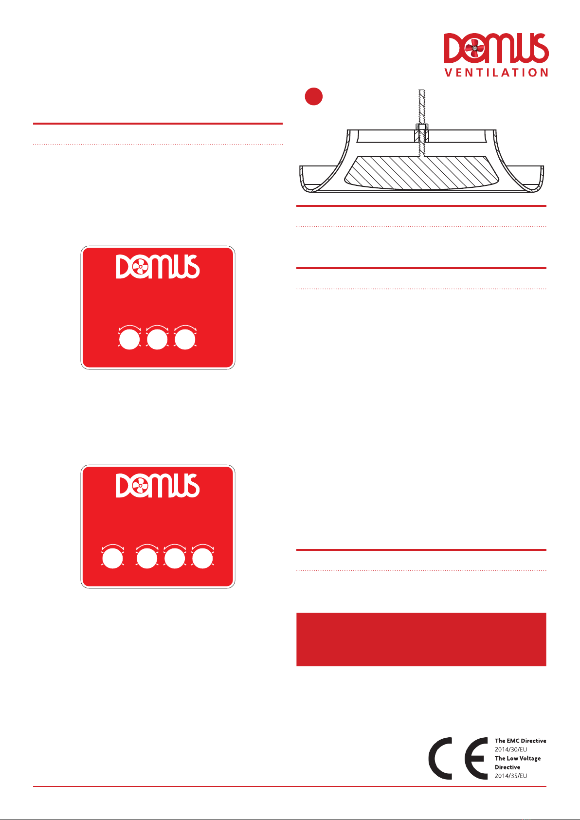
• Fully open all of the air valves (see figure 11).
• Switch the system to boost.
• Close all internal and external doors and windows.
• Measure the total air volume of the extract valves (wet rooms).
• To adjust the ‘boost’ control on the wiring centre in order to
achieve the whole dwelling extract ventilation rate, remove the rubber
tamper-deterrent cap and use Domus Ventilation commissioning
adjustment tool, SPR439.
• Adjust individual room air valves to achieve the individual room
boost extract rates.
• Switch the system to low.
• Measure the total air volume of the valves.
• To adjust the ‘trickle’ control on the wiring centre in order to
achieve the whole dwelling extract ventilation rate, remove the rubber
tamper-deterrent cap and use Domus Ventilation commissioning
adjustment tool, SPR439.
• To adjust the ‘remote humidity’ (%RH) sensor on the wiring centre,
remove the rubber tamper-deterrent cap and use Domus Ventilation
commissioning adjustment tool, SPR439.
• Using the lock nuts fitted to the air valves, lock in position (see
figure 11).
• Refit the rubber tamper deterrent caps to the lid of the wiring
centre.
10.0 Maintenance
The CMX-MULTI / CMX-MULTI-H appliance is essentially maintenance
free.
11.0 Warranty
The 2 year warranty starts from the day of delivery and includes first
year parts and labour, remaining year parts only. This warranty is void if
the equipment is modified without authorisation, is incorrectly applied,
misused, disassembled, or not installed, commissioned and maintained
in accordance with the details contained in this manual and general
good practice.
The product warranty applies to the UK mainland and in accordance
with Clause 14 of our Conditions of Sale. Customers purchasing from
outside of the UK should contact Domus Ventilation Sales office for
further details.
The above warranty does not apply to nor cover the repair of any
problem or fault with the product which arises as a result of: (a) failure
to install, operate, maintain and/or repair the product or any associated
parts and components (including any ducting) using reasonable skill
and care and in accordance with the instructions provided with it
(unless the original installation, maintenance or repair which gave rise
to the problem or fault was carried out by or on the behalf of Domus
Ventilation in which case this exclusion will not apply); (b) use of the
product for any purposes other than those for which it is designed;
(c) modifications made to the product by anyone other than Domus
Ventilation or its approved contractors; (d) deliberate damage; and/or (e)
damage caused by fire, flood or other water damage, explosions, rust or
corrosion.
12.0 TECHNICAL SUPPORT
For technical assistance or further product information, including spare
parts and replacement components, please contact Domus Ventilation
via below contact details.
Telephone 03443 715 523
11
V E N T I L A T I O N
CMX-MULTI
www.domusventilation.co.uk
-
+
-
+
purge boost trickle
-
+
-
+
-
+
-
+
%RH purge boost trickle
-
+
V E N T I L A T I O N
CMX-MULTI
www.domusventilation.co.uk
Domus Ventilation
Block C, Van Court, Caerphilly CF83 3ED, United Kingdom
Email: [email protected]
Tel: 03443 715 523
www.domusventilation.co.uk
Technical or commercial considerations may, from time to time, make it
necessary to alter the design, performance and dimensions of equipment
and the right is reserved to make such changes without prior notice.
LAB1356R | NOVEMBER 2018 PAGE 6
This manual suits for next models
1
Table of contents
Other Domus Ventilation Fan manuals

Domus Ventilation
Domus Ventilation SVC100B User manual

Domus Ventilation
Domus Ventilation HRXE User manual

Domus Ventilation
Domus Ventilation DX Series Instruction Manual

Domus Ventilation
Domus Ventilation DX Series Instruction Manual

Domus Ventilation
Domus Ventilation Sapphire DME100C Centrifugal dMEV User manual

Domus Ventilation
Domus Ventilation HRXE-HERA User manual

Domus Ventilation
Domus Ventilation Sapphire GTF100 User manual

Domus Ventilation
Domus Ventilation HRXE-AURA User manual

Domus Ventilation
Domus Ventilation CMX-S User manual

Domus Ventilation
Domus Ventilation DX Series Instruction Manual