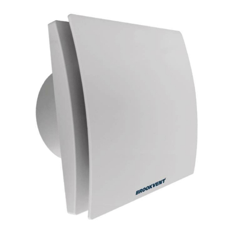
BrookVent airstream DMEV 100 HT Mounting instructions

SINGLE FLOW DECENTRALISED
MECHANICAL VENTILATION UNIT
FOR CONTINUOUS RUNNING
Installation, maintenance & user manual
PRODUCT CODE DESCRIPTION
AF 90-DMEV-100HT
brookvent.co.uk
airstream DMEV 100 HT
DMEV HT

CONTENTS
PLEASE KEEP THESE INSTRUCTIONS WITH THE PRODUCT.
Please read this manual fully prior to installing the MVHR unit.
1.0 Introduction ............................................................................................................................
1.1 Model Variations ............................................................................................................................
1.2 Product Guarantee ............................................................................................................................
2.0 Safety .........................................................................................................................................
2.1 Technical specifications ............................................................................................................................
3.0 Operation .............................................................................................................................................
3.1 Minimum continuous speed ........................................................................................................................
3.2 Intermediate speed ............................................................................................................................
3.3 Maximum speed ............................................................................................................................
3.4 Installation type .............................................................................................................................
3.5 Constant flow operation ............................................................................................................................
3.6 Humidistat ................................................................................................................................
3.7 Run-on timer .............................................................................................................................
4.0 Installation ..............................................................................................................................
5.0 Mounting and wiring diagram ....................................................................................................................
6.0 Maintenance/Cleaning ............................................................................................................................
7.0 ErP Directive - Regulations 1253/2014 - 1254/2014 ..............................................................................
8.0 Disposal and recycling ............................................................................................................................
Customer support ............................................................................................................................
3
3
3
4
5
5
6
6
6
6
7
7
7
8
8
12
13
14
14
IMPORTANT
This appliance is not intended for use by persons (including children) with reduced physical sensory or mental
capabilities, or lack of experience and knowledge, unless they have been given supervision or instruction concer-
ning use of the appliance by a person responsible for their safety.

1.0 Introduction
DMEV is a decentralised mechanical ventilation unit designed to ensure air extraction in small/medium-sized
rooms. Suitable for air discharge in the presence of long ducted system. Wall, ceiling or window installation (fig.1).
Read this manual carefully before using the product and keep it in a safe place for reference.
This product was constructed up to standard and in compliance with regulations relating to electrical equipment
and must be installed by technically qualified personnel.
The manufacturer assumes no responsibility for damage to persons or property resulting from failure to observe
the regulations contained in this booklet.
1.1 Model Variations
PRODUCT CODE DESCRIPTION
AF 90-DMEV-100HT airstream DMEV 100 HT
1.2 Product Guarantee
This product is guaranteed against defects for a period of 2 years from the date of purchase with the first year
covering parts and labour and the remaining year covering parts only.
In the instance of a defect, Brookvent may repair the product, replace the product free of charge or refund the
cost of the product at Brookvent’s own discretion. In terms of installation, operation and maintenance please
follow all instructions provided. If this product has been misused, not properly maintained or handled carelessly it
may lead to this guarantee being declared void.
Brookvent does not accept liability for damage caused by non-observance of the installation instructions.
Service activities must be carried out by Brookvent or by competent installers using original Brookvent parts.
This guarantee does not aect your statutory right as a consumer.
Brookvent operates a policy of continuous innovation and improvement and thus reserves the right to alter
product specifications and appearances without notice.
3

2.0 Safety
The device should not be used for applications other than those specified in this manual.
After removing the product from its packaging, verify its condition. In case of doubt, contact a qualified
technician. Do not leave packaging within the reach of small children or people with disabilities.
Do not touch the appliance with wet or damp hands/feet.
This appliance can be used by children aged from 8 years and above and persons with reduced physical,
sensory or mental capabilities or lack of experience and knowledge if they have been given supervision or in
struction concerning use of the appliance in a safe way and understand the hazards involved. Children shall
not play with the appliance. Cleaning and user maintenance shall not be made by children without supervision.
Do not use the product in the presence of flammable vapours, such as alcohol, insecticides, gasoline, etc.
If any abnormalities in operation are detected, disconnect the device from the mains supply and contact a
qualified technician immediately. Use original spare parts only for repairs.
The electrical system to which the device is connected must comply with regulations.
Before connecting the product to the power supply or the power outlet, ensure that:
- the data plate (voltage and frequency) correspond to those of the electrical mains
- the electrical power supply/socket is adequate for maximum device power. If not, contact a qualified
technician.
The device should not be used as an activator for water heaters, stoves, etc., nor should it discharge into hot
air/fume vent ducts deriving from any type of combustion unit. It must expel air outside via its own
special duct.
Operating temperature: 0°C up to +40°C.
The device is designed to extract clean air only, i.e. without grease, soot, chemical or corrosive agents,
or flammable or explosive mixtures.
Do not leave the device exposed to atmospheric agents (rain, sun, snow, etc.).
Do not immerse the device or its parts in water or other liquids.
Turn o the main switch whenever a malfunction is detected or when cleaning.
For installation an omnipolar switch should be incorporated in the fixed wiring, in accordance with the wiring
regulations, to provide a full disconnection under overvoltage category III conditions
(contact opening distance
equal to or greater than 3mm).
If the supply cord is damaged, it must be replaced by the manufacturer, its service agent or similarly qualified
persons in order to avoid a hazard.
Do not obstruct the fan or exhaust grille to ensure optimum air passage.
Ensure adequate air return into the room in compliance with existing regulations in order to ensure proper
device operation.
If the environment in which the product is installed also houses a fuel-operating device (water heater, methane
stove etc., that is not a “sealed chamber” type), it is essential to ensure adequate air intake, to ensure good
combustion and proper equipment operation.
Install the product so that the impeller is not accessible from the air outlet side as verified by contact with the
Test Finger (test probe “B” of the norm EN61032) in compliance with the current safety regulations.
Attention: do not mount the product on the ceiling without this kit.
4
2.1 Technical specifications
Material: high quality, impact and UV-resistant ABS colour RAL 9010.
Design front cover removable for cleaning without the use of tools.
High eciency aerodynamic fan with “winglet” blades to optimise quietness and eciency.
Single phase EC Brushless motor for energy saving, with integral thermal protection.
Motor mounted on high quality ball bearings.
Selectable minimum speed for continuous running and intermediate speed.
Option to boost from minimun speed through LS connection.
Selection of the installation type (through wall or in-room).
Selection of smart humidity control and intelligent run-on timer.
Selection of constant volume mode.
Suitable for continuous running.
The fan is double insulated: no earth connection is required.
IPX4 wall installation; IPX2 ceiling installation.
Power supply 220-240V~ 50/60Hz
3.0 Operation
Upon power-up, the unit runs at the minimum continuous speed.
If humidistat or timer is activated, the unit runs at the intermediate speed.
If the external switch is activated, the unit runs at the maximum speed.
After the external switch is o, the unit continues to run at the intermediate speed for a period of time, then it returns
to the selected minimum speed (or to the intermediate speed in case humidistat or run-on timer operation is on).
The functionalities can be set/enabled through the Dip Switches A and B on
the electronic circuit (with disconnected from the main supply unit).
5
B
1 32 4
on
0
on
0
A

6
3.1 MINIMUM CONTINUOUS SPEED
Upon power-up, the unit runs at the minimum continuous speed settable from 0 to 58m3/h (i.e. from 0 to 16l/s)
by means of the switches as per table Dip Switch A.
3.2 INTERMEDIATE SPEED
The unit runs automatically at the intermediate speed settable from 29 to 72m3/h (i.e. from 8 to 20l/s) by means of the
switches as per table Dip Switch A.
The intermediate speed can be activated when either of the below conditions have been met:
- the humidistat has been activated;
- the run-on timer has been activated.
3.3 MAXIMUM SPEED
The maximum speed fixed, at 90m3/h (i.e. 25l/s) in through-wall or 72m3/h (i.e. 20l/s) in in-room installation, can be
activated through external switch, remote ambient sensor or light switch.
3.4 INSTALLATION TYPE
Based on the selected installation type, the unit scales its speed (minimum, intermediate and maximum) to obtain the
selected air flow rates.
- Through-wall installation: unit is typically mounted on an external wall or window and discharge direct to the outside.
- In-room installation: unit is typically mounted on the ceiling or internal wall which are ducted to the outside.
NOTE: the unit runs at a higher speed when In-room installation is selected.
The installation type can be selected by means of the switches as per table Dip Switch A.
DIP SWITCH A
1 2 3 4 installation
min speed intermediate speed max speed
m3/h l/s m3/h l/s m3/h l/s
0 0 0 0 default through-wall 18 5 47 13 90 25
0 0 on 0 through-wall 18 5 29 8 90 25
0 on 0 0 through-wall 29 8 47 13 90 25
0 on on 0 through-wall 29 8 40 11 90 25
on 0 0 0 through-wall 40 11 47 13 90 25
on 0 on 0 through-wall 47 13 58 16 90 25
on on 0 0 through-wall 58 16 72 20 90 25
on on on 0 through-wall 0 0 47 13 90 25
0 0 0 on in-room 18 5 47 13 72 20
0 0 on on in-room 18 5 29 8 72 20
0 on 0 on in-room 29 8 47 13 72 20
0 on on on in-room 29 8 40 11 72 20
on 0 0 on in-room 40 11 47 13 72 20
on 0 on on in-room 47 13 58 16 72 20
on on 0 on in-room 58 16 72 20 72 20
on on on on in-room 0 0 47 13 72 20

7
DIP SWITCH B
1costant ow
on enabled
0 disabled default
3.5 CONSTANT FLOW OPERATION
When the constant flow operation in enabled, the unit speeds up or slows down depending on
the variations of the resistances caused by long length ducting or external windy conditions.
The constant flow operation can be enabled/ disabled by means of switch 1 of Dip Switch B.
DIP SWITCH B
2 humidistat
on disabled
0 AUTO default
3.6 HUMIDISTAT
The unit is equipped with a humidity sensor that operates in AUTO mode, i.e. the humidistat,
which records the humidity levels, triggers if there is a steep variation of the humidity and if
humidity level is over 65%. If the humidistat is activated, the unit runs at the intermediate
speed and continues to run for a fixed time of 5 minutes after the umidity level stabilizes.
The humidistat can be enabled/ disabled by means of switch 2 of Dip Switch B.
3.7 RUN-ON TIMER
The unit is equipped with a run-on timer. When the external switch is turned o, the unit
continues to run at the intermediate speed for the a period of time defined as follows:
- if the external switch is activated for less than 3 minutes, the unit does not run-on;
- if the external switch is activated for between 3 and 10 minutes, the unit runs on for
5 minutes;
- if the external switch is activated for between 10 and 20 minutes, the unit runs on for
10 minutes;
- if the external switch is activated for over 20 minutes, the unit runs on for 15 minutes.
When the time is expired, the unit returns to the minimum continuous speed.
The run-on Timer can be enabled/disabled by means of switch 3 of Dip Switch B.
DIP SWITCH B
3 timer
on disabled
0 AUTO default

8
4.0 INSTALLATION (Pic.1)
5.0 MOUNTING AND WIRING DIAGRAM
wall
4
6
2
5
ducted
direct exhausting
DETAIL A
A
click!
DETAIL B
FIG.2: CONTENUTO IMBALLO QDMEV
2 NUOVE FIGURE: ASSEMBLAGGIO STATORE
(DA INSERIRE TRA LE FIG. 5 E 6)
B
23
ceiling (accessory on demand)

9
DMEV 100 = ø99mm
Ø
7
IMMAGINE 1:
VERIFICARE LA POSSIBILITA' DI LASCIARE L'INSTALLAZIONE A FINESTRA
AGGIUNGENDO L'OPERAZIONE DI TOGLIERE LO STATORE
OPPURE TOGLIERE L'IMMAGINE DELL'INSTALLAZIONE A FINESTRA
(CHIEDERE A SABRINA)
IMMAGINE 2 - 3- 4 - 5 OK
IMMAGINE 6 ELIMINARE LA NOTA CON RIFERIMENTO AL QUANTUM AX 150
SOSTITUIRE LA SCRITTA QUANTUM AX 100 CON LA SCRITTA QDMEV100
IMMAGINE 7
IMMAGINE 8A - 9A OK!
IMMAGINE 10A
IMMAGINE 11A OK!
IMMAGINE 12A
CAVO A PARETE
CAVO SOTTO TRACCIA
IMMAGINE 8B - 9B - 10B OK!
IMMAGINE 11B IMMAGINE 12B
8
SURFACE CABLE
H03VV-F ; H05VV-F
2 X 0,5 ÷ 1,5mm2
3 X 0,5 ÷ 1,5mm2
4xø5mm
9A
DETAIL A
A
click!
DETAIL B
FIG.2: CONTENUTO IMBALLO QDMEV
2 NUOVE FIGURE: ASSEMBLAGGIO STATORE
(DA INSERIRE TRA LE FIG. 5 E 6)
B
6
DETAIL A
A
click!
DETAIL B
FIG.2: CONTENUTO IMBALLO QDMEV
2 NUOVE FIGURE: ASSEMBLAGGIO STATORE
(DA INSERIRE TRA LE FIG. 5 E 6)
B
10A
IMMAGINE 1:
VERIFICARE LA POSSIBILITA' DI LASCIARE L'INSTALLAZIONE A FINESTRA
AGGIUNGENDO L'OPERAZIONE DI TOGLIERE LO STATORE
OPPURE TOGLIERE L'IMMAGINE DELL'INSTALLAZIONE A FINESTRA
(CHIEDERE A SABRINA)
IMMAGINE 2 - 3- 4 - 5 OK
IMMAGINE 6 ELIMINARE LA NOTA CON RIFERIMENTO AL QUANTUM AX 150
SOSTITUIRE LA SCRITTA QUANTUM AX 100 CON LA SCRITTA QDMEV100
IMMAGINE 7
IMMAGINE 8A - 9A OK!
IMMAGINE 10A
IMMAGINE 11A OK!
IMMAGINE 12A
CAVO A PARETE
CAVO SOTTO TRACCIA
IMMAGINE 8B - 9B - 10B OK!
IMMAGINE 11B IMMAGINE 12B
11A

10
IMMAGINE 1:
VERIFICARE LA POSSIBILITA' DI LASCIARE L'INSTALLAZIONE A FINESTRA
AGGIUNGENDO L'OPERAZIONE DI TOGLIERE LO STATORE
OPPURE TOGLIERE L'IMMAGINE DELL'INSTALLAZIONE A FINESTRA
(CHIEDERE A SABRINA)
IMMAGINE 2 - 3- 4 - 5 OK
IMMAGINE 6 ELIMINARE LA NOTA CON RIFERIMENTO AL QUANTUM AX 150
SOSTITUIRE LA SCRITTA QUANTUM AX 100 CON LA SCRITTA QDMEV100
IMMAGINE 7
IMMAGINE 8A - 9A OK!
IMMAGINE 10A
IMMAGINE 11A OK!
IMMAGINE 12A
CAVO A PARETE
CAVO SOTTO TRACCIA
IMMAGINE 8B - 9B - 10B OK!
IMMAGINE 11B IMMAGINE 12B
13A
ø10mm
ødd
12A
2 X 0,5 ÷ 1,5mm2
3 X 0,5 ÷ 1,5mm2
RECESSED CABLE ENTRY
H03VV-F ; H05VV-F
4 x ø 5 mm
9B
10B 11B

11
ON
OFF
IMMAGINE 1:
VERIFICARE LA POSSIBILITA' DI LASCIARE L'INSTALLAZIONE A FINESTRA
AGGIUNGENDO L'OPERAZIONE DI TOGLIERE LO STATORE
OPPURE TOGLIERE L'IMMAGINE DELL'INSTALLAZIONE A FINESTRA
(CHIEDERE A SABRINA)
IMMAGINE 2 - 3- 4 - 5 OK
IMMAGINE 6 ELIMINARE LA NOTA CON RIFERIMENTO AL QUANTUM AX 150
SOSTITUIRE LA SCRITTA QUANTUM AX 100 CON LA SCRITTA QDMEV100
IMMAGINE 7
IMMAGINE 8A - 9A OK!
IMMAGINE 10A
IMMAGINE 11A OK!
IMMAGINE 12A
CAVO A PARETE
CAVO SOTTO TRACCIA
IMMAGINE 8B - 9B - 10B OK!
IMMAGINE 11B IMMAGINE 12B
12B
IMMAGINE 1:
VERIFICARE LA POSSIBILITA' DI LASCIARE L'INSTALLAZIONE A FINESTRA
AGGIUNGENDO L'OPERAZIONE DI TOGLIERE LO STATORE
OPPURE TOGLIERE L'IMMAGINE DELL'INSTALLAZIONE A FINESTRA
(CHIEDERE A SABRINA)
IMMAGINE 2 - 3- 4 - 5 OK
IMMAGINE 6 ELIMINARE LA NOTA CON RIFERIMENTO AL QUANTUM AX 150
SOSTITUIRE LA SCRITTA QUANTUM AX 100 CON LA SCRITTA QDMEV100
IMMAGINE 7
IMMAGINE 8A - 9A OK!
IMMAGINE 10A
IMMAGINE 11A OK!
IMMAGINE 12A
CAVO A PARETE
CAVO SOTTO TRACCIA
IMMAGINE 8B - 9B - 10B OK!
IMMAGINE 11B IMMAGINE 12B
13B
16
CLICK
17
14
LS
L
N
L
N
15
• When wiring to the PCB terminals, do not overtighten
the screws: maximum torque 0,15Nm.
18 19 20

12
6.0 MAINTENANCE / CLEANING
22
23
25
24
21
ON
OFF

13
7.0 ErP Directive - Regulations 1253/2014 - 1254/2014
a) Mark -BROOKVENT
b) Model -
DMEV 100 HT
c) SEC class -
C
c1) SEC warm climates kWh/m2.a -11,1
c2) SEC average climates kWh/m2.a -25,5
c3) SEC cold climates kWh/m2.a -50,6
Energy label -No
d) Unit typology -Residential - unidirectional
e) Type of drive - Multi-speed drive
f) Type of Heat Recovery System - Absent
g) Thermal eciency of heat recovery %N/A
h) Maximum flow rate m3/h 97
i) Electric power input at maximum flow rate W 6
j) Sound power level (LWA) dBA 50
k) Reference flow rate m3/h 68
I) Reference pressure dierence Pa 20
m) Specific power input (SPI) W/m3/h 0,040
n1) Control factor -0,65
n2) Control typology -Local demand control
o1) Maximum internal leakage rate %N/A
o2) Maximum external leakage rate %N/A
p1) Internal mixing rate %N/A
p2) External mixing rate %N/A
q) Visual filter warning -N/A
r) Instructions to install regulated grilles - Check the instruction booklet
s) Internet address for pre/disassembly
instructions - www.brookvent.co.uk
t) Airflow sensitivity to pressure variations %N/A
u) Indoor/outdoor air tightness m3/h 52
v1) AEC - Annual electricity consumption - warm
climates kWh 0,3
v2) Consumo annuo di energia (AEC) climi
temperati; AEC - Annual electricity kWh 0,3
v3) AEC - Annual electricity consumption - cold
climates kWh 0,3
w1) AHS - Annual heating saved - warm climates kWh 11,9
w2) AHS - Annual heating saved - average climates kWh 26,2
w3) AHS - Annual heating saved - cold climates kWh 51,3

14
Customer Support
At Brookvent we pride ourselves on providing Gold Standard after sales and support to all customers.
Please feel free to contact one of our specialist team about any query you may have and we will be more than
happy to assist you.
BROOKVENT
Brook House,
Dunmurry Industrial Estate,
Dunmurry,
Belfast
Northern Ireland, BT17 9HU
T: +44 (0) 28 9061 6505
Email: hello@brookvent.co.uk
It is important to retain this manual and make a copy available to any person using or working with (maintaining)
the system.
Brookvent operates a policy of continuous innovation and improvement and thus reserves the right to alter
product specifications and appearances without notice.
8.0 Disposal and recycling
Information on disposal of units at the end of life. This product complies with EU Directive 2002/96/EC.
The symbol of the crossed-out dustbin indicates that this product must be collected separately from other waste at the
end of its life. The user must, therefore, dispose of the product in question at suitable electronic and electro-technical
waste disposal collection centres, or else send the product back to the retailer when purchasing a new, equivalent type
device. Separate collection of decommissioned equipment for recycling, treatment and environmentally compatible
disposal helps to prevent negative eects on the environment and on health and promotes the recycling of the mate-
rials that make up the equipment.
Improper disposal of the product by the user may result in administrative sanctions as provided by law.

V1 24.05.2023 UK
brookvent.co.uk
DMEV HT
This manual suits for next models
1
Table of contents
Other BrookVent Fan manuals

BrookVent
BrookVent AF 90-DMEV-100 User manual

BrookVent
BrookVent Aircycle 1.1 Instruction Manual

BrookVent
BrookVent AIRSTREAM XE+ Mounting instructions

BrookVent
BrookVent aircycle 4.1 User manual

BrookVent
BrookVent AS 92-ACE-H-125 User guide

BrookVent
BrookVent BTP EC 100 Mounting instructions

BrookVent
BrookVent 90-0103-WDS-01 Mounting instructions

BrookVent
BrookVent AIRVENT SM ACOUSTIC Operating instructions

BrookVent
BrookVent AirVent SM 1200+ User manual