Donaldson Torit E-100 User manual

Installation
and Operation Manual
IOM 1B0510107
Revision 1
Centrifugal Mist Collector
E-100, E-200, E-300, E-500
EA-700, EA-900, and EA-905
Installation,
Operation, and
Service Information
This manual is property of the owner. Leave with the unit when set-up and start-
up are complete. Donaldson Company reserves the right to change design and
specifications without prior notice.
This is the safety alert
symbol. It is used to
alert you to potential personal
injury hazards. Obey all safety
messages that follow this symbol to
avoid possible injury or death.
Illustrations are for reference only
as actual product may vary.

Donaldson Company, Inc.
2
Combustible materials such as buffing lint, paper, wood, metal dusts, weld fume, or flammable coolants
or solvents represent potential fire and/or explosion hazards. Use special care when selecting, installing,
and operating all dust, fume, or mist collection equipment when such combustible materials may be
present in order to protect workers and property from serious injury or damage due to a fire and/or
explosion.
Consult and comply with all National and Local Codes related to fire and/or explosion properties of
combustible materials when determining the location and operation of all dust, fume, or mist collection
equipment.
When combustible materials are present you must consult with an expert in fire extinguishing and/or
explosion protection systems, who is also familiar with the local codes, for support and guidance on the
selection and installation of an appropriate fire and/or explosion protection system.
DO NOT allow sparks, cigarettes or other burning objects to enter the hood or duct of any dust, fume,
or mist collection equipment as these may initiate a fire or explosion of any combustible materials
accumulated in the collector.
Improper operation of a dust, fume, or mist control system may contribute to conditions in the work area
or facility that could result in severe personal injury and product or property damage. Check that all
dust, fume, or mist collection equipment is properly selected, installed, and operated for its intended use.
This manual contains specific precautionary statements relative to worker safety. Read this manual
thoroughly and comply as directed. Instruct all personnel on the safe use and maintenance procedures related
to this equipment. Discuss any questions on the application, use, or maintenance of this equipment with a
Donaldson Torit representative.
For optimum collector performance, use only Donaldson Torit replacement parts.
Application of Mist Control Equipment

Centrifugal Mist Collector
3
Data Sheet
Model Number _______________________________ Serial Number__________________________________
Ship Date ____________________________________ Installation Date________________________________
Customer Name______________________________________________________________________________
Address _____________________________________________________________________________
_____________________________________________________________________________
Filter Type _____________________________________________________________________________
Accessories _____________________________________________________________________________
Other _____________________________________________________________________________
Contents
Safety Statements ...................................................2
Data Sheet..............................................................3
Description.............................................................4
Purpose and Intended Use .....................................4
Operation...............................................................5
Inspection on Arrival..............................................6
Installation Codes and Procedures..........................6
Installation.............................................................6
Site Selection, Grade-Mounted Units................6
Unit Location ...................................................6
Rigging Instructions ...............................................7
Hoisting Information .......................................7
Electrical Wiring ....................................................7
Standard Equipment...............................................8
Ductwork.........................................................8
Drain Connection.............................................9
Electrical Connection .....................................10
Optional Equipment.............................................11
Prefilter Trap..................................................11
In-Cover Trap ................................................11
In-Cover Impinger..........................................12
HEPA Filter....................................................13
Preliminary Start-Up Check..................................14
Service Information..............................................14
Operational Checklist ....................................14
Disposable Filter Liner Replacement ..............14
Primary Filter Replacement ............................14
Secondary Filter Replacement ........................14
Troubleshooting ...................................................15
Service Notes........................................................16
Warranty..............................................................20
DANGER indicates a hazardous situation which, if not avoided, will result in
death or serious injury.
WARNING indicates a hazardous situation which, if not avoided, could result in
death or serious injury.
CAUTION, used with the safety alert symbol, indicates a hazardous situation
which, if not avoided, could result in minor or moderate injury.
NOTICE is used to address practices not related to personal injury.

Donaldson Company, Inc.
4
Description
Centrifugal mist collectors are compact, high
efficiency, centrifugal mist collection systems
designed to collect, filter, and reclaim liquid mist
generated in machine tool or process operations.
The compact size allows direct machine mounting
which integrates the collection system directly to
the mist-generating machine or process. Four stages
of filtration provide effective indoor air pollution
control.
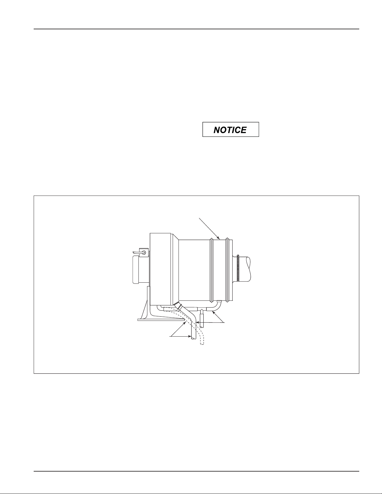
Optional prefilters, impingers, and afterfilters
provide additional filtration. Prefilters are used to
remove chips or solid particles before they enter
the rotating drum and impingers remove heavy
sprays of raw fluids. Optional HEPA afterfilters,
available in standard and high-capacity sizes, remove
smoke generated in a machine process while carbon
afterfilters remove gas vapor and odors.
Purpose and Intended Use
Misuse or modification of
this equipment may result in
personal injury.
Do not misuse or modify.
Centrifugal mist collectors are intended for
separation of various liquid particulates. It is not a
dust collector and should not be used to filter solid
particulate. The mist collector is designed to filter
mild amounts of smoke and only smoke of an oily
nature or mixed with oil mist. Typical applications
include chip-generating operations such as screw and
bar machines, CNC turning and milling machines,
and applications using straight oil coolants. Some
applications such as grinding, especially those with
heavy metal-removal rates, can cause a buildup of
grinding swarf or other solid particulate. Using a
prefilter trap is strongly recommended to extend
the maintenance cycle of the mist collector in these
operations.
The collector must be sized to the application or
filtration will not be effective. Too little airflow will
not draw the contaminant into the filter and too
much airflow may result in the unit picking up large
or heavy solid particles increasing the frequency of
maintenance or filter replacement.
Combustible materials such as buffing lint, paper, wood, metal dusts, weld fume, or
flammable coolants or solvents represent potential fire and/or explosion hazards. Use
special care when selecting, installing, and operating all dust, fume, or mist collection equipment
when such combustible materials may be present in order to protect workers and property from
serious injury or damage due to a fire and/or explosion.
Consult and comply with all National and Local Codes related to fire and/or explosion properties
of combustible materials when determining the location and operation of all dust, fume, or mist
collection equipment.
Standard Donaldson Torit equipment is not equipped with fire extinguishing or explosion protection
systems.

Centrifugal Mist Collector
5
Unit Operation
Operation
During normal operation, mist-laden air enters the
collector through a flexible hose. The air passes
through a disposable first-stage filter and into
a second-stage primary filter. Sub-micron mist
particles are trapped and retained until they coalesce
and grow to droplet size. These filters are housed in
a spinning, perforated drum with internal radial fan
blades to promote air movement.
The droplets are spun and thrown from the
perforated drum to the inner wall of the collector
housing by centrifugal force. High velocity air drives
the liquid or oil along the housing walls, through a
circumferential slot, and into a collection chamber
where the liquid is drained. A third-stage, secondary
filter catches liquid that bypasses the slot and drains
through the secondary drain. Clean air is exhausted
through the fourth-stage, exhaust grill filter and
returned to the plant environment while the recycled
oil drains from the unit for reuse or disposal.
mist-laden air
disposable first-stage filter
second-stage primary filter
drum assembly
third-stage secondary filter
exhaust grill
exhaust grill filter
clean-air outlet

Donaldson Company, Inc.
6
Inspection on Arrival
1. Inspect unit on delivery.
2. Report any damage to the delivery carrier.
3. Request a written inspection report from the
Claims Inspector to substantiate claim.
4. File claims with the delivery carrier.
5. Compare unit received with description of
product ordered.
6. Report incomplete shipments to the delivery
carrier and your Donaldson representative.
7. Remove crates and shipping straps. Remove
loose components and accessory packages before
lifting unit from truck.
Installation Codes and Procedures
OSHA may have requirements
regarding recirculating
filtered air in your facility. Consult with
the appropriate local authorities to ensure
compliance with all codes regarding
recirculating filtered air.
Safe and efficient operation of the unit depends on
proper installation.
Authorities with jurisdiction should be consulted
before installing to verify local codes and installation
procedures. In the absence of such codes, install unit
according to the National Electric Code, NFPA No.
70-latest edition.
A qualified installation and service agent must
complete installation and service of this equipment.
All shipping materials, including shipping covers,
must be removed from the unit prior to, or during
unit installation.
Failure to remove shipping
materials from the unit will
compromise unit performance.
Installation
Site Selection, Grade-Mounted Units
The unit can be located on a reinforced concrete
foundation.
Provide clearance from heat sources and interference
with utilities when selecting the location.
Unit Location
When hazardous conditions or materials are present,
consult with local authorities for the proper location
of the collector.
Foundation or roof support must be sized to
accommodate the entire weight of the unit, plus
the weight of the collected material, piping, and
ductwork.
Prepare the foundation in the selected location.
Install anchor bolts to extend a minimum of
1 3/4-inches above foundation unless otherwise
indicated on the Specification Control drawing.
Locate the collector to ensure the shortest and
straightest inlet- and outlet-duct length, easy access
to electrical connections, and routine maintenance.

Centrifugal Mist Collector
7
Rigging Instructions
Failure to lift the collector
correctly can result in severe
personal injury or property damage.
Use appropriate lifting equipment and
adopt all safety precautions needed for
moving and handling the equipment.
A crane or forklift is recommended for
unloading, assembly, and installation of the
collector.
Location must be clear of all obstructions,
such as utility lines or roof overhang.
Suggested Tools & Equipment
Crane or Forklift Pipe Wrenches
Slings, Spreader Bars, Socket Wrenches
and Clevis Pins End Wrenches
Drift Pins Large Crescent Wrench
Clamps Drill and Drill Bits
Screwdrivers Pipe Sealant
Hoisting Information
Use all lifting points provided.
Use clevis connectors, not hooks, on lifting slings.
Use spreader bars to prevent damage to units casing.
Check the Specification Control drawing for weight
and dimensions of the unit, subassemblies, and
components to ensure adequate crane capacity.
Allow only qualified crane operators to lift the
equipment.
Refer to applicable OSHA regulations and local
codes when using cranes, forklifts, and other lifting
equipment.
Lift unit and accessories separately, and assemble
after unit is in place.
Electrical Wiring
Electrical installation must
be performed by a qualified
electrician and comply with all applicable
national and local codes.
Lock out electrical power sources before
performing service or maintenance work.
Do not install in classified hazardous
atmospheres without an enclosure rated for
the application.
All electrical wiring and connections, including
electrical grounding, should be made in accordance
with the National Electric Code, NFPA No. 70-latest
edition.
Check local ordinances for additional requirements
that apply.
The appropriate wiring schematic and electrical
rating must be used. See units rating plate for
required voltage.
If the unit is not furnished with a factory-mounted
disconnect, an electric disconnect switch having
adequate amp capacity shall be installed in
accordance with Part IX, Article 430 of the National
Electrical Code, NFPA No. 70-latest edition. Check
units rating plate for voltage and amperage ratings.
Refer to the wiring diagram for the number of wires
required for main power wiring and remote wiring.

Donaldson Company, Inc.
8
Standard Equipment
The Centrifugal mist collector is normally installed
horizontally; however, it can be installed vertically
with the inlet end down.
1. Remove the inlet covers retaining ring and
remove the cover. Discard the cardboard spacers
between the casing and the rotating drum, if
installed. The drum should now rotate freely.
Replace the inlet cover and secure with retaining
ring.
2. Remove the carriage bolts or lag screws securing
the collector base to the pallet. Retain the four
washers tied to the pedestal.
3. Secure the base to the mounting surface with
four 1/2-in machine screws. Use the four washers
retained in Step 1 as shims under the mounting
bolts if necessary.
Ductwork
1. Attach one end of the flexible hose to the inlet
cover and secure with a hose clamp.
2. Connect the opposite end to the machine
hood or enclosure with a hose clamp. Flange
connectors are available to connect the hose to
most hoods or enclosures.
Keep flexible hose length
and number of bends to a
minimum. Maintain a slope to prevent
deposits of oil from settling at low points
and blocking the air passage.
3. If rigid duct is used, connect an 18-in length of
flexible hose to the units inlet cover for easy
cover removal.

Centrifugal Mist Collector
9
Drain Connection
Primary Drain
1. Use either rigid pipe or flexible hose for the drain
connection. Use 3/4-in diameter hose for Models
E-100 and E-200, and 1-in for all other models.
2. Models E-100 and E-200 are equipped with a
1-in NPT male drain fitting and Models E-300
through EA-900 are equipped with a 1 1/4-
in NPT fitting that connects to the reservoir
eliminating the need to empty containers. A
separate container can be attached to the drain if
desired.
Secondary Drain
The secondary drain fitting is a 1/4-in NPT 900 EL
fitting and connects the same way the primary drain
connects.
Do not submerge ends of hose.
Do not connect the secondary
drain hose to the primary drain hose.
Drain Connection
in-cover trap
drain hose
without
in-cover trap
drain hose
with in-cover
trap
connect with flexible hose or rigid pipe

Donaldson Company, Inc.
10
Wiring Diagram
Electrical Connection
Electrical installation must
be performed by a qualified
electrician and comply with all applicable
national and local codes.
Lock out electrical power sources before
performing service or maintenance work.
Do not install in classified hazardous
atmospheres without an enclosure rated for
the application.
Wire unit according to the wiring diagram located
on the motor conduit box cover. Collectors be wired
for 220 or 440-Volt, 60 Hz, 3 Ph supply power.
1 2
7 8
3
9
4 5 6 1 2 3 4
7
5
8
6
9
to low voltage power supply to high voltage power supply
circled numbers correspond to wire tags located inside the junction box

Centrifugal Mist Collector
11
Optional Equipment
Prefilter Trap
Prefilter Trap
In-Cover Trap
In-Cover Trap

Donaldson Company, Inc.
12
In-Cover Impinger
In-Cover Impinger

Centrifugal Mist Collector
13
HEPA Filter
HEPA Filter

Donaldson Company, Inc.
14
Preliminary Start-Up Check
1. Check all electrical connections for tightness and
contact.
2. Check for and remove all loose items in or near
the inlet and outlet of the unit.
3. Check that all remote controls are wired into the
control system, and all service switches are in the
OFF position.
4. Check that all optional accessories are installed
properly and secured.
5. Turn power ON at source.
6. Turn the fan motor ON then OFF to check
for proper rotation by referencing the rotation
arrow located on the motors mounting plate.
Do not look into fan outlet to
determine rotation. View the
fan rotation through the back of the motor.
Check that the exhaust plenum is free of
tools or debris before checking blower/fan
rotation.
Stand clear of exhaust to avoid personal
injury.
To reverse rotation, three-phase power supply:
Turn electrical power OFF at source and switch
any two leads on the output-side of the fan-
motor starter.
Service Information
Operational Checklist
1. Monitor overall performance of the collector.
2. Monitor exhaust.
Disposable Filter Liner Replacement
Turn unit OFF and check
that drum has stopped before
removing the cover.
1. Using a felt tip marker or scribe, mark the
location of the liner ends on the face of the
drum.
2. Remove and discard disposable liner.
3. Starting at the mark made in Step 1, slide the
replacement liner under each blade until the ends
come together.
Do not trim the filter if it
seems too long. Work the
excess filter liner around the drum evenly.
4. Replace the cover and clamping ring, turn power
ON and allow unit to reach full speed.
5. Turn unit OFF and allow drum to stop. Remove
the inlet cover and inspect liner. It should be
smoothly seated and the butt joint flat. If liner
overlaps at the seam or wrinkles are present,
smooth troublesome areas by hand and repeat
Steps 4 and 5.
If unit runs rough after filter
liner replacement, shift the
liner seam a few inches to the right or left
of the reference mark.
Primary Filter Replacement
Under normal operating conditions and scheduled
filter liner replacement, the primary filter will not
require replacement. It is strongly recommended that
this filter is not removed. The dynamic balance of
the drum assembly will be affected.
Delayed maintenance or accidental damage can
make replacement necessary. Follow the same
procedure used for replacing the disposable filter.
Trial and error shifting of the seam will be necessary
to minimize vibration. If the drum is distorted, it
may be necessary to re-balance the unit.
Secondary Filter Replacement
The secondary-filter replacement requires the
removal of the rotating drum. Replace the filter by
reversing the removal process.

Centrifugal Mist Collector
15
Troubleshooting
Problem Probable Cause Remedy
Unit will not start Improper motor wire size Rewire using the correct wire gauge as specified
by national and local codes.
Not wired correctly Check and correct motor wiring for supply
voltage. See motor manufacturer's wiring
diagram. Follow wiring diagram and the
National Electric Code.
Unit not wired for available
voltage
Correct wiring for proper supply voltage.
Input circuit down Check power supply to motor circuit on all
leads.
Electrical supply circuit down Check power supply circuit for proper voltage.
Check for fuse or circuit breaker fault. Replace
as necessary.
Fuse blown Check and replace as necessary.
Junction box not wired
correctly
Check wiring in junction box for tightness and
contact.
Defective motor Replace motor.
Unit runs slow Incorrect voltage Check power supply circuit for proper voltage.
Junction box not wired
correctly
Check that the junction box is wired according
to the wiring diagram.
Single phase disconnected Check that the junction box is wired according
to the wiring diagram.
Obstruction between drum
and housing
Remove inlet cover. Remove obstruction.
Clean-air outlet
discharging dust
Disposable filter liner dirty See Disposable Filter Liner Replacement section.
Undersized unit Unit must be sized for the application. Contact
Donaldson for assistance.
Excess Vibration Mounting bolts loose Tighten bolts.
Foreign object in drum Check and remove obstruction.
Disposable filter liner dirty See Disposable Filter Liner Replacement section.
Drum assembly distorted Rebalance drum assembly. Contact Donaldson
for assistance.

Donaldson Company, Inc.
16
Service Notes
Date Service Performed Notes

Centrifugal Mist Collector
17
Date Service Performed Notes

This Page Intentionally Left Blank


© 2002 Donaldson Company, Inc. Printed in USA
IOM 1B0510107, Revision 1 May 2008
Parts and Service
The Donaldson Torit Warranty
Donaldson warrants to the original purchaser that the major structural components of the goods will be
free from defects in materials and workmanship for ten (10) years from the date of shipment, if properly
installed, maintained and operated under normal conditions. Donaldson warrants all other Donaldson
built components and accessories including Donaldson Airlocks, TBI Fans, TRB Fans, Fume Collector
products, Donaldson built electrical control components and Donaldson built Afterfilter housings for
twelve (12) months from date of shipment. Donaldson warrants Donaldson built filter elements to be free
from defects in materials and workmanship for eighteen (18) months from date of shipment. Donaldson
does not warrant against damages due to corrosion, abrasion, normal wear and tear, product modification,
or product misapplication. Donaldson also makes no warranty whatsoever as to any goods manufactured
or supplied by others including electric motors, fans and control components. After Donaldson has been
given adequate opportunity to remedy any defects in material or workmanship, Donaldson retains the
sole option to accept return of the goods, with freight paid by the purchaser, and to refund the purchase
price for the goods after confirming the goods are returned undamaged and in usable condition. Such a
refund will be in the full extent of Donaldsons liability. Donaldson shall not be liable for any other costs,
expenses or damages whether direct, indirect, special, incidental, consequential or otherwise. The terms
of this warranty may be modified only by a special warranty document signed by a Director, General
Manager or Vice President of Donaldson. Failure to use genuine Donaldson replacement parts may void
this warranty. THERE EXIST NO OTHER REPRESENTATIONS, WARRANTIES OR GUARANTEES
EXCEPT AS STATED IN THIS PARAGRAPH AND ALL OTHER WARRANTIES INCLUDING
MERCHANTABILITY AND FITNESS FOR A PARTICULAR PURPOSE, WHETHER EXPRESS OR
IMPLIED ARE HEREBY EXPRESSLY EXCLUDED AND DISCLAIMED.
Other manuals for E-100
1
This manual suits for next models
6
Table of contents
Popular Solar Panel manuals by other brands

Solar Frontier
Solar Frontier SolarSet 2.0 Installation and operating manual

Sferasol Energy
Sferasol Energy SFERASOL SF-S Use and maintenance

fanttik
fanttik EVO SOLAR 100 user manual

ECO-WORTHY
ECO-WORTHY ECO-120W user manual

REC
REC ALPHA Series installation instructions

Phaesun
Phaesun Mare Flex Series manual

STATCON ENERGIAA
STATCON ENERGIAA SEOG Series product manual

SunEdison
SunEdison Silvantis 60 installation manual

Roofit.Solar
Roofit.Solar ClicSeam Safety and installation manual

Clenergy
Clenergy V-ezRack SolarRoof installation guide

STIEBEL ELTRON
STIEBEL ELTRON TEGREON 255 P Operation and installation

Coleman
Coleman 38001 Assembly & installation