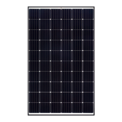
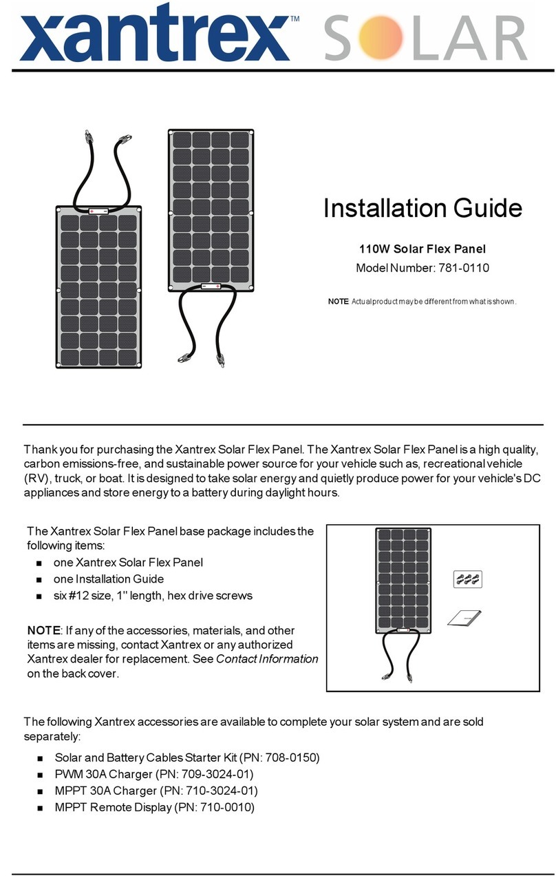
triple solar 101125 User manual

manual
heat pump panels
triple solar
heating without gas

versie 22-01-2021
S
t
a
n
Inhoudsopgave
1. General information........................................................................................ 2
Safety, legal requirements, standards and regulations....................................... 2
Allowed load of the panels ............................................................................. 2
Transport regulations .................................................................................... 2
2. Components ................................................................................................... 3
Panels ......................................................................................................... 3
Mounting rails per panel ................................................................................ 3
PVT basis package 1-s, first panel in a row SPIGOT........................................... 3
PVT basis package 2, next panel in a row......................................................... 4
Pitched roof, bracket set ................................................................................ 4
Pitched roof, feet for EPDM/bitumen roof ......................................................... 5
Pitched roof assembly package with cover plate................................................ 5
Pitched roof gland with flexible hoses .............................................................. 5
Flat roof mounting with Sunbeam frame .......................................................... 5
Heat pump assessories package.................................................................... 6
Other articles ............................................................................................. 6
3. Positioning the panel area .............................................................................. 7
Distance between rows on flat roof. ................................................................ 7
Distances between rows on pitched roof .......................................................... 7
4. Preparation for pitched roof, tiled roof ........................................................... 8
5. Preparing a flat roof ..................................................................................... 11
6. Preparing a EPDM/bitumen roof ................................................................... 12
7. Placing the panels on the mounting rails ...................................................... 13
The TS clamping profile ................................................................................13
Mounting of the panels .................................................................................14
Mounting the TS clamping profile ...................................................................16
Mounting connecting hoses ...........................................................................17
Connecting the PV panels electrically..............................................................17
8. Connecting the pipes .................................................................................... 18
Material and position ....................................................................................18
Pipe diameters of source pipes ......................................................................21
Hydraulic plan .............................................................................................21
Filling medium.............................................................................................23
Installing the expansion vessel ......................................................................23
Connecting thermostatic mixing valve ............................................................23
Insulation ...................................................................................................23
Micro air bubble separator ............................................................................24
9. Finishing....................................................................................................... 25
Pitched roof –pipe clamps and cover plate......................................................25
Mounting rail covers.....................................................................................27
10. Activating the system ................................................................................. 27
Testing leak tightness, filling and system pressure .........................................27
Commissioning the heat pump (IBS) ............................................................28
11. Warranty conditions and maintenance ....................................................... 29

2
Triple Solar assembly instruction PVT heat pump panels UK January 2021
1. General information
Watch the video on our website with assembly instructions - www.triplesolar.eu
Safety, legal requirements, standards and regulations
Working safely is key. At a minimum, your basic equipment should include:
- Safety shoes, helmet, cut-resistant work gloves
- Fall protection in accordance with the legal standards
The installation must be assembled in accordance with the legal regulations and standards
(including NEN1010). Also take into account fire safety regulations such as:
- Compatible MC4 connectors
- Electricity in cable ducts
The roof brackets are not intended to be used for standing on.
Stop the assembly in case of strong wind gusts
Allowed load of the panels
The heat pump panels are designed for the following allowable loads:
Pressure load (Snow, Wind): 5400 Pa
Tensile load (Wind): 2400 Pa
The mounting material supplied by Triple Solar is TÜV approved and in accordance with
Eurocode EN 1991-1-4. Manufacturer's instructions must be observed in order to claim
warranty.
Mount heat pump panels at an angle between 10° and 30°. (Areas with a lot of snow: install
heat pump panels at an angle between 30° and 90°).
If the angle of inclination is greater or if there is a large wind load, more roof brackets may be
required than indicated in these instructions.
Transport regulations
The heat pump panels may only be carried via the profiles on the short side. The tubes and
slats must not be used for this purpose. Aids such as lifting straps, etc. must not be attached
to the tubes.
As long as the heat pump panels are stored, the sealing caps remain on the tube openings to
prevent dirt from entering the tubes.

3
Triple Solar assembly instruction PVT heat pump panels UK January 2021
2. Components
Panels
Art. nr.
Description
Measures
101125
PVT 380Wp panel, Model XL 200
1985mm x 995mm
101210
PVT 320Wp panel
1668mm x 995mm
Mounting rails per panel
Art. nr.
Description
Specification
Number
Illustration
322101
Mounting rail
2120 mm -
Aluminum
2x per panel
PVT basis package 1-s, first panel in a row SPIGOT
Art. nr.
Description
Specification
Number
Illustration
320101
Rail cover
Aluminum, black
4x per row
310101
TS end clamp
Aluminum
4x per row
311000
TS clamping profile
Aluminum
1x per panel
310300
TS clamping profile slide
connector
Plastic and Stainless
steel
2x per panel
311130
TS lock cap
Rubber
1x per panel
615000
PV cable clamp
Black Plastic
1x per panel
424010
TS-plug/spigot 20-40mm
Ribbed hose DN20
1x per row
424015
TS-plug/spigot 110-
210mm
Ribbed hose DN20
1x per row
410500
TS retaining clip
Stainless steel (lock
for plug/spigot
hoses)
4x per panel
410200
TS end plug with vent
messing with double
o-ring
2
311120
TS anti-slip bolt
Aluminum
2
331600
Flange nut
M8 Stainless steel
4x per panel
for clamps
331240
Hammerhead bolt
M8 Stainless
steelx40

4
Triple Solar assembly instruction PVT heat pump panels UK January 2021
Het Basispakket 1-s is eventueel ook met een ribbelslang met WARTEL koppeling verkrijgbaar
426010
TS-plug/swivel 20-40mm
Ribbed hose DN20
1x per row
426015
TS-plug/swivel 110-
210mm
Ribbed hose DN20
1x per row
430095
Gasket
Lichtrood 24 mm
1 per swivel
PVT basis package 2, next panel in a row
Art. nr.
Description
Specification
Number
Illustration
330101
Mounting rail connector
Aluminum with M8
flange nuts
2x per panel
310200
TS middel clamp
Aluminum
2x per panel
311000
TS clamping profile
Aluminum
1x per panel
310300
TS clamping profile slide
connector
Assembly of Plastic
and Stainless steel
2x per panel
311130
TS lock cap
Rubber: To prevent
the clamping profile
from slipping during
assembly
1x per panel
615000
PV cable clamp
Black Plastic
1x per panel
411000
TS connecting hose
Stainless steel, with
double o-ring
2x per panel
311120
TS anti-slip bolt
Aluminum
2
331600
Flange nut
M8 Stainless steel
4x per panel
for clamps
331240
Hammerhead bolt
M8 Stainless
steelx40
Pitched roof, bracket set
Art. nr.
Description
Specification
Number
Illustration
300232
Roof bracket with foot
ajustable, incl. cross
connector
4x per panel
336200
Screw
7,0x50 Stainless
steel (TX30)
2x per
bracket

5
Triple Solar assembly instruction PVT heat pump panels UK January 2021
Pitched roof, feet for EPDM/bitumen roof
Art. nr.
Description
Specification
Number
Illustration
300231
EPDM roof foot
ajustable, incl. cross
connector
4x per panel
300292
Bracket
Aluminum
4x per panel
Pitched roof assembly package with cover plate
Art. nr.
Description
Specification
Number
Illustration
360500
TS pipe clamps
Set
1 x per row
360403
TS cover plate for piping
Aluminum
1 x per row
336131
en
336108
Self tapping screw
6,5x75 Stainless
steel
6,5x16 Stainless
steel
2 x per row
2 x per row
Pitched roof gland with flexible hoses
Art. nr.
Description
Specification
Number
Illustration
890020
890010
Roof gland set
Inc. collar, red or
anthracite
1x
890005
Sealing collar
EPS, diam. 50-
70mm
1x
425080
TS spigot/spigot 1000-
2000mm
Ribbed hose DN25
2x
430252
Pipe insulation 19mm
2000mm length
2x
Flat roof mounting with Sunbeam frame
Art. nr.
Description
Specification
Number
Illustration
300510
Flat roof frames first panel
south, per row
Sunbeam Universal
1x per panel
Zie Figure 2.6-a
300520
Flat roof frames next panel
south, per row
Sunbeam Universal
1x per panel
Zie Sunbeam
handleiding
300530
Flat roof frames first panel
east/west, per row
Sunbeam
Symmetrical
1x per panel
300540
Flat roof frames next panel
east/west, per row
Sunbeam
Symmetrical
1x per panel
330250
Cross connector
To fix mounting rail on
Aluminum
4x per #300510
2x per #300520

6
Triple Solar assembly instruction PVT heat pump panels UK January 2021
Sunbeam frames
4x per #300530
2x per #300540
Heat pump assessories package
Other articles
Art. nr.
Description
Specification
Illustration
500000
Thermostatic mixing valve
ESBE VTA 572 10-30°C
800100
Ethylene glycol
Premixed 35% - 5 litre per
PVT-panel
800300
Propylene glycol for active
cooling
Premixed 40% - 5 litre per
PVT-panel
Art. nr.
Description
Specification
Number
Illustration
430010
Afsluiter
3/4" bi/bu
1
500200
Spoel en vul aansluitset
1” bi DN25
1
500100
Expansion vessel
18 L
1
500150
Expansion vessel -
aansluitgroep
automatische
ontluchter,
manometer en
overdrukventiel 3 bar
1
500610
Microbelontluchter 1”
UA100W
1
500615
Insulation
microbelontluchter
1
800011
TS siliconen - kranenvet
6 gram
1
Figure 2.6-a Sunbeam flat roof frame

7
Triple Solar assembly instruction PVT heat pump panels UK January 2021
510100
Triple Solar cooling module CM
1.0
Including: thermostatic
mixing valve, circulation
pump heating system, flush-
and filling nipple
512100
Regeneration set ground heat
source RS 1.0
360151/61
PV clamp
in 35mm and 40mm
3. Positioning the panel area
Distance between rows on flat roof.
Draw the panel area, the pipework and the position of the roof gland beforehand
The greater the distance between the rows, the less the shadowing, the more electrical output.
See Figure 3.1-a. When considering row spacing, also consider walking space between the
panels and the ductwork.
Distances between rows on pitched roof
Draw the panel area, the pipework and the position of the roof gland beforehand.
The space between the rows of panels in a field is at least 40 mm. Dimensions between panels and
installation of mounting rails according to figure below.
Figure 3.1-a Recommended flat roof row spacing, for type Model XL 200 landscape panels.

8
Triple Solar assembly instruction PVT heat pump panels UK January 2021
Attention:
The dimensions in figure 3.2-a are critical. If they are not respected, the warranty on
the panels will be invalid.
4. Preparation for pitched roof, tiled roof
Each panel is supported by 2 horizontal mounting rails. Start assembling at the bottom of the panel
field.
1. Place the outer roof bracket 450 mm from the edge of the panel field. For a 2 meter panel
length and 4 roof brackets per panel, the distance between the roof brackets is approx
1000mm. Maximum 1600mm between roof brackets is allowed, see Figure 4.1-a.
Figure 3.2-a Pitched roof row distances, for type Model XL 200 landscape panels.
Cover plate

9
Triple Solar assembly instruction PVT heat pump panels UK January 2021
Figure 4.1-a Pitched roof alignment (dimensions in mm) The lengths vary according to the type
of panel.
2. Minimum distance between roof and bottom of heat pump panels is 90mm. To do so, slide
the roof brackets into the highest position. See Figure 4.1-b
Figure 4.1-b Roof brackets in highest position. Minimum of 90mm between roof and panels is
required.
Don’t place panels in roof corners
and edges

10
Triple Solar assembly instruction PVT heat pump panels UK January 2021
3. Attach the roof brackets to the roof beams or to the roof boarding with the screws
provided. Use additional underlayment wood to get the correct height and/or for a sturdier
assembly. See Figure 4.1-c
4. For some tiles, it is necessary to make a small cut in the bottom of the tiles to
accommodate the roof brackets.
Figure 3.2-c Schuindak montage instructie dakankers (maten in mm)
5. Place the first mounting rail on the roof brackets. Secure the mounting rail by tightening
the flange nut of the cross connector. See Figure 4.1-d.

11
Triple Solar assembly instruction PVT heat pump panels UK January 2021
6. For the next row, consider the vertical distance between the rows of heat pump panels.
Distance between panels at least 40mm.
7. Connect the next mounting rail with the mounting rail interconnector. See Figure 4.1-e
Figure 3.2-e Pitched roof, connecting mounting rails
5. Preparing a flat roof
See the Sunbeam installation manual supplied with the Sunbeam flat roof mounting
system.
Figure 3.2-d Pitched roof mounting instruction roof brackets (sizes in mm).

12
Triple Solar assembly instruction PVT heat pump panels UK January 2021
Attention:
Observe the ballast plan of the Sunbeam Calculator for the ballast distribution.
•After assembling the Sunbeam mounting system, the Triple Solar mounting rails must
be fixed to the Sunbeam triangles by means of cross connectors, see figure 5.1-a.
Figure 3.2-a b cross connector which clamps the mounting rail to the Sunbeam mounting
system
6. Preparing a EPDM/bitumen roof
For pitched EPDM/bitumen roofs Triple Solar delivers roof feet with an EPDM layer. These can be
screwed to vertical wooden beams (50mmx40mm) that are glued to the roof in advance.
The mounting rail is attached to the top of each roof foot with a bracket. Four roof feet are supplied
per panel. The distance between the roof feet is approx. 1000 mm. See also the instructions for
pitched roofs for the distances. This is also the center-to-center distance between the wooden
beams.
Figure 6.1-a –Wooden beams glued on the bitumen roof.

13
Triple Solar assembly instruction PVT heat pump panels UK January 2021
7. Placing the panels on the mounting rails
The TS clamping profile
The TS clamping profile is placed on the mounting rails, in the center of where the panel will be.
(Necessary profile in connection with wind and tensile loads).
1. Insert the slide connector into the rail and turn it a quarter turn.
2. Slide the TS clamping profile over the TS sliding connectors. Make sure it is placed in the
right direction to fit into the panel profile later.
3. Press the TS lock cap on the back of the TS clamping profile to prevent slipping. See Figure
7.1 a, b en c.
Figure 7.1-a –Insert TS clamping profile slide connector into the mounting rail
Figure 7.1-b sliding the TS clamping profile over the slide connector
Figure 7.1-c TS Lock cap against slipping of the TS clamping profile

14
Triple Solar assembly instruction PVT heat pump panels UK January 2021
The TS clamping profile is only later on pushed into the panel profile. Until then, the TS clamping
profile lies loose at some distance from the panel profile.
Mounting of the panels
1. Insert the TS anti-slip bolt into a hole in the end profile on each side of the heat pump
panel to prevent it from slipping. See figure 7.2-a.
Figure 7.2-a panel with M8 bolt to prevent slipping.
2. Lay down the outer heat pump panel on the TS clamping profile and align.
3. Secure the outside of the panel with the TS end clamp and socket head screw M8x40,
see figure 7.2-b
Figure 7.1-d the TS clamping profile lies loose, until the panels are permanently fixed.
Figure 7.2-b panel with end clamp mounted.

15
Triple Solar assembly instruction PVT heat pump panels UK January 2021
Figure 7.2-e middle clamp fixed
Figure 7.2-d middle clamp prepared
4. Grease two connecting hoses with acid-free silicone grease.
Attention:
Use only acid-free silicone grease (or blue gel) that is suitable for EPDM O-rings and
can withstand temperatures between -20°C and +70°C. This is supplied.
5. Slide the two connecting hoses into the headers until both O-rings are no longer visible,
see figure 7.2-c.
Figure 7.2-c –connecting hoses, mounted on one side
6. Carefully push the entire panel sideways in one controlled movement to allow the
headers to slide over the connecting hoses.
Attention:
Beware of damaging the connecting hoses and the O-rings. If in doubt, replace!
7. Secure both panels with the TS middle clamp and socket head screw M8x40, see
figures 7.2d and 7.2e . The cutouts on either side of the TS middle clamp must fall over
the ridges of the panels to secure the assembly!

16
Triple Solar assembly instruction PVT heat pump panels UK January 2021
C
8. Repeat steps 1 through step 7 until the entire row of panels is in place.
9. When all TS end clamps and TS middle clamps are in place, the TS anti-slip bolt can be
removed.
Figure 7.2-f cross-section of attached connecting hose and middle clamp.
Mounting the TS clamping profile
Now that the whole row of panels is in place and it
has been checked that the alignment of the panels is
correct, it is time to connect TS clamping profiles to
the panels.
1. Slide the TS clamping profile sideways (over
the mounting rails) over the middle support of
the panel until it clicks into the panel profile,
see figure 7.3-a.
2. Secure the TS clamping profile by bending the
ridge upwards (at C in figure 7.4-b).
Attention:
The TS clamping profile must be clamped accurately both horizontally and vertically.
The TS clamping profile cannot shift sideways anymore afterwards.
Figure 7.3-a bend the ridge upwards

17
Triple Solar assembly instruction PVT heat pump panels UK January 2021
Mounting connecting hoses
The connecting hoses must not contain any sharp bends after fixing. R >=80mm. See Figure 7.4.a.
1. Grease TS plug/spigot ribbed hose (or possibly plug/swivel) at plug (use silicone valve grease,
see also chapter 7.2).
2. Push the TS plug/spigot ribbed hose (or plug/swivel where applicable) into the openings.
3. Place retaining clips over the header of the panels and into the slot in the TS plug/spigot ribbed
hose. See in Figure 7.4-a, at D.
Connecting the PV panels electrically
The instruction for the electrical connection of the heat pump panels is identical to regular PV
panels.
Mount optimizers, if you use them, as far as possible at the bottom edge of your panel field so that
you can always access them easily for maintenance. If necessary, use extension cables to connect
the panels to the optimizers in higher rows. (see figure 7.5-a) Connection is correct when
measuring 1Volt safety signal per optimizer.
D
Figure 7.4-a Attach retaining clip at (D)

18
Triple Solar assembly instruction PVT heat pump panels UK January 2021
Figure 7.5-a Schematic view for connecting optimizers
It is important to avoid large induction loops in order to ground the PV cables correctly. The
correct way is to lay the electrical cables next to each other as much as possible (see figure
7.5-b below)
Figure 7.5-b Correct and incorrect connection of PV cables
8. Connecting the pipes
Material and position
In general:

19
Triple Solar assembly instruction PVT heat pump panels UK January 2021
•Make sure that the flow in the source circuit is limited as little as possible, e.g. by using knees
and/or pipes with an inner diameter that is too small.
•Do not install any piping under the panels. It blocks the air flow underneath the panels and
makes maintenance difficult.
•When connecting the heat pump to the heating circuit, always use a bronze connector between
the copper pipes of the heat pump and the c steel of the heating circuit.
•The piping between the heat pump panel and the heat pump can be realized in different ways:
Stainless steel pipe, copper pipe, plastic multilayer pipe (PEX) or plastic PP-R pipe. (do not
use C steel)
•Plastic pipes lying in the sun should always be protected against UV light by means of a UV-
resistant sheath or UV-resistant paint. The plastic pipes must be suitable for the source fluid.
•Indoors, keep enough distance between the pipes and the wall so that the insulation can still
go between them.
When connecting several heat pump panels, consideration should be given to limiting pressure
loss. The advice is a connection according to Tichelmann. For a pitched roof installation see
figure 8.1-a.
Tichelmann is not always necessary for smaller fields.
For a pitched roof connecting Tichelmann is mandatory:
•≥5 rows of panels
•≥5 panels per row
When propylene glycol is used, Tichelmann is required:
•≥4 rows of panels
•≥4 panels per row
Figure 8.1-a Pitched roof –double sided Tichelmann connection
A single-sided Tichelman connection is a possibility if it is difficult to fit in with a pitched roof.
See figure 8.1-b.
This manual suits for next models
1
Table of contents
Other triple solar Solar Panel manuals
Popular Solar Panel manuals by other brands
REC
REC REC235 Series installation manual
aptos
aptos DNA-120 Series installation manual
Klein Tools
Klein Tools 29251 instruction manual
YOODA
YOODA 3W SOLAR PANEL quick start guide

Sunna Design
Sunna Design Sol EVERGEN M Series installation guide

Thermo King
Thermo King ThermoLite T-Series installation guide
