8 Semi-Active Electric Filter (SEF) Muffler Systems Owner’s Manual - P232575 Rev 2
Donaldson Retrofit Emissions System
DPF Regeneration Station
Items to Consider:
• Unit weight: 117 lbs. / 53 Kg (with cables)
• Mounting Space Requirement: 24"W x 21"H x 9"D
• Clearance: (1) Allow 20" clearance for door to open; (2) minimum 12"
clearance on three remaining sides
• The control station display panel should be mounted at eye level
• Locate the DPF Regen Station so that two vehicles can park within 25
feet of the station for the DPF regeneration process as the cables are
25 ft. long.
• If installed outside or for exterior access, a cover or awning is required
to protect the control panel.
• If installing indoors, make sure to use an exhaust removal system that
will vent the exhaust outdoors.
• The DPF Regeneration Station requires a clean, dry compressed air
source: 100 PSI @ 4.5 SCFM
• Minimum air supply requirements for a stand alone SEF Regeneration
Station: 3 HP, 60 gallon, single stage air compressor
• Only a certified electrician should make connections. Follow all local
electrical codes.
• DPF Regeneration Station comes with NEMA 6-30R (3-prong) power
cord for standard 220V power outlets. If your existing receptacle
doesn’t match the 6-30R plug style, discuss your options with your
electrician (i.e., hardwire to a single phase 208
or 240 VAC/30A branch circuit, or changing the
plug style to match your existing 208 or 240
VAC 30-50 branch receptacle).
• When not in use, Donaldson recommends the
install and use of cable storage hangers for the
power cables. Keep in a safe place when not in
use to prevent damage.
CAUTION!
High Temperature Alert!
Tailpipe / Stack Pipe Position
During DPF regeneration, the exhaust flow exiting the muffler outlet
tube can reach 600ºC. To avoid personal or property damage, make
sure your tailpipe and/or stack pipe connected to the DPF Muffler
is NOT exiting the exhaust flow near flammable objects. Shorter
tailpipes and stack pipes are more problematic. Longer tailpipes
or stack pipes by design, should provide adequate length to cool
the exhaust flow.
Lock-Out/Tag-Out Instructions During DPF
Regeneration
The following lock-out/tag-out instructions should be followed
just prior to starting an SEF DPF Regeneration.
Pre Lock-Out / Tag-Out
1. Lock-out/tag-out should only be performed by an individual
authorized to tag out the specific piece of equipment or vehicle.
2. Be sure the vehicle is parked within close proximity to the DPF
Regeneration Station so that the cables can reach the Junction
Box on the vehicle.
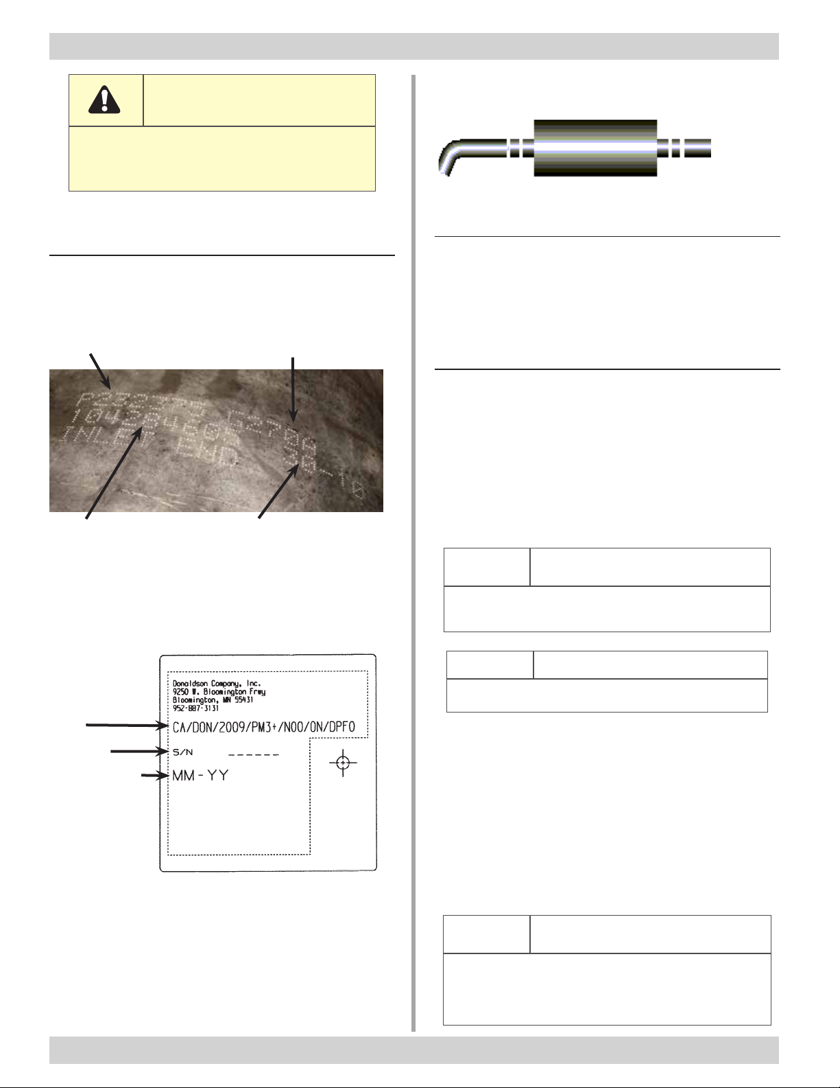
NEMA 3-Prong
Plug Style 6-30R
3. Verify that there are no nearby hazards located close to the
vehicle (i.e. electrical cords, heavy foot or vehicle traffic, etc.).
4. Verify that the muffler stack is not close to any objects that may
be damaged from the high heat of the regeneration exhaust
gases.
5. Be sure to verify that the vehicle is in park with the parking brake
applied and the wheels chocked.
6. Verify that all stored or residual energy (such as hydraulic
systems, air pressure or water pressure, etc.) is dissipated or
restrained by blocking, bleeding down, etc.
7. Notify any maintenance or operations individuals that the vehicle
is locked-out.
Lock- Out / Tag-Out
8. If there is a main power shut off to the vehicle, shut off the power
(also known as the “dead man out switch”)
9. Place a lock with marking tag on the
vehicle steering wheel (the tag should
include the name of the individual locking
out the vehicle).
10.If the vehicle is equipped with a dead man
out switch, the lock should be placed on
this switch. The tag may be placed on the
vehicle steering wheel or the dead man
out switch.
11.The lock-out/tag-out procedure shall
conform to all company standard
procedures.
Installation
This section includes separate installation procedures for the
SEF Muffler (vertical and horizontal installations), the Junction
Box, EDM and the DPF Regeneration Station. Please use
the muffler installation procedure that matches your current
muffler orientation.
The installation procedures for the EDM are in a separate
manual that ships with the EDM.
Install
Tip
Save Install Time if Disposing of the Old
Muffler and Components
It's not a good idea to reuse old exhaust components on new
retrofit emission installations. So, if your installation plan is to
discard the old components, reduce install time by using a Sawzall
to cut the muffler and old clamps out of the exhaust system.