2-2. Product Overview
DRS-0101 and DRS-0201 are state of the art modular smart servos incorporating motor,
gear reducer, control circutry and communications capability in one single package.
Both servos are capable of detecting and responding to internal changes in termerature
and voltage supply.
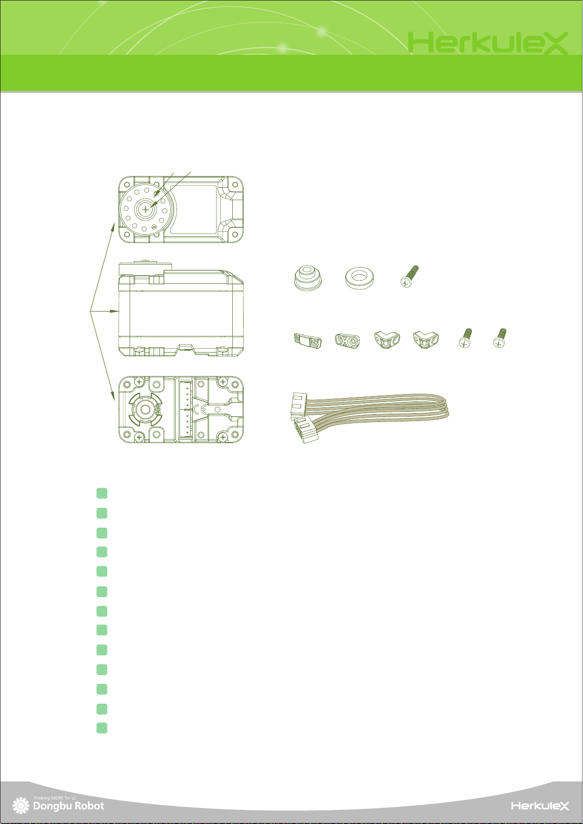
Smart Servo
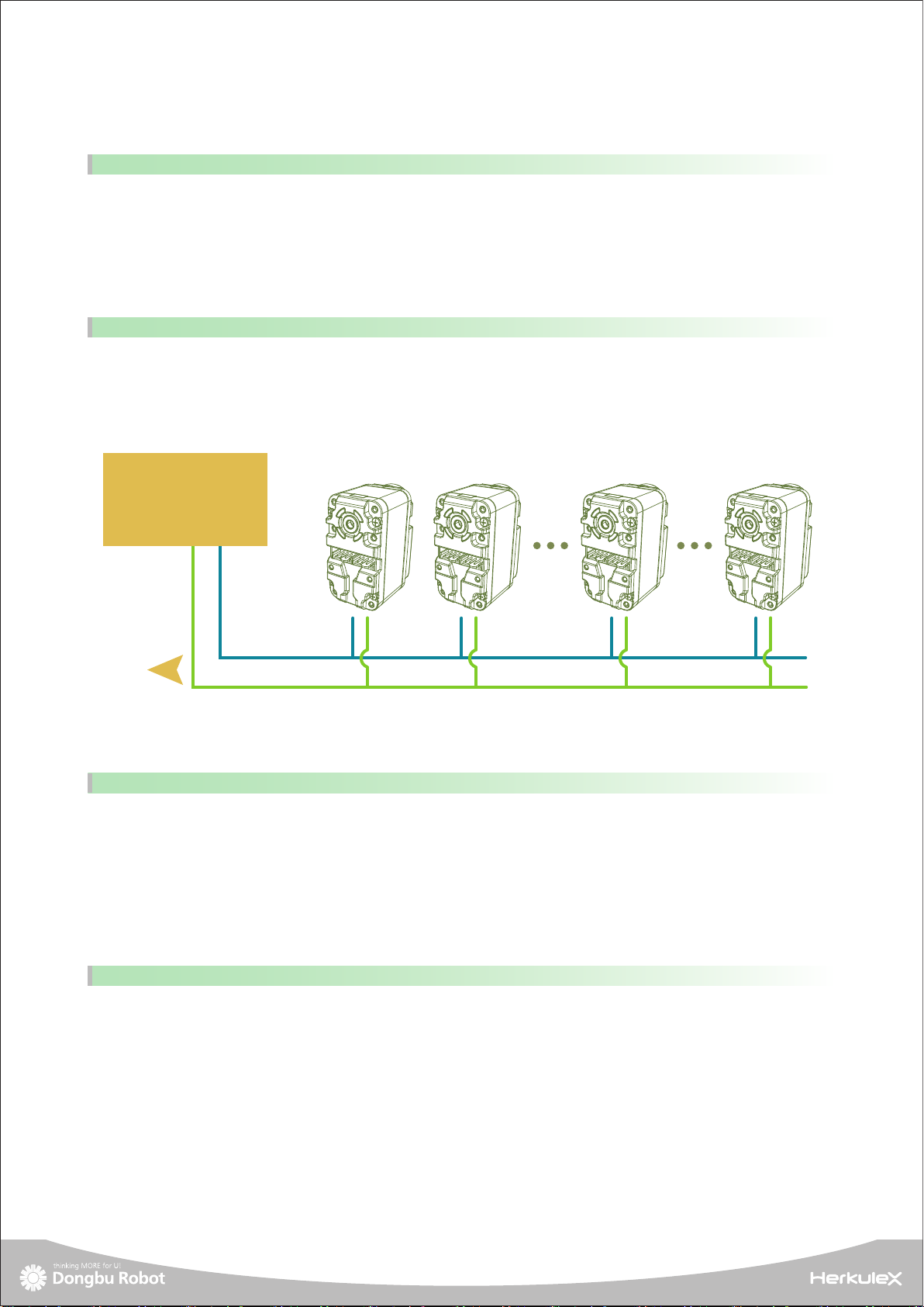
Small, light, and easy to assemble structure. Ours sevos make joint assembly an easy job with
an added advantage of simple wiring. Two connectors attached to each servo allows serial
connection as well as parallel connection if required.
Simple Assembly and Wiring
In relation to size, weight, and power requirement, our servos have the highest stall torque
in its class.
Highest Stall Torque in relation to Size and Power
Once the servo receives a movement command, it automatically creates a trapezoidal type speed
profile like the diagram below to control the position. With the servo operating according to the
acceleration/deceleration profile, it suppresses vibrations caused by the sudden acceleratiion and
deceleration as found in the square type speed profile and increases the energy efficiency while
leading to smoother movement. The servo chooses the trapezoidal type speed profile as a default
but profile could be changed according to usage to trapezoidal type, square type or triangle type.
Smooth Movement
By introducing two different models of the same size but with different torque and speed, our
customers have the choice to choose and mix and match the servos to assemble custom joints.
DRS-0101 : Stall Torque 12kgf.cm @7.4DCV [166.8 ozf.in.], Speed 0.166s/60˚ @7.4DCV
DRS-0201 : Stall Torque 24kgf.cm @7.4DCV [333.6 ozf.in.], Speed 0.147s/60˚@7.4DCV
Versatility from Two Different Models
6
Position
Time
Velocity
Time
Increasing
Accelated Period
Increasing
Accelated Period