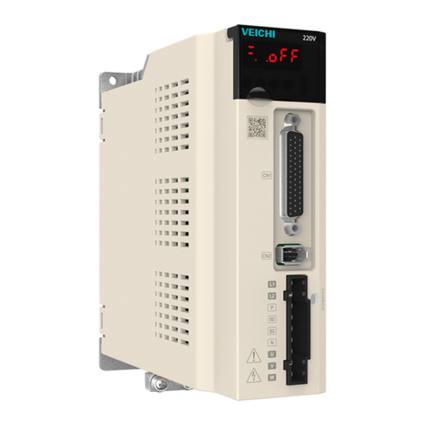
Veichi SD700 series User manual

I
Preface
Thanks for using SD700 series AC servo drive.
VEICHI SD700 series is the general purpose high performance servo drive which adopts a series of
advanced motor control algorithm and 24-bit high precision encoder, featuring high control precision, fast
tracking response, simple and convenient debugging to meet the function and performance requirements in
high-end general purpose servo applications. Rich application functions such as built-in point control
function, electronic cam, RS485 interface, CANopen interface and 16-bit analog input can provide high
reliability and high cost performance solutions for machine tools, electronic equipment, robots, textile
applications, packaging industry and etc.
This manual is delivered with equipment and only introduces safety precautions, installation and wiring,
function code table, fault diagnoses and processing, monitoring parameters and etc. For detailed function
explanations and application specifications please refer to SD700 series product instructions or consult
VEICHI company. As it is the basic guide for proper use and safe operation, please carefully read and keep
it and be sure to handle it to end users.
If any problems or special requirements, please feel free to contact our company, dealers or the customer
service center, we will provide dedicated service for you.
This manual is subject to change without notice, thanks for your kind support.

II
Safety Precautions
For safety concerns, please fully understand the safety requirements and cautions before using.
Operational Qualifications
Only professional trained people are allowed to operate the equipment. In addition, operators must
undergo professional skills training and be familiar with the equipment installation, wiring, operation and
maintenance, and can correctly respond to various emergency situations in use.
Safety Guidance
Safety regulations and warning signs come for your security. They are measures to prevent the operator
and machine system from damage. Please carefully read this manual before using and strictly observe the
regulations and warning signs while operating.
●
Correct transport, store, installation and careful operation and maintenance are important for servo
system safe operation. In transport and store process, make sure the servo system is free from
impact and vibration. It must be stored where is dry without corrosive air and conductive dust, and
the temperature bust be lower than 60℃.
●
This product carries dangerous voltage and controls driver machine with potential danger. If you
don’t abide by the regulations or requirements in this manual, there is danger of body injury even
death and machine damage.
●
Do not wire while the power is connected. Otherwise, there is danger of death for electric shock.
Before wiring, inspection, maintenance, please cut off power supply of all related equipment and
ensure main DC voltage in safe range. And operate it after 10 minutes.
●
Power line, motor line and control line must be fastened. The grounding terminal must be grounded
reliably and the grounding resistance is less than 10Ω.
●
Human body static electricity will seriously damage the internal sensitive devices. Before operation,
please follow ESD measures, or there will be danger of servo system damage.
●
As the output voltage of servo system is pulse weave, if components such as capacitors for
improving power factor or pressure-sensitive resistances for anti-thunder are installed at the output
side, please dismantle them or change to input side.

III
Content
Chapter1 Installation and Wiring ....................................................................... 1
1.1 Installation Dimensions ......................................................................... 1
1.2 Main Circuit Terminal Size ................................................................... 2
1.3 CN1 Control Terminal ........................................................................... 3
1.4 CN2 Encoder Signal Terminal .............................................................. 5
1.5 Motor Power Terminal .......................................................................... 5
1.6 CN6A/CN6B Bus Communication Terminal ..................................... 6
1.7 Keyboard Layout and Function Specifications.................................. 8
1.8 Output Port Attentions .......................................................................... 8
1.9 Brake Wiring ........................................................................................... 9
1.10 Position Control Wiring Diagram ...................................................... 10
1.11 Speed Control Wiring Diagram ......................................................... 11
1.12 Torque Control Wiring Diagram ....................................................... 12
Chapter2 Trial Run ............................................................................................. 13
2.1 JOG Trial Run ........................................................................................ 13
2.2 Bandwidth Setting(Fn303)............................................................... 13
Chapter3 Function Code List ............................................................................ 14
3.1 Pn0 Basic Control ................................................................................. 14
3.2 Pn1 Gain Parameters ........................................................................... 17
3.3 Pn2 Positional Parameters .................................................................. 23
3.4 Pn3 Speed Parameters ......................................................................... 28
3.5 Pn4 Torque Parameters ....................................................................... 30

IV
3.6 Pn5 JOG Related Parameters ............................................................ 32
3.7 Pn6 Switch Configuration Related Parameters ............................... 33
3.8 Pn7 Extension Related Parameters ................................................... 35
Chapter4 Monitoring Parameters ................................................................. 36
Chapter5 Auxiliary Function ............................................................................. 39
Chapter6 Faults and Warnings ......................................................................... 40
6.1. Fault Code ..................................................................................................... 40
6.2. Warning Code ............................................................................................... 43
Appendix I: Braking Resistor Selection ........................................................... 45

1
Chapter1 Installation and Wiring
1.1. Installation Dimensions
Dimension
Structure
Model
Dimensions(mm)
Installation dimensions (mm)
Mounting
aperture
W H D W1 W2 H1 A B
SIZE A
SD700-1R1A-**
45 168 170
\ 20 160 7.5 5 2-M4 SD700-1R8A-**
SD700-3R3A-**
SIZE B
SD700-5R5A-**
71 168 180
58 58 160 6.5 5 3-M4
SD700-7R6A-**
SD700-9R5A-**
SD700-2R5D-**
SD700-3R8D-**
SIZE C
SD700-160A-**
92.5
188 182
82.5
75 180 5 5 3-M4
SD700-6R0D-**
SD700-8R4D-**
SD700-110D-**
SIZE D
SD700-170D-**
120 260 210
100 84.5 250 10 7.
2 4-M5 SD700-240D-**
SD700-300D-**

2
Structure
Model
Dimensions
(mm)
Installation dimensions (mm)
Mounting
aperture
W H D W1 W2 H1 H2
SIZE E
SD700-500D-**
210 471 254 140 140 457 434.5 4-M6
SD700-600D-**
SIZE F
SD700-700D-**
240 558 310 176 176 544 520 4-M6
SD700-800D-**
SD700-121D-**
1.2. Main Circuit Terminal Size
L1
L2
L3
L1C
L2C
B1
B2
B3
U
V
W
+
/
Mounting aperture

3
Main circuit interface
Pins
number
Sign
name Function
1 L1
Power input of the main circuit
Please determine whether the input power is 220V or 400V according to
the nameplate
220V models: 200V ~ 240V, -15% ~ +10% 50 / 60Hz
400V models: 380V ~ 440V, -15% ~ +10% 50 / 60Hz
Note: "L3" terminal, SD700-1R1A, 1R8A, 3R3A models are single-phase
inputs without this pin
2 L2
3 L3
4 L1C
Control power input
Power input requirements same with L1, L2, L3
5 L2C
6 B1/+
Regenerative resistor connection terminal
SD700-1R1A, 1R8A, 3R3A. When regenerative braking capacity is
insufficient, connect an external regenerative resistor between B1 / + and
B2. Other models remove short wiring or short connection between B2 and
B3. Connect an external regenerative resistor between B1 / + and B2. The
external regenerative resistor need be purchased separately.
"B1 / +" terminals can be used for common DC bus positive power supply
terminals.
Note: "B3" terminal, SD700-1R1A, 1R8A, 3R3A models without this pin.
7 B2
8 B3
9 -
"-" terminal can be used for common DC bus negative power supply
terminals
10 U
Connect the U, V, W phase of the motor
11 V
12 W
13
Safe ground
1.3. CN1 Control Terminal
No.1
No.2
No.24
No.25
No.26
No.27
No.49
No.50
The appearance seen from the
arrow direction is shown below.

4

5
1.4. CN2 Encoder Signal Terminal
B
A
1
23
4
5
6
7
8
9
21
43
65
Sign Define AEnd Pins Number BEnd Pins Number
+5V
0V
SD+
SD-
PE(Shield)
1
2
5
6
1
2
5
6
Iron Shell 7
Pins Define
BAT+ 3 3
BAT- 4 4
Note: When using multi-turn absolute encoder, please pay attention to the connection of battery and serial
data.
1.5. Motor Power Terminal
视图A
3
4
12
黄绿
PE
W
V
U蓝
棕
红
A
信号定义 线芯颜色A端脚位号
40/60/80法兰电机动力线定义
U蓝
2
V棕
3
W红
4
PE 黄绿1
View A

6
PE
W
V
U
A
A D
CB
信号定义 线芯颜色A端脚位号
100/110/130/180/220法兰动力线定义
U蓝
A
V棕
B
W红
C
PE 黄绿D
1.6. CN6A/CN6B Bus Communication Terminal
引脚8
引脚1
引脚8
引脚1
CN6A
CN6B
The definition of this port is different according to different models. When you use it, you need to
confirm the model and then correspond to the definition of the interface.
The field identification bits are P: pulse type; S: standard type; C: CANopen bus type.
CN6A/CN6B Port definition
Pin No. Signal name
Function Pin No. Signal name
Function
1 CANH CAN data+ 6 -
2 CANL CAN data- 7 GND 485 signal
ground
3 CANG CAN signal 8 - -
PIN8
PIN1
PIN8
PIN1

7
ground
4 485- 485 data- shell shield shield
5 485+ 485 data+
The field identification bit is M: MECHATROLINK-II bus type.
CN6A/CN6B Port definition
Pin No.
Signal name
Function Pin No. Signal name
Function
1 SRD+ M-II data+ 6 - -
2 SRD- M-II data- 7 - -
3 - - 8 - -
4 - - shell shield shield
5 - -
The field identification bit is N: EtherCAT bus type; L: MECHATROLINK-III bus type.
CN6A/CN6B Port definition
Pin No.
Signal name
Function Pin No. Signal name
Function
1 TX+ Data
transmission +
6 RX- Data reception -
2 TX- Data
transmission -
7 - -
3 RX+ Data reception +
8 - -
4 - - shell shield shield
5 - -
Regarding the use of multiple drivers at the same time, the cascading method is CN6A in, CN6B out,
the cascading cable should be under 50cm, and the last CN6B needs to be connected to the terminating
resistor as appropriate.

8
1.7. Keyboard Layout and Function Specifications
key function
MODE/SET
Switch modes
Parameter setting confirmation button
Keys for auxiliary function execution
▲ UP It is used to select the parameter upwards or increase the value. For the multi-segment
display parameters, it can be used to switch the high, middle and low value display
▼ DOWN Used to select parameters down or decrease the value, for multi-segment display
parameters can be used to switch the high, middle and low value display
DATA/SHIFT Long press DATA/SHIFT about1 s,Used to enter or exit
Short press to move one bit to the left (when flashing)
Note: Press and hold the UP key and DOWN key at the same time to reset the servo alarm. Before
resetting the servo alarm, be sure to eliminate the cause of the alarm.
1.8. Output Port Attentions
MODE
SET
DATA

9
1.9. Brake Wiring
When servo motor is used for vertical axis situations, the brake can be used to prevent or keep the falling
speed of heavy loads when servo drive is in power off state. Wiring diagram of electromagnetic brake is
shown as below:
Electromagnetic brake must be provided with a dedicated 24V power supply, be prohibited to share
power source with control signal;
means relay coil, please note the diode direction;
Electromagnetic brakes are for holding and can not be used for normal parking;
Though electromagnetic brake has function to prevent or keep heavy objects from falling, external
braking devices are still necessary.
RY

10
1.10. Position Control Wiring Diagram

11
1.11. Speed Control Wiring Diagram

12
1.12. Torque Control Wiring Diagram

13
Chapter2 Trial Run
2.1. JOG Trial Run
The purpose of JOG trial operation is to confirm whether the servo unit and servo motor are correctly
connected and whether the servo motor is operating normally. The main parameters:
Pn500 Set the jog speed (default value is 500rpm);
Pn310 Set the jog acceleration time (default value 0ms);
Pn311 sets the jog deceleration time (default value is 0ms);
For parameter setting panel operation, please refer to Pn group parameter setting method.
Setting method of parameter Pn group Setting method of parameter Pn group:
Take the setting
method when the speed loop gain (Pn101) setting value is changed from 40.0 to 100.0 as an example.
Speed loop
gain
Auxiliary
function
Enter
setting
Any
interface
MODE/SET UP Long press
DATA/SHIFT
shift
short press
DATA/SHIFT UP inc rease
Target
value
Confirm
changes
Speed loop
gain
MODE/SET
Long press
DATA/SHIFT
Long press
DATA/SHIFT
flicker
2s
After the parameter setting is completed, execute auxiliary function Fn005, panel operation steps:
JOG
auxiliary
function
JOG ready
Any
interface
MODE/SET UP Long pres s
DATA/SHIFT
JOG
enable ON
MODE/SET UP:forward
DOWN:backward
JOG
operation
JOG ready
JOG
MODE/SET
Long press
DATA /SHIFT
Long press
DATA /SHIFT
2.2. Bandwidth Setting(Fn303)

14
Chapter3 Function Code List
3.1 Pn0 Basic Control
Function
code Parameters Range Default Unit Address
Effective
way
Pn000
Control mode selection 0~11 0 - 0x0000
RST
0-Position mode 1-Analog speed 2-Torque mode 3-Inner speed 4-inner
speed<->Analog speed
5- Inner speed <-> Position mode 6- Inner speed <-> Torque mode 7- Position
mode <-> Analog speed 8- Position mode <-> Torque mode 9- Torque mode
<-> Analog speed
10- Analog speed <->Speed mode for zero bit function 11- Position mode <->Position mode
forbidden by command pulse
Pn002
Motor rotation direction
selection 0~1 0 - 0x0002
RST
Facing the motor end face: 0- Positive counterclockwise 1- Clockwise is positive
Pn003
Default monitoring
parameters 0x0~0xfff 0xfff - 0x0003
INST
Set the monitoring parameters that are displayed by default after power-on. For the setting values,
see the monitoring parameters. 0xfff means that the monitoring parameters are not displayed and
the system status is displayed.
Pn004
Servo OFF and stop method
selection when the first type
alarm occurs
0~2 0 - 0x0004
RST
0- Stop the motor via DB 1- Stop the motor via DB,then release the DB 2- Without DB, the
motor is in free motion
Pn005
Selection of stop method for
the second type of alarm
generated by servo
0x00~0x01 0 - 0x0005
RST
0- Zero speed stop:Set the speed command to "0" and execute a rapid stop 1- Same as
Pn004 stop method
Pn006
Over travel warning detection
option 0~1 0 - 0x0006
RST
0- Over travel warning is not detected when limit 1- Over travel warning detected when
limit
Pn007
Selection of stop method
when servo over travel (OT)
occurs
0~2 0 - 0x0007
RST
Same as Pn004 stop method 1- Take the torque set by Pn053 as the maximum value, enter
the locked state after decelerating and stopping
2- Take the torque set by Pn053 as the maximum value and enter free running state after
decelerating and stopping
Pn008 Servo lock time after 0~50 0 10ms 0x0008
INST

15
electromagnetic brake
holding
When the servo motor is enabled but not running, when it is in a stopped state, when the brake (/
BK) signal and the servo ON (/ S-ON) signal are both OFF, setting this parameter can change the
brake (/ BK) signal OFF until the motor actually enter Unpowered time
Pn009
Electromagnetic brake
holding brake delay 10~100 50 10ms 0x0009
INST
When the servo motor rotates when the servo is OFF / alarm occurs / the main circuit is OFF, the
servo motor is not energized. The output time of the brake signal (/ BK) OFF can be adjusted by
this parameter and the brake holding brake delay release speed (whichever is satisfied)
Pn010
Electromagnetic brake
holding brake delay release
speed
0~10000 100 rpm 0x0010
INST
Pn012 External regenerative resistor
power 0~65535 0 10W 0x0012
INST
Pn013 External regenerative
resistance 0~65535 0 mΩ 0x0013
INST
Pn015
Overload warning value 1~100 20 % 0x0015
RST
Set this parameter to change the overload warning detection time. For example, the overload
warning detection time at the factory is 20%.
Pn016 Motor overload detection
base current derating setting
10~100 100 % 0x001
6
RST
Pn030 Reserved parameters 0~65535 0 - 0x0030
INST
Pn031 Parameter modification
operation lock 0~1 0 - 0x0031
RST
0-Allow panel to modify parameters 1- Forbid panel to modify parameters
Pn040 How to use the absolute
encoder 0~1 0 - 0x0040
RST
0- Use absolute encoder as absolute encoder 1- Use absolute encoder as incremental encoder
Function
code Parameters Range Default Unit Address
Effective
way
Pn041 Alarm / warning selection
when the absolute encoder
battery is under voltage
0~1 0 - 0x0041
RST
0- Set low battery voltage as fault 1- Set low battery voltage as warning
Pn045 Function selection under
voltage 0x00~0x02 0 - 0x0045
RST
0- No main circuit drop warning detected 1- Warning of main circuit drop detected 2-
Detection of main circuit drop warning and operate torque limitation
Pn046
Torque limit when the main
circuit voltage drops 0~100 50 % 0x0046
INST
According to the under-voltage warning, a torque limit is applied inside the servo unit, For details,
please refer to the description of "Torque Limit in Under voltage".

16
Pn047
Torque limit release time
when the main circuit voltage
drops
0~1000 100 ms 0x0047
INST
After the under voltage warning release signal, the servo unit internally controls the torque limit
value according to the set time. For details, see the description of "Main Circuit Under voltage
Torque Limit"
Pn050
Torque limit mode setting 0~3 1 - 0x0050
INST
0 –Analog torque(invalid torque mode)
1 -Maximum torque limit 1
2 -Forward torque limit 1; Reverse torque limit 2
3 -Maximum torque limit 1 when the switching value "torque limit switching" is OFF; maximum
torque limit 2 when it is ON
Pn051 Maximum torque limit 1 0~500 500 % 0x005
1
INST
Pn052 Maximum torque limit 2 0~500 500 % 0x0052
INST
Pn053 Emergency stop torque 0~800 800 % 0x0053
INST
Pn061
Panel parameter display
selection 0x00~0x01 1 - 0x0061
RST
0- Only display setting parameters 1- Show all parameters
Pn070
Encoder frequency division
pulse number 16~4194304 2048 - 0x0070
RST
According to the setting value of this parameter, the frequency of pulses from the encoder per
revolution is divided, please set according to the system specifications of the machine and the host
device
Pn072
Inverted crossover output 0~1 0 - 0x0072
RST
0- Pulse output is not inverted:When forward, A leads B 1- Pulse output reversed: when
forward, B leads A
Pn080 Local communication
address 0x00~0x7F 1 - 0x0080
RST
Pn081
485 communication baud rate
selection 0~4 1 - 0x0081
RST
0-9600bps 1-19200bps 2-38400bps 3-57600bps 4-115200bps
Pn082
485 Communication
verification method 0~5 1 - 0x0082
RST
0- No check (N,8,1) 1- Even parity (E,8,1) 2- Odd parity (O,8,1) 3- No check (N,8,2)
4- Even parity (E,8,2) 5-Odd parity (O,8,2)
Other manuals for SD700 series
3
This manual suits for next models
20
Table of contents
Other Veichi Servo Drive manuals
Popular Servo Drive manuals by other brands

Moog
Moog G400 Series installation instructions

SEW-Eurodrive
SEW-Eurodrive CMP40 - 112 operating instructions

Omron
Omron OMNUC R88D-WT15HF user manual

Vescent Photonics
Vescent Photonics D2 Series manual

Motor Power Company
Motor Power Company DMR 50-5/50 V3.0 installation guide

Pacific Scientific
Pacific Scientific OC950 EPROM installation instructions