Dongguan Xin Bao Instrument SBT401 User manual

MARTINDALE ABRASION AND PILLING TESTER
OPERATION MANUAL
** Thank you for your esteemed company to buy our products
** The operation is simple to use, but the wrong operation will cause the accidents and shorten the life of the
device or reduce its performance. Therefore, please be sure to familiarize yourself with this manual before
use.
** Please keep this manual.

CONTENTS
SAFETY INSTRUCTIONS...................................................................................................................................................... 1
WARNING................................................................................................................................................................................1
PROVISION FOR LIFTING AND CARRYING.....................................................................................................................2
OPERATING ENVIRONMENT.............................................................................................................................................. 2
CLIMATIC ENVIRONMENT................................................................................................................................................. 2
i) temp 5-55 deg celcius......................................................................................................................................................... 2
ii) humidity 30-95% RH............................................................................................................................................................2
iii) Altitude 2000m above sea level...........................................................................................................................................2
ELECTRICAL INFORMATION..............................................................................................................................................2
INSTALLATION CATEGORY AND POLLUTION DEGREE............................................................................................. 3
ELECTRICAL SUPPLY...........................................................................................................................................................3
SECTION 1 INTRODUCTION................................................................................................................................................ 4
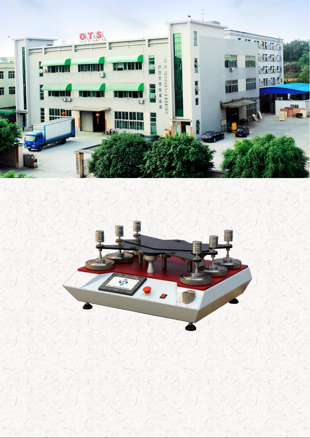
1.1 The SBT401.........................................................................................................................................................................4
1.2 Features of the SBT401....................................................................................................................................................... 4
SECTION 2 SPECIFICATIONS AND INSTALLATION.......................................................................................................4
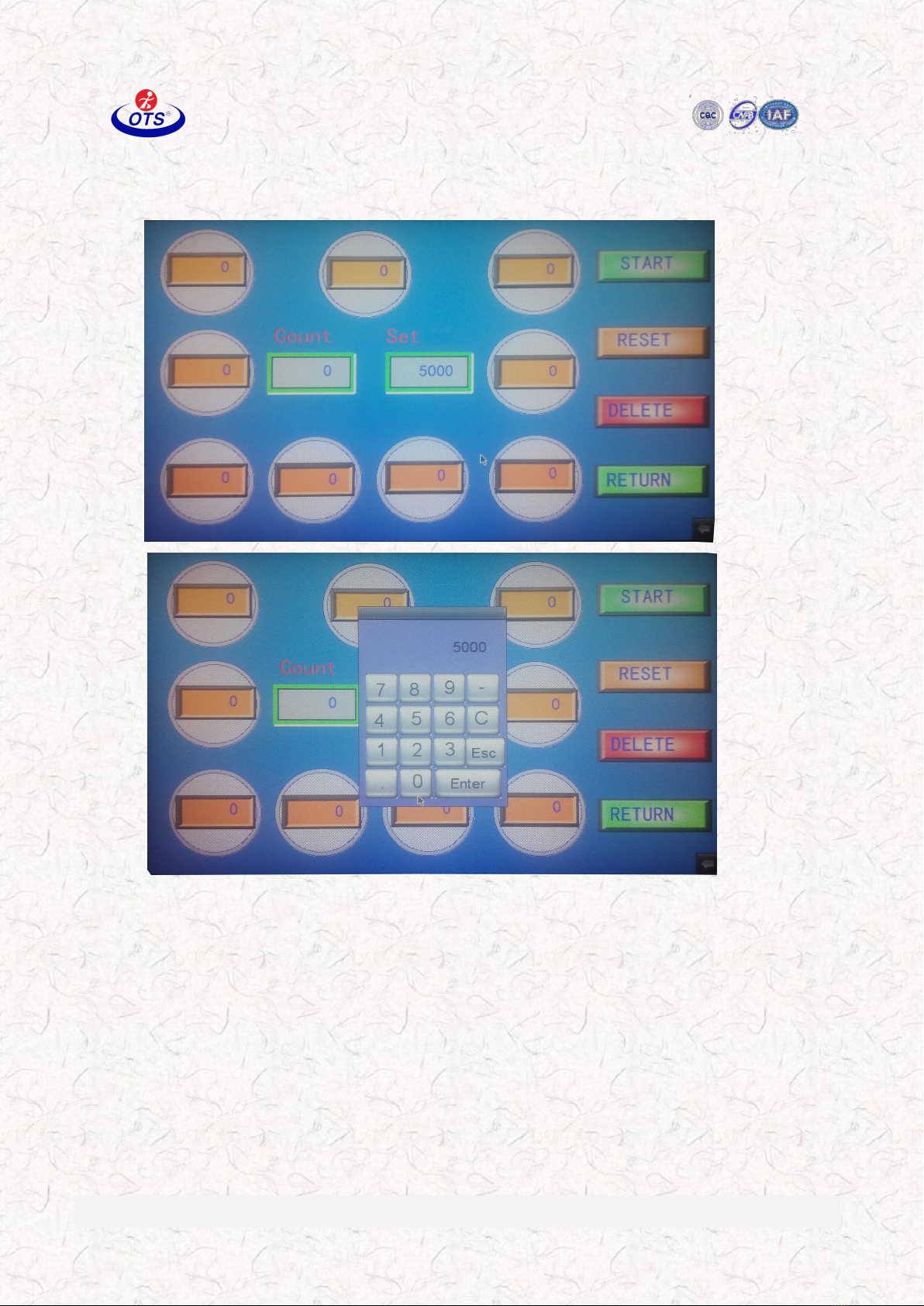
2.1 Machine Settings - ABRASION......................................................................................................................................... 4
2.2 Machine Settings - Pilling................................................................................................................................................... 4
2.3 Machine Settings at subsequent calibrations.......................................................................................................................5
NOTE 1............................................................................................................................................................................5
NOTE 2............................................................................................................................................................................5
2.4 Calibration Checks.............................................................................................................................................................. 5
SECTION 3 INSTALLATION AND ASSEMBLY................................................................................................................. 6
3.1 Assembly for Abrasion Testing...........................................................................................................................................6
3.2 Assembly for Pilling Testing...............................................................................................................................................7
SECTION 4 OPERATING INSTRUCTIONS FOR THE SBT401..........................................................................................7
4.3.1 preparation of apparatus................................................................................................................................................. 10
4.3.2 Conditioning................................................................................................................................................................... 10
SECTION 5 TESTING PROCEDURES.................................................................................................................................10
5.1 Sample preparation - Abrasion..........................................................................................................................................10
5.2 Sample preparation - Pilling..............................................................................................................................................11
5.3 Test Procedure - Abrasion................................................................................................................................................. 12
1. Determination of specimen breakdown..................................................................................................................... 12
2. Determination of Mass Loss...................................................................................................................................... 12
5.4 Test Procedure –Pilling................................................................................................................................................ 13
SECTION 6 CALIBRATION AND MAINTENANCE......................................................................................................... 14
6.1 Calibration......................................................................................................................................................................... 14
6.2 Maintenance...................................................................................................................................................................... 14

Dongguan Xin Bao Instrument Co., Ltd
Add: The 3rd Industrial Zone, Chashan Town, Dongguan. Tel: 0769-33365786 www.ots-testequipment.net
1
SAFETY INSTRUCTIONS
Due to the potential hazards associated with any electrical instrument it is important that the user is
familiar with the instructions covering the capabilities, and the operation of the instrument. The user
should ensure that all reasonable safety precautions are followed and if any doubt should seek
professional advice before proceeding.
The instrument is designed for use by suitably trained, competent personnel in a controlled working
environment and is intended for use as an abrasion and pilling tester only.
The instrument contains moving parts and while all reasonable steps have been taken to protect
personnel associated with these moving parts, incorrect or mis-use of the instrument could result in
injury.
Consideration should be given to the nature of these moving parts before setting up the instrument.
The instrument is intended to be used in a residential, commercial and light industrial environment as
laid down in EN 50081-1.
SBT cannot be held responsible for any unauthorised modifications to this unit.
WARNING
This unit contains moving parts and hazardous live voltages. Under no circumstance should the user
try to prevent or restrict the movement of parts or gain access to the internal circuitry, either
personally or with the aid of foreign bodies.
All ventilation slots must be kept clear.

Dongguan Xin Bao Instrument Co., Ltd
Add: The 3rd Industrial Zone, Chashan Town, Dongguan. Tel: 0769-33365786 www.ots-testequipment.net
2
PROVISION FOR LIFTING AND CARRYING
When unpacking or moving this unit extreme care is required, owing to its physical construction and
weight.
It is recommended that accepted lifting and carrying procedures are employed and that personnel wear
the appropriate protective equipment e.g. safety shoes.
This unit is to be move an appreciable distance/height it is recommended that it is moved via a suitable
vehicle e.g. a fork lift truck.
OPERATING ENVIRONMENT
This unit is intended to be used in a residential, commercial and light industrial environment as laid
down in BS EN 50081-1 and BS EN 50082-1.
The following list gives examples of locations in which the instrument might be located; workshops,
laboratories and service centres. Locations which are considered to be commercial or light industrial.
CLIMATIC ENVIRONMENT
The unit is intended to operate within the following conditions
i) temp 5-55 deg celcius
ii) humidity 30-95% RH
iii) Altitude 2000m above sea level.
And is intended to be stored in a temp range of –25 - +25 deg celcius.
ELECTRICAL INFORMATION
This unit complies with BS EN 61010-1 1993 safety Requirements for Electrical Equipment for
Measurement, Control and Laboratory Use.

Dongguan Xin Bao Instrument Co., Ltd
Add: The 3rd Industrial Zone, Chashan Town, Dongguan. Tel: 0769-33365786 www.ots-testequipment.net
3
INSTALLATION CATEGORY AND POLLUTION DEGREE
Installation category III
Pollution Degree 2
ELECTRICAL SUPPLY
220/240V /50Hz or 110/120V /60 Hz
Fuse requirements 5A

Dongguan Xin Bao Instrument Co., Ltd
Add: The 3rd Industrial Zone, Chashan Town, Dongguan. Tel: 0769-33365786 www.ots-testequipment.net
4
SECTION 1 INTRODUCTION
1.1 The SBT401
The SBT401 Abrasion and Pilling Tester is used to determine the abrasion and pilling resistance of all
kinds of textile structures. Samples are rubbed against abradants at low pressures and the amount of
pilling or abrasion is compared against standard parameters.
1.2 Features of the SBT401
The unique design of the SBT401 allows removal of individual sample holders for examination
without lifting the top motion plate. The equipment is supplied with individual sample counters and
pre determining batch totalisers. The equipment comes with all sample holders, a choice of loading
weights and a pressing weight to ensure correct loading of the abradant fabric.
SECTION 2 SPECIFICATIONS AND INSTALLATION
2.1 Machine Settings - ABRASION
rotational speed of each of the outer pegs
(see note 1)
47.5+/-2.5RPM
Drive ratio of outer: inner pegs
16:15
Total stroke of outer peg
60.5+/-0.25mm
Total stroke of inner peg
60.5+/-0.25mm
Face diameter of specimen holder insert
28.65+/-0.05mm
Parallelism of plate and abrading tables(see note 2)
+/- 0.05mm
Circumferential parallelism(see note 3)
+ 0.05mm
Combined total mass of specimen holder, spindle and
loading weight
599+/-2g OR
795+/-2g
2.2 Machine Settings - Pilling
Total stroke of the outer peg
24.0+/-0.5mm
Total stroke of the inner peg
24+/-0.5mm
Abrasion area of the specimen holder
64 sq cm
Mass of specimen holder and spindle (for knitted fabrics
155g+/- 1g
Mass of specimen holder, spindle and weight (for woven
415 +/- 2g

Dongguan Xin Bao Instrument Co., Ltd
Add: The 3rd Industrial Zone, Chashan Town, Dongguan. Tel: 0769-33365786 www.ots-testequipment.net
5
fabrics)
2.3 Machine Settings at subsequent calibrations
Rotational speed of each of the outer pegs
(see note 1)
47.5+/-5RPM
Lissajous figure dimensions
60.0+/-1.0mm
Face dimension of the specimen holder insert
28.65+/-0.25mm
Parallism of plate and abrading tables
(see note 2)
+/- 0.05mm
Maximum circumferential parallelism
(see note 2)
+0.05MM
Combined total mass of specimen holder, spindle and
weight
599+/-2g OR
795+/-2g
NOTE 1
The machine should be checked over a period of 5 minutes using a stopwatch.
The counter should also be checked correctly to ensure it is functioning properly.
NOTE 2
Parallelism should be measured using a dial gauge clamped in turn to each specimen bearing housing
the machine should be switched on and the maximum and minimum readings taken from a dial gauge
for each station.
The circumferential parallelism of the test piece holder assembly when inserted into each station can
be checked by means of the appropriate feeler gauges.
2.4 Calibration Checks
If the SBT401 is being used on tests where end point is defined by a change in colour, then to ensure
that the machine is correctly set, start the machine using a specimen of plain dark pigment printed
fabric.
Proceed for 7000 cycles then examine the specimen for colour change. If this is not even then the
machine is not correctly set and the machine setting listed above should be checked. It is
recommended that this is checked regularly depending on usage.
If the laboratory is using broken ends or weight loss as the end point then two reference fabrics
relevant to the work of the laboratory should be used at frequent intervals conducting the full test to
the end point.
If uneven wear is suggested between the testing positions or between machines the settings should be
checked.

Dongguan Xin Bao Instrument Co., Ltd
Add: The 3rd Industrial Zone, Chashan Town, Dongguan. Tel: 0769-33365786 www.ots-testequipment.net
6
When a new supply of abradant is obtained, the batch should be checked top ensure that the results are
consistent. Use fabrics of known performance to monitor the results of this new abradant.
SECTION 3 INSTALLATION AND ASSEMBLY
3.1 Assembly for Abrasion Testing
The machine is normally dis-assembled for shipping and should be re-assembled for abrasion testing
as follows:
1. Place the SBT401 on a firm level bench. The machine has 4 adjustable feet to allow for levelling.
2. Ensure that the three bearing support blocks are correctly positioned such that the total stroke is
60.5mm. The bearing support blocks should be in position C.
If this is not the case, then the block is moved by first unscrewing the retaining screw with the aid of
the hexagonal screw. Then lift and reposition the screw over the second peg.
Finally replace and tighten the screw.
3. Place the three metal balls into the three cups and lower the motion plate over the three bearings to
rest on the three balls.
The underside of the plate is fitted with three steel bearing plates and it is essential that the balls be
placed directly between the cups and the steel bearing plates.
It is also essential that the top motion plate is positioned correctly with respect to the casing of the
machine.
Connect to the electricity supply with the cable provided.

Dongguan Xin Bao Instrument Co., Ltd
Add: The 3rd Industrial Zone, Chashan Town, Dongguan. Tel: 0769-33365786 www.ots-testequipment.net
7
3.2 Assembly for Pilling Testing
1. Place the machine on a firm and level bench.
2. Position the bearings on the inner and outer peg drive wheels such that the total stroke of all
the pegs is reduced to 24mm .
This is achieved by moving the bearing support block to position B. It is important to note that
each block is numbered A, Bor C. Each block must therefore be fitted to the corresponding
numbered wheel drive.
To convert back for abrasion testing, the bearing support blocks are moved to position C.
3. Separate the spindles from the abrasion sample holders.
4. Push the long spindles into the pilling sample holders which are alloy with a diameter of
90mm.
5. Place the three balls into the three cups and lower the motion plate over the three bearings to
rest on the three balls.
6. The underside of the motion plate is fitted with three steel bearing plates and it is essential that
the three steel balls are placed directly between the cups and the steel bearing plates.
7. Connect to the electricity supply with the cable supplied.
SECTION 4 OPERATING INSTRUCTIONS FOR THE SBT401
4.1 Operation
1. Ensure that the machine is connected to the mains supply and the “on” switch at the front of
the machine is switched on. The power on light will illuminate.

Dongguan Xin Bao Instrument Co., Ltd
Add: The 3rd Industrial Zone, Chashan Town, Dongguan. Tel: 0769-33365786 www.ots-testequipment.net
8
2. Set the number of cycles required by using the set keys on the main counter in the centre of the
machine. Press the green button while pressing the arrow keys to do this.
3. Ensure that the batch total counter above the main counter also reads zero, if it does not then
press the RESET button to the right hand side of the display.
4. The machine is now ready to commence testing.
5. When you need to stop individual counters e.g when the end point has been reached but there
are still other samples to abrade, the following instructions should be followed :
6. Press the number of the counter which you wish to stop .
7. Press the orange button to stop this counter, when you press the green button to start, the rest
of the counters will begin but this counter which you have chosen will hold the number which
was stopped at.

Dongguan Xin Bao Instrument Co., Ltd
Add: The 3rd Industrial Zone, Chashan Town, Dongguan. Tel: 0769-33365786 www.ots-testequipment.net
9
8. If you wish to start an individual counter, press the number of the counter which you wish to
start.
4.2 General instructions
ENSURE THAT ALL MECHANICAL COMPONENTS ARE CORRECTLY POSITIONED
BEFORE PROCEEDING FURTHER.
1. Load the samples into the specimen holders
and loading the abradant onto the abradant tables .
2. Place the specimen holders onto the tables, replace the bearing housings and replace the nuts.
3. Start the test by pressing the green button.
4. The machine will continue to operate until the number of cycles reached equals the number
which has been pre set on the batch counter. At this point the machine will automatically stop.
5. If after examination a further set of cycles is required which is the same as has already been
performed, press the orange reset button and the green button and the machine will operate a
second set of rubs.
6. If after examination a further set of cycle is required which is different to number which has
already been performed, change the number on the batch total in the way previously described
and then press the green button to continue.
7. After the test has been deemed to be finished, remove the samples from the specimen holders
and mount on the template.
8. Take a note of the number of rubs conducted to get to this end point.
9. Reset all the counters in the same way as described in and carry on with the next test.
The machine may be manually stopped at any time by pressing the red button.

Dongguan Xin Bao Instrument Co., Ltd
Add: The 3rd Industrial Zone, Chashan Town, Dongguan. Tel: 0769-33365786 www.ots-testequipment.net
10
4.3 preparation of apparatus, test specimens and conditioning.
4.3.1 preparation of apparatus
1. For conducting tests for abrasion according to:
ASTM D4966、BS 2543、BS 3424-24、BS 5690、BS 8428、ISO 12947
ISO 17704、ISO 5470-2、IWTO 40、M&S P19、Next 18、SFS 4328
SN 198529、TWC 112、Volvo 1024,7122
The abrasion table should be covered with a circle of felt which is either woven or non woven
(non woven only for M&S testing). These felts are both available from SBT.
The abrasion tables should then be covered with the standard abradant fabric. This should
conform to ISO 12947–1. This abradant is available from SBT.
2. For conducting tests for pilling, the abrasion table is first covered with the standard felt as
described above and then the tables are covered with a piece of the test specimen.
3. For testing for abrasion the specimen holders should be loaded with firstly a piece of standard
foam (available from SBT) and then the sample under test.
For testing for Pilling the sample holder is firstly covered with a piece of felt and then with the sample
under test.
4.3.2 Conditioning
All samples and standard fabrics should be conditioned in the standard atmosphere for testing
All abrasion and pilling testing should be carried out in the standard atmosphere for testing:
20°C ±2°and
65% RH ± 2%.
SECTION 5 TESTING PROCEDURES
5.1 Sample preparation - Abrasion
1. After conditioning of the samples and standard fabrics, from the test fabric cut 4,6, or 9 samples
according to the capacity of the machine.
These samples should be cut 38mm diameter this can be achieved using the SBT01M cutter.
Cut the same number of samples out of the foam felt.
From the standard abradant fabric cut the required number of samples (one for each station), these
samples should be cut 140mm diameter. This can be achieved using the SBT02M cutter.
2. Take one of the specimen holders, and unscrew the bottom of the holder which will reveal a brass
nut, an insert and a holder.
3. Place the brass nut in the metal mounting device which is attached to the front of the machine.
4. Place one of the cut samples FACE DOWN in this nut.
5. Place one of the cut pieces of foam on top of this sample.
6. Place the metal insert on top of this with the flat side down.
7. Screw the holder back onto this arrangement ensuring that the sample lies parallel, this will be
achieved if pressure is applied while screwing the holder back together. Note the spindles
supplied to test for abrasion are the shorter ones. Repeat this procedure for each abrading table.

Dongguan Xin Bao Instrument Co., Ltd
Add: The 3rd Industrial Zone, Chashan Town, Dongguan. Tel: 0769-33365786 www.ots-testequipment.net
11
NOTE: ALL THE PARTS FOR ONE ABRADING STATION ARE NUMBERED. IT IS
ESSENTIAL THAT THE CORRECTLY NUMBERED PIECES ARE USED AT THE CORRECT
ABRADING STATION. e.g ALL PIECES MARKED WITH THE NUMBER 1 SHOULD ALL BE
ASSEMBLED TOGETHER AND USED AT STATION 1.
8. Remove the bearing housings from each abrading station by unscrewing the nuts and lifting the
bearing housing clear.
9. Remove the top motion plate from the machine to reveal the abrading tables.
10. At each position in turn, unscrew the three nuts and remove the clamping ring.
11. Lay a piece of cut felt, then a piece of cut abradant on each table.
12. Put the pressing weight which is the large weight with the handle on top of one of the tables and
replace the clamping ring, ensuring that it is parallel to the machine.
13. Replace the three small nuts on the clamping ring. These nuts will be level with the top of the
screws when the clamping ring is parallel. This is best achieved by gradually tightening each nut
in turn until they are all level with the top of the screws.
Note : the felt can be used for until it becomes soiled or for 50,000 rubs whichever is the sooner.
The abradant should be replaced after each test.
The foam should be replaced after each test.
14. Once all the tables and specimen holders have been loaded, lower the top plate back onto the
machine, carefully locating the slots over the bearings.
15. Place each specimen holder in the appropriate hole and replace the bearing housing with the nut to
secure.
16. Place the selected loading piece on top of the spindle (refer to the relevant standard)
17. After setting the counter according to the instructions in section 4, the machine can be switched
on and testing can commence.
5.2 Sample preparation - Pilling
(note: remember to adjust the machine settings as detailed in section 3.2 if not already done)
1. After conditioning of the standard fabrics and the test specimens, cut the required number of
samples from the test specimen the samples should be 140mm diameter. Cut two sets of these
discs, one for the pilling table and one set for the specimen holder.
2. Place the large block which comes with the pilling kit, small diameter uppermost on a table.
3. Place a rubber specimen holder ring around the outside of this device.
4. Place a 140mm disc of specimen on top of the loading device, allowing the excess material to
drape over the edge.

Dongguan Xin Bao Instrument Co., Ltd
Add: The 3rd Industrial Zone, Chashan Town, Dongguan. Tel: 0769-33365786 www.ots-testequipment.net
12
5. Place a 90mm disc in the recessed top of the loading device.
6. Invert a specimen holder and place it on top of the felt.
7. Carefully roll the rubber ring up the loading block until it locates in the groove.
8. Remove the specimen holder.
9. Note the spindles which are used for abrasion are the shorter ones which are supplied and the
spindles for pilling are the longer ones which are supplied.
10. To load the pilling tables, see table 1 to decide which abradant should be used or consult the
relevant standard being tested to.
11. In both cases the procedure detailed in section 5.1 relating to abrading tables should be used.
12. Repeat this process for all specimen holders and abrading tables.
13. Ensure that all counters are reading zero then start the test.
The method of assessing the end point will vary according to which standard is being tested to. The
following methods are suggested methods only.
5.3 Test Procedure - Abrasion
1. Determination of specimen breakdown.
Normally four specimens are tested, one in each of the abrading stations.
Inspect the specimens at regular intervals without removing the specimens from the holders,
A magnifying glass or microscope will normally be required for this examination.
The end point is deemed to have been reached when the specimen has at least two threads broken in
the test area.
This should be carried out until all the specimens have reached this end point
Report the individual results as well as the mean result.
Replace the rubbed specimens in the holes on the mounted report sheet.
Note once a specimen has reached the end point it is not necessary to replace this holder for the
continued running of the test.
2. Determination of Mass Loss
See table 1 to determine at which intervals the mass loss should be determined.

Dongguan Xin Bao Instrument Co., Ltd
Add: The 3rd Industrial Zone, Chashan Town, Dongguan. Tel: 0769-33365786 www.ots-testequipment.net
13
Weigh all specimens before and after abrasion at each of the pre determined intervals.
Draw a graph of no. of rubs against mass loss.
(see also ISO 12947 part 3). For further details of the test method)
TABLE 1
TEST SERIES
NO. OF RUBS AT WHICH
SPECIMEN BREAKDOWN
OCCURS
DETERMINATION OF MASS LOSS AT
FOLLOWING NUMBER OF RUBS
A
1000\
100, 250, 500, 750, 100, (1250)
B
>1000 5000
500, 750, 1000, 2500,5000, (7500)
C
>5000 10000
1000, 2500, 5000, 7500, 10000, (15000)
D
>1000025000
5000, 7500, 10000, 15000, 25000, (40000)
E
>25000 50000
10000, 15000, 25000, 40000, 50000,(75000)
F
>50000 100000
10000, 25000, 50000, 75000,100000, (125000)
G
>100000
25000, 50000, 75000, 100000, (125000)
The values in brackets should be agreed upon between the interested parties.
5.4 Test Procedure –Pilling
Consult table 2 to determine which accessories should be used to conduct the Pilling test.
Pairs of samples are rubbed together for periods which again vary according to the test method being
used (see Swiss Standard SN 198525) for further details.
Table 2
0.65kPa
For woven and all upholstery including
(knitted) when following SN 198525
Swiss pilling kit with pilling weight
0.25kPa
For knitted fabric (excluding upholstery when
testing to SN198525
Swiss pilling kit without the pilling
weight
Table 3
First pair
125 cycles
Second pair
500cycles
Third pair
2000 cycles
The three pairs of samples are used to provide examples of nil, slight and moderate levels of pilling
required in the assessment procedure described below.
When carrying out the test on the third pair it is important to stop the machine after every 500 cycles
and lightly brush away any loose fibres which may have gathered on the test surface.
The degree of Pilling should be assessed using the following 5 point scale.
5
Zero or only very slight pilling
4
Slight pilling
3
Moderate pilling
2
Severe pilling
1
Very severe pilling
When the appearance falls between two of the descriptions given above half values may be given. A

Dongguan Xin Bao Instrument Co., Ltd
Add: The 3rd Industrial Zone, Chashan Town, Dongguan. Tel: 0769-33365786 www.ots-testequipment.net
14
set of photographs is also available from SBT which are mounted in an assessment viewer to enable
the specimens to be more consistently rated.
SECTION 6 CALIBRATION AND MAINTENANCE
6.1 Calibration
1. The motion plate and abradant plate should be parallel. Insert a dial gauge through the sample
holder bearing and inch the top plate.
The needle movement over the dial gauge should be within ±0.05mm over the whole surfaces
of the abradant tables (with the abradant cloth removed).
2. Assemble each sample holder complete with the weight and place each one in position on the
appropriate table.
Use a feeler gauge to check for any gap between the face of the specimen holder and the table.
3. to adjust tables, slacken the central screw and adjust as appropriate using the three jacking
screws located on the main deck plate.
When complete, re tighten the central securing screw.
4. to adjust the motion plate, slacken the locking nut fitted to the stem of the three ball carrying
cups rotate the cups to the correct height and re tighten the locking nuts.
6.2 Maintenance
1. The motion plate slides should be lightly smeared with grease.
2. The ball cups should be lightly oiled as required.
Table of contents
Other Dongguan Xin Bao Instrument Test Equipment manuals
Popular Test Equipment manuals by other brands

Keithley
Keithley Interactive SourceMeter 2450 Declassification and security instructions

VOH
VOH Wheeltest III user manual

GDZX
GDZX ZXJS-I manual

Agilent Technologies
Agilent Technologies InfiniiVision 5000 Series user guide

ANSMANN
ANSMANN KFZ-POWER-CHECK operating instructions

Artel
Artel PCS quick start guide