manuals.online logo
Brands
  1. Home
  2. •
  3. Brands
  4. •
  5. GW Instek
  6. •
  7. Test Equipment
  8. •
  9. GW Instek LCR-05A User manual

GW Instek LCR-05A User manual

Other GW Instek Test Equipment manuals

GW Instek GDS-820 Programming Owner's manual

GW Instek

GW Instek GDS-820 Programming Owner's manual

GW Instek C-1200 User manual

GW Instek

GW Instek C-1200 User manual

GW Instek GOS-630FC User manual

GW Instek

GW Instek GOS-630FC User manual

GW Instek GDS-3000 Series User manual

GW Instek

GW Instek GDS-3000 Series User manual

GW Instek GDS-3152 User manual

GW Instek

GW Instek GDS-3152 User manual

GW Instek GUT-6000A User manual

GW Instek

GW Instek GUT-6000A User manual

GW Instek GDS-2000 Series User manual

GW Instek

GW Instek GDS-2000 Series User manual

GW Instek MSO-2000EA User manual

GW Instek

GW Instek MSO-2000EA User manual

GW Instek MDO-2000A Series User manual

GW Instek

GW Instek MDO-2000A Series User manual

GW Instek GPT-9800 User manual

GW Instek

GW Instek GPT-9800 User manual

GW Instek GDS-800 Series User manual

GW Instek

GW Instek GDS-800 Series User manual

GW Instek PEL-2000 Series User manual

GW Instek

GW Instek PEL-2000 Series User manual

GW Instek GDS-1000A-U Series User manual

GW Instek

GW Instek GDS-1000A-U Series User manual

GW Instek GPT-700A Series User manual

GW Instek

GW Instek GPT-700A Series User manual

GW Instek GPT-9801 User manual

GW Instek

GW Instek GPT-9801 User manual

GW Instek PEL-2002 User manual

GW Instek

GW Instek PEL-2002 User manual

GW Instek GUT-6600A User manual

GW Instek

GW Instek GUT-6600A User manual

GW Instek GCT-9040 User manual

GW Instek

GW Instek GCT-9040 User manual

GW Instek GDS-200 Series User manual

GW Instek

GW Instek GDS-200 Series User manual

GW Instek GDS-1000A Series User manual

GW Instek

GW Instek GDS-1000A Series User manual

GW Instek GOS-6103C User manual

GW Instek

GW Instek GOS-6103C User manual

GW Instek GDS-1062A User manual

GW Instek

GW Instek GDS-1062A User manual

GW Instek GDS-3152 User manual

GW Instek

GW Instek GDS-3152 User manual

GW Instek GDS-1000B Series Owner's manual

GW Instek

GW Instek GDS-1000B Series Owner's manual

Popular Test Equipment manuals by other brands

Ambit P.F. Series instruction manual

Ambit

Ambit P.F. Series instruction manual

Megger BMM500 Series user guide

Megger

Megger BMM500 Series user guide

RJG Lynx Sensor Tester operating instructions

RJG

RJG Lynx Sensor Tester operating instructions

Mark-10 TT02 Series user guide

Mark-10

Mark-10 TT02 Series user guide

Martel 3001 Operator's manual

Martel

Martel 3001 Operator's manual

ElproSys DiagProg4 instruction manual

ElproSys

ElproSys DiagProg4 instruction manual

Redtech TRAILERteck T05 user manual

Redtech

Redtech TRAILERteck T05 user manual

Venmar AVS Constructo 1.0 HRV user guide

Venmar

Venmar AVS Constructo 1.0 HRV user guide

Test Instrument Solutions SafetyPAT operating manual

Test Instrument Solutions

Test Instrument Solutions SafetyPAT operating manual

Hanna Instruments HI 38078 instruction manual

Hanna Instruments

Hanna Instruments HI 38078 instruction manual

Kistler 5495C Series instruction manual

Kistler

Kistler 5495C Series instruction manual

Waygate Technologies DM5E Basic quick start guide

Waygate Technologies

Waygate Technologies DM5E Basic quick start guide

StoneL DeviceNet CK464002A manual

StoneL

StoneL DeviceNet CK464002A manual

Seica RAPID 220 Site preparation guide

Seica

Seica RAPID 220 Site preparation guide

Kingfisher KI7400 Series Training manual

Kingfisher

Kingfisher KI7400 Series Training manual

Kurth Electronic CCTS-03 operating manual

Kurth Electronic

Kurth Electronic CCTS-03 operating manual

SMART KANAAD SBT XTREME 3G Series user manual

SMART

SMART KANAAD SBT XTREME 3G Series user manual

Agilent Technologies BERT Serial Getting started

Agilent Technologies

Agilent Technologies BERT Serial Getting started

manuals.online logo
manuals.online logoBrands
  • About & Mission
  • Contact us
  • Privacy Policy
  • Terms and Conditions

Copyright 2025 Manuals.Online. All Rights Reserved.

Test Fixture
LCR-05A
QUICK START GUIDE
GW INSTEK PART NO. 82CR-05A00M01
ISO-9001 CERTIFIED MANUFACTURER
This manual contains proprietary information, which is protected by
copyright. All rights are reserved. No part of this manual may be
photocopied, reproduced or translated to another language without
prior written consent of Good Will Corporation.
The information in this manual was correct at the time of printing.
However, Good Will continues to improve its products and therefore
reserves the right to change the specifications, equipment, and
maintenance procedures at any time without notice.
Good Will Instrument Co., Ltd. No. 7-1, Jhongsing Rd., Tucheng Dist., New Taipei City
236, Taiwan.
①
OVERVIEW
The LCR-05A Test Fixture for axial & radial leaded components.
Specifications
Model LCR-05A
DUT Connector 4-Terminal
Measurement Frequency DC to 30MHz
Maximum Voltage ±45V Peak max.(AC+DC)
Application size See figure below with electrode size
Dimensions: 98W x 25H x 65D mm
Weight 246g
Operating Environment 0~50˚C, <70%RH
Additional error (with open & short correction) f:[MHz]
Proportional error f
≦
20MHz 0.275 × (f/10)2[
%
]
Proportional error f>20MHz 5.5 × (f/100) [%]
Open repeatability 0.002 + 10 × (f/100) [μS]
Short repeatability 2 + 600 × (f/100) [mΩ]
②
Fixture Overview

Index Item Description Quantity
1 Test Fixture Main Body The main body of test fixture 1
2 Electrode Test terminals that connect with
DUT (Device Under Test) 4
3 Adjusting Screw To adjust the scale of Electrode
openings at both sides 2
4 Short-Circuit Jumper
Box To place the short-circuit jumper 1
5 BNC Measuring terminals that connect
with instruments 4
6 Fixing Handles
It fastens or loosens terminals
between
BNC and instrument. Turn
right to fix, whilst turn left to loosen
2
7 STD LOAD Standard resistor (100Ω) 1
8 Short-Circuit Jumper The short-circuit Jumper 1
9 L-Shape Bracket
It can be fixed to test fixture main
body to raise stability when test
fixture is under test, further
reducing BNC improper force (The
screws are fixed on the test fixture
main body by default)
1
③
INSTALLATION
1. Turn the both fixing handles of BNC terminals from LCR-05A test fixture
toward left side until the gap of BCN external sleeve faces upward.
2. Align the gap with the salient point of BNC terminal from LCR test
instrument and insert it firmly into place. Turn the both fixing handles of
BNC terminals from LCR-05A
test fixture toward right side until the external
sleeve of BCN is fixed stably into place.
Note: When the L-shape bracket is employed, take off the nut from the
ground terminal prior to test fixture installation. Follow the steps
above for proper installation followed by fastening the nut so that the
test fixture can be held tightly when DUT is inserted.
Note: Refer to the pictures below for details of L-shape bracket installation.
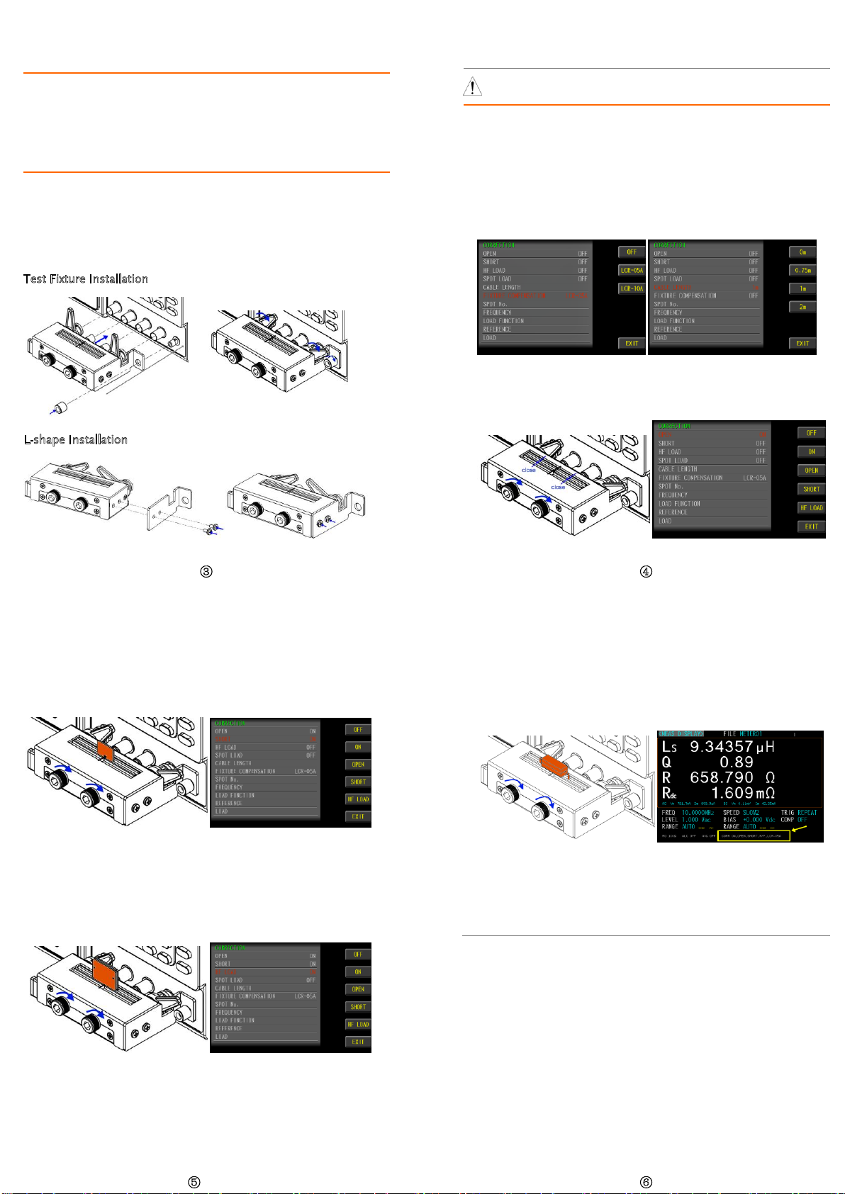
Test Fixture Installation
L-shape Installation
④
MEASUREMENT
WARNING Before measurement, be sure to read the operating
instructions to avoid danger.
1. Set measuring conditions with parameters, and install LCR-05A test fixture.
2. Execute the CORRECTION mode. Set LCR-05A for the FIXTURE
COMPENSATION item in order to execute LCR-05A parameter
compensation, by which the CABLE LENGTH item will be unavailable.
On the other hand, when extension cable is wired with LCR-05A for
measurement, it is required to disable the FIXTURE COMPENSATION
item (OFF) and instead select an appropriate option for CABLE LENGTH
corresponding to the employed cable.
3. Fasten the adjusting screws clockwise to make the Electrodes tightly
close. Execute the OPEN CORRECTION and the OPEN item will change
from OFF to ON.
⑤
4. Loosen the adjusting screws counter-clockwise to make the Electrodes
open. Insert the short-circuit jumper into the Electrodes followed by
fastening the screws. Subtly adjust the Electrodes to clamp the short-
circuit jumper tightly. Execute the SHORT CORRECTION and the SHORT
item will change from OFF to ON.
5. It is suggested to execute HF LOAD calibration when test frequency is
greater than 3MHz. Loosen the adjusting screws counter-clockwise to
make the Electrodes open. Insert the STD-LOAD into the Electrodes
followed by fastening the screws. Subtly adjust the Electrodes to clamp
the STD-LOAD tightly. Execute the HF LOAD CORRECTION and the HF
LOAD item will change from OFF to ON.
⑥
6. Loosen the adjusting screws counter-clockwise to make the Electrodes
open. Insert the DUT into the Electrodes followed by fastening the screws.
Subtly adjust the Electrodes to clamp the DUT tightly and it is now ready
for measurement. The latest calibration status will be shown in the
bottom of the LCD display (item and measuring cable length or test
fixture model).
7.
Remove the component from the test fixture.
Note: It is required to place DUT into the test fixture in exactly vertical way
without any tilt, skew or wobble. Do Not fasten the adjusting screws
overly in case of thread stripped
and over compression on DUT. Also, do
Not overly loosen the screws in case of accidental drop out of screws.