WHALETEQ CMRR 3.0E User manual

CMRR 3.0E | User Manual
WHALETEQ
Common Mode Rejection Ratio Tester
For IEC80601-2-26:2019
CMRR 3.0E User Manual
(Revision 2020-09-03)
PC Software Version V1.0.6.9

CMRR 3.0E | User Manual
2
Copyright (c) 2013-2020, All Rights Reserved.
WhaleTeq Co. LTD
No part of this publication may be reproduced, transmitted, transcribed, stored in a retrieval system, or
translated into any language or computer language, in any form, or by any means, electronic, mechanical,
magnetic, optical, chemical, manual or otherwise, without the prior written permission of WhaleTeq Co.
LTD.
Disclaimer
WhaleTeq Co. LTD. provides this document and the programs "as is" without warranty of any kind, either
expressed or implied, including, but not limited to, the implied warranties of merchantability or fitness for
a particular purpose.
This document could contain technical inaccuracies or typographical errors. Changes are periodically
made to the information herein; these changes will be incorporated in future revisions of this document.
WhaleTeq Co. LTD. is under no obligation to notify any person of the changes.
The following trademarks are used in this document:
is a registered trademark of WhaleTeq Co. LTD
All other trademarks or trade names are property of their respective holders.

CMRR 3.0E | User Manual
3
Table of Contents
1Introduction 5
2Electrical Diagram 5
3Set Up a Noise Free Test Environment 6
3.1 Reduce environmental noise and connect outer shielding to the ground plane. 6
3.2 Shielding Covers for the Electrode Cables 7
4Principle of the CMRR test 8
4.1 Common mode rejection ratio explained 8
4.2 Test equipment 8
5Panel Function 9
5.1 Upper Panel 9
5.1.1 LCD Touch Screen 10
5.1.2 [Coarse] Knob 10
5.1.3 [Fine] Knob 10
5.1.4 70.71 Vrms Switch 11
5.2 Front Panel 11
5.2.1 Tapped Hole 11
5.2.2 USB Connector 11
5.2.3 [DC 12V] Terminal 11
5.2.4 Power Switch 12
5.2.5 [Vc] Terminal 12
5.2.6 [Vs] Terminal 12
5.2.7 [Monitor] Terminal 12
5.2.8 Grounding Terminal 12
5.3 Right Panel 12
5.3.1 [CM Point] Terminal 13
5.3.2 RA/LA/LL/RL/V1~V6 Electrode Terminals 13
6Operation 13
6.1 Stand-alone Operation 13
6.1.1 Touch Screen for Setting Different Parameters 13
6.1.2 Test Exemplification 16
6.2 PC Software Operation 17
6.2.1 CMRR 3.0E PC Software 17
6.2.2 CMRR 3.0E Assistant Software 18
7Caution 21
7.1 Baseline noise test 21
7.2 Battery power consumption for DC offset function 21
7.3 Vs voltage drop with the multimeter of 1MΩ input impedance 21
7.4 QC PASS Label 21
8CMRR 3.0E Specifications 22

CMRR 3.0E | User Manual
5
1Introduction
CMRR 3.0E uses double shielding construction according to IEC80601-2-26:2019 standard and includes
the following features
-Built-in sine wave signal generator. CMRR 3.0E provides 2 Vrms signal output required by
IEC80601-2-26:2019 and the frequencies covers 50 Hz, 60 Hz, 100 Hz, and 120Hz.
-Use coarse and fine knobs to adjust the variable capacitance value Ct. The sum of Ct and Cx (stray
capacitance) shall be 100pF.
-Built-in voltage measuring circuit for Vs and Vc voltages. Vs value indicates the signal voltage
generated by built-in sine wave generator and Vc value is the voltage behind 100 pF capacitive
voltage divider. User can easily confirm whether Vc value is half of Vs value while adjusting
capacitor value Ct.
-Offer a precise and stable ± 150mV DC power supply.
-Provide imbalance impendence and DC offset options. Use MCU to control relay to switch on and
off within the isolated circuit.
-Provide output terminals of Vs, Vc, Monitor and GND for monitoring applied voltages in the
calibration process. For Monitor output terminal, it’s designed to confirm voltage value Vc. Due
to the high impedance brought by 100 pF at 50/60/100/120hz, this causes typical multimeters
being not able to measure precisely. Besides, it requires non-load output voltage at 10 Vrms in
certain IEC standards. Therefore, WhaleTeq CMRR 3.0E uses 11:1 (110MΩ:10MΩ)voltage
divider and designated circuit design as the best compromise solution for accuracy, circuit load,
noise and input impedance of typical multimeters. Therefore, the Monitor terminal voltage shall
be Vc/11 Vrms.
-CMRR 3.0E is equipped with a touch screen which enables to adjust and display all required test
parameters on the screen.
-Via USB interface connection, CMRR 3.0E can be controlled by PC software or SDK (Software
Development Kit).
-CMRR Standard Assistant software simplifies medical standards with test procedures, test options
and pass criteria. User can easily select and click to conduct the required tests.
2Electrical Diagram
Figure 2-1 indicates the electrical diagram of CMRR 3.0E. Ct is the adjustable variable capacitance and Cx
is the stray capacitance between inner shield and outer shield.

CMRR 3.0E | User Manual
6
Figure 2-1, CMRR 3.0E Electrical Diagram
Item:
1Signal generator
2Internal connection wires
2A Electrode terminals
3±150 mV DC Power Source
4Inner Shield
5Outer Shield
6Isolated control circuit (electrode)
6A isolated control circuit (signal generator)
7Voltage monitor (Vs, Vc)
8User control unit (Switch, USB)
9MCU
10 LCD display module
*6 and 6A are the isolated circuits for isolating noises existed in power source and signal.
3Set Up a Noise Free Test Environment
3.1 Reduce environmental noise and connect outer shielding to the ground plane.
It’s a must to reduce noise when testing EEG. Please refer to the below description for reducing
environmental noise.

CMRR 3.0E | User Manual
7
(1) Place a metal sheet or a metal bench under ECG DUT and CMRR 3.0E
(2) Connect GND terminal (outer shielding point) of CMRR 3.0E to the metal sheet or the metal
bench.
(3) Connect the metal frame of EEG DUT to the metal sheet or the metal bench.
(4) Tester shall keep distance from the test system, to prevent from body capacitance effect. Else,
tester shall touch the metal sheet or the metal bench to connect to the common ground plane.
Figure. 3-1, Set-up CMRR 3.0E Test Environment
3.2 Shielding Covers for the Electrode Cables
(1) Please fasten the bottom shielding cover to the right-side panel of CMRR 3.0E for reducing main
frequency interference. (see Figure.3-2)
Figure. 3-2, CMRR 3.0E with bottom shielding cover
(2) As the bottom shielding cover is connected to Vc, Vc would be unstable due to the outer noise.
When Vs is 2V (Vc=1V), Vc has the possibility to exceed 1% tolerance. At the time, please fasten the
top shielding cover with CMRR 3.0E, to control Vc voltage within 1% tolerance. (See Figure. 3-2)

CMRR 3.0E | User Manual
8
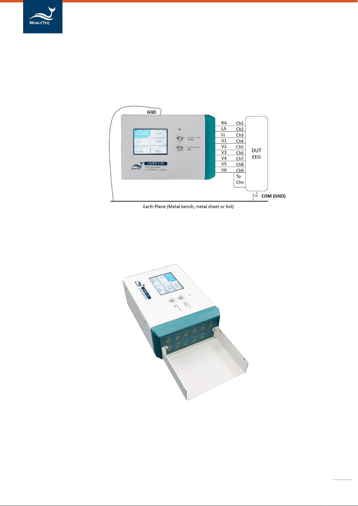
Fig. 3-3, CMRR 3.0E with top shielding cover
4Principle of the CMRR test
4.1 Common mode rejection ratio explained
A perfect device measuring a differential voltage should not respond to the level of common mode
voltage which appears at both inputs. For example, a multimeter where the positive terminal is
+100.017V and the negative terminal is +100.001V should theoretically indicate measured voltage of
16mV.
In practice, due to slight differences in resistances used in differential amplifiers, some of the common
mode voltage will come through as an error. The common mode rejection ratio or CMRR indicates the
ability of the equipment to reject these common mode voltages.
A scale of dB is normally used as the ratio can range from as low as 100 up to 100,000 (40dB to 100dB). A
CMRR of 60dB indicates a ratio of 1000, and means that common mode voltages will be reduce by a
factor of 1000. In the example given, equipment with a CMRR of 60dB would have the common voltage
(+100V) reduced to 10mV, still a significant error relative to the differential voltage of 16mV. In practice,
the common mode voltage is usually not more than 10 times the differential voltage, so a CMRR of 60dB
would only result in a 0.1% error.
The most common source of common mode noise is mains voltages, i.e. 50/60Hz. Thus, CMRR in meters
is usually specified at these frequencies. But it is important to note that CMRR varies with frequency.
Common mode rejection also varies with the impedance of the source, or more specifically the
impedance imbalance, as the imbalance also upsets the measurement circuit. CMRR for multimeters is
typically specified with a 1kΩ imbalance.
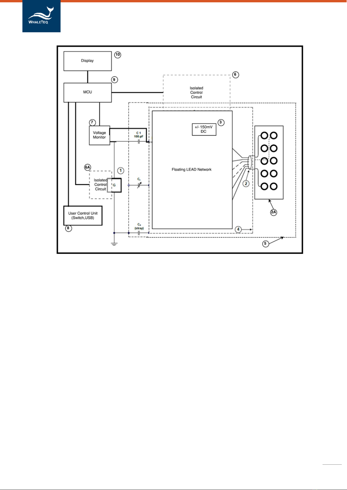
4.2 Test equipment
Refer to the standard for the test circuit.
From a testing point of view the series 100pF introduces significant complications, as it represents a very
high impedance of about 30MΩ at 50/60Hz. This means that attempts to measure the applied voltage
(10Vrms) with a normal multimeter will fail, because the meter has around 10MΩ input impedance. It is
possible to use 1000:1 HV probe with an oscilloscope (100MΩ/3pF), but noise and other errors can be
large. Even 100MΩ/3pF will load the circuit, so the voltage will change (increase) by about 5% after the
HV probe is removed, which should be accounted for if such probes are used.
WhaleTeq CMRR 3.0E equipment resolved the difficulty in measuring Vc by using 110MΩ/10MΩ 11:1

CMRR 3.0E | User Manual
9
voltage divider and voltage measuring circuit to measure the common mode voltage Vc after 100pF
automatically.
The 100pF also creates a problem with the position of the patient cable. If the cable is allowed to sit on an
earthed plane, the stray capacitance can be enough to provide additional loading and reduce the actual
common mode voltage. This stray capacitance is highly variable and thus can impact the test. For
conservative tests, the cable should be supported off the earth plane, but remain above the earth plane
in order to minimize noise.
A sine wave signal generator is built in CMRR 3.0E. It offers 2 Vrms signal required by EEG standard
(IEC80601-2-26:2019) and the test setup becomes easy and time-saving.
Common mode rejection is also dependent on imbalance impedance test. For this reason, the test also
introduces an imbalance of 10kΩ//47nF in one lead only. Experience from tests indicates that without this
imbalance, there is usually no visible indication on the EEG, but with the imbalance readings typically
range between 3-7mm (0.3 ~ 0.7mVpp). This suggests that the value of imbalance impedance is critical
for the tests. Although the diagram in the standard shows all switches open, for the purpose of the test,
all switches should be closed except the lead being tested and some tests are in the opposite settings
instead. CMRR 3.0E uses MCU to control the relay switch, which makes it easy to set up various balance
and imbalance impedance.
IEC 80601-2-26:2019 requires a DC offset of ±150mV. CMRR 3.0E uses MCU to control +/- 150mV DC
offset and it is easy to set +/- 150mV DC offset with different imbalanced impedance electrodes. The
CMRR 3.0E DC offset is supplied by an internal battery. The lifetime of this battery is estimated to be at
more than 40 hours under continuous use. Therefore, its time in service should be long enough for tests
that only last a few seconds each time. In case there is a need to replace the battery, user just need to
remove the battery cover at the bottom of CMRR 3.0E and replace with a new battery.
5Panel Function
5.1 Upper Panel
The upper panel of CMRR 3.0E is shown in figure 5-1. Please see below introductions for the functions of
LCD touch screen and knobs:

CMRR 3.0E | User Manual
10
Figure 5-1, the upper panel of CMRR 3.0E
The whole CMRR 3.0E operation can be done with the knobs on the upper panel. All of the parameters
can be shown on the LCD touch screen.
5.1.1 LCD Touch Screen
The LCD touch screen displays all the options and test parameters.
The main page of LCD touch screen is used for select functions of “Standard”, “Voltage”, “Frequency”,
“Impedance” and “DC Offset”by touching the area.
Once selected, the area shall be with light blue background display. User can click the up arrow button or
the down arrow button to switch between different options. For example, you can click the arrow bottom
to quickly switch [Off], [20], [2.828], [0.5] and [2.0] Vrms for Supply Voltage under [Manual] standard.
Otherwise, user can double click the function to have all the options shown in a separated page.
5.1.2 [Coarse] Knob
Located at the right side of the LCD display, it is used to tune adjustable capacitance Ct to make its sum
with stray capacitance Cx into 100pF. The coarse scale ranges by tens of pF, and the fine scale ranges by
pFs.
5.1.3 [Fine] Knob
Located at the right side of the LCD display, it is used to tune adjustable capacitance Ct to make its sum
with stray capacitance Cx into 100pF. The fine scale ranges by pFs.

CMRR 3.0E | User Manual
11
5.1.4 70.71 Vrms Switch
A hole located above [Coarse] knob. Pressing the switch in the hole with a small-size screwdriver for 6
seconds launches the hidden 70.71 Vrms voltage setting function. When outputting 70.71 Vrms signal,
user can press the hidden switch again or directly turn off the power switch, to stop the high voltage
output.
Under the manual mode, the [70.71 Vrms] option can be selected to test a higher CMRR value.
5.2 Front Panel
The front panel of CMRR 3.0E is shown in figure 5-2. Please see instruction to each terminal as below:
Figure 5-2, the front panel of CMRR 3.0E
Connectors on the front panel are mainly used for power supply, USB connection and calibration.
5.2.1 Tapped Hole
The front and back panels each has two tapped holes for fastening the shielding cover or the shielding
case which is a CMRR 3.0E optional accessory.
5.2.2 USB Connector
Once connected to a PC, CMRR 3.0E can be commanded by CMRR 3.0E PC software or CMRR 3.0E SDK
(Software Development Kit).
5.2.3 [DC 12V] Terminal

CMRR 3.0E | User Manual
12
It connects the DC 12V power supply bundled with CMRR 3.0E to provide the power required by
operation.
5.2.4 Power Switch
It turns on or off the mains supply of DC 12V power supply.
5.2.5 [Vc] Terminal
It connects the common mode point inside CMRR 3.0E to Vc terminal directly. This is intended for use in
equipment calibration.
5.2.6 [Vs] Terminal
The voltage output of CMRR 3.0E built-in sine wave signal generator. This is intended for use in
equipment calibration.
5.2.7 [Monitor] Terminal
The output terminal of inner common mode point after it passes through 11:1 voltage divider. It
measures the voltage of Vc decayed by a factor of 11 directly. This is intended for use in equipment
calibration.
5.2.8 Grounding Terminal
Outer shield grounding that connects the metal sheet in figure 3-1 in tests to reduce noises.
5.3 Right Panel
The right panel of CMRR 3.0E is shown in figure 5-3. It is mainly used to connect each electrodes of EEG.
Figure 5-3, the right panel of CMRR 3.0E

CMRR 3.0E | User Manual
13
5.3.1 [CM Point] Terminal
Same as [Vc] terminal, it connects the inner common mode point (also referred to driven-shield layer or
inner shield) of CMRR 3.0E to this terminal. When the patient cable (electrode cable) is wrapped in foil as
an outer shield, the outer shield should connect to this common mode point.
5.3.2 RA/LA/LL/RL/V1~V6 Electrode Terminals
Each electrode terminal can be connected to EEG electrode cables respectively.
6Operation
6.1 Stand-alone Operation
Before operating CMRR 3.0E, the bundled DC 12V power supply has to be connected to the [DC 12V]
connector on the front panel with the switch at the right side to be turned to [On].
All of the operations of CMRR 3.0E can be done with the touch screen and knobs on the upper panel. All
the parameters can be displayed on the LCD touch screen.
6.1.1 Touch Screen for Setting Different Parameters
The touch screen can be used for selecting different functions such as Standard/Supply
Voltage/Frequency/Inner Shield(Vc)/Electrode with Impedance/DC offset. In the main page, user can use
the up arrow button or down arrow button to switch different options. Else, user can double click the
function area to have all the options shown in a separated page.
6.1.1.1 Standard
Once the option for [Standard] is selected for IEC-2-26, the relevant setting options will be limited in
accordance with the requirements of each standard.
Figure 6-1, Options in “IEC-2-26 Standard”

CMRR 3.0E | User Manual
14
6.1.1.2 [Supply Voltage] and [Frequency]
Select [Manual] in [Standard] option, and then select [Voltage]. Now the [Voltage] can choose [Off], [20],
[2.828], [0.5] and [2.0] Vrms (200/56.6/8/1.422/5.66 Vpp) for Supply Voltage Vs (the output voltage of
built-in sine wave signal generator) and 50/60/100/120 Hz for frequency.
After pressing the hole above [Coarse] knob for 6 seconds and launching the hidden voltage of 70.71
Vrms (200 Vp-p), a [70.71 Vrms] option becomes available for voltage Vs. Now it is possible to test a
CMRR value that exceeds the requirement of standards. Although this voltage exceeds all of the standard
requirements, it extends the range of CMRR value
Figure 6-2, Options in [Supply Voltage] and [Frequency]
6.1.1.3 Inner Shield Vc
Once [Supply Voltage] (Vs) is selected, the [Coarse] / [Fine] knobs can be tuned to Inner shield Vc =Vs/2.
This action automatically measures and monitors the voltage that passes variable capacitance Ct with
built-in Vc voltage test circuit. By tuning [Coarse] / [Fine] knobs, the inner Ct is tuned until Ct+Cx (stray
capacitance) =100 pF, where Vc will be half of the output of line frequency signal generator. For example,
when Vs= 20 Vrms, Vc=10 Vrms.
Figure 6-3, voltage display of “Inner Shield Vc”

CMRR 3.0E | User Manual
15
6.1.1.4 Electrode with Impedance
Select [Electrode with Impedance] and click the arrow button (or double click to have all the options to
show in the separated page) to choose whether to add 10KΩ/47nF parallel circuit to the test electrode
(Electrode with/without Impedance). Adding 10KΩ/47nF to all or none of the electrodes is referred to
balanced test. Adding 10KΩ/47nF to one of the electrodes, or all the electrodes except one, with the
others in the opposite, is referred to imbalanced test. Available settings for CMRR 3.0E are as follows:
-Electrode with Impedance: None, none of the electrodes is added 10KΩ//47nF parallel circuit,
balanced test
-Electrode with Impedance: RA (LA/LL/V1~V6), only RA (LA/LL/V1~V6) is added 10KΩ//47nF and
the other electrodes are not, imbalanced test
-Electrode with Impedance: All, all of the electrodes are added 10KΩ//47nF parallel circuit,
balanced test
-Electrode without Impedance: RA (LA/LL/V1~V6), all of the electrodes are added 10KΩ/47nF
except RA (LA/LL/V1~V6), imbalanced test
Figure 6-4, options in “Electrode with Impedance”
6.1.1.5 DC Offset
Select [DC Offset] and use the arrow button to choose whether to add ±150 mV DC offset or not. ±150
mV DC offset has to be tested on the electrode with imbalanced test. For example, choosing [RA] for
[Electrode with/without Impedance] allows [±150 RA] to be chosen for [DC Offset]. There are 9 electrodes
available for ±150 mV DC offset in total: RA, LA, LL, V1, V2, V3, V4, V5, V6.
As per the circuit diagrams in related standards, ±150 mV can be added only to [RA] for imbalance and DC
offset testing.

CMRR 3.0E | User Manual
16
Figure 6-5, options in “DC Offset”
CMRR 3.0E uses a built-in battery supplying the electricity required by DC offset option. Before turning off
the power, user must check and confirm DC offset is switched to “OFF”. If not, it would keep consuming
battery power in the power-off status.
6.1.2 Test Exemplification
6.1.2.1 IEC80601-2-26: 2019
IEC80601-2-26 is the medical standard for EEG. Based on the requirement of IEC80601-2-26, the output
amplitude of all channels shall not exceed 100 µVp-v (10 mm p-v at 0.1 mm/µV gain), WhaleTeq suggests
use RA/LA/LL/V1/V2/V3/V4/V5/V6 terminals to proceed balance and imbalance tests with DC offset
options. This is to ensure the absolute balance of CMRR 3.0E output signals and increase the precision of
CMRR test.
The following test procedures are all followed the requirements stated in IEC80601-2-26 and can be taken
as test examples of CMRR 3.0E. Due to the different naming rules between EEG and ECG standards,
hereby we use Ch1, Ch2...etc, to prevent from further confusions.
1. Set up a noise-free test environment.
2. Disconnect electrode cables
3. Setting CMRR 3.0E “Standard” to IEC-2-26
4. Select “Supply Voltage” to 2.0 Vrms and “Frequency”to
“50 Hz” or “60 Hz”
5. Adjust Coarse and Fine knobs until Inner shield (Vc) is
~1.000 Vrms
6. Connect Ch1 to RA, Ch2 to LA, Ch3 to LL, Ch4 to V1, Ch5 to
V2, Ch6 to V3, Ch7 to V4, Ch8 to V5 and short Ch9 with Chn and connect to V6.

CMRR 3.0E | User Manual
17
7. Select “Electrode with Impedance” to “RA”
8. Select “DC Offset” to “Off”
9. Measure EEG Ch1 output for at least 60 seconds
10. Select “DC Offset” to “+150 RA”
11. Measure EEG Ch1 output for at least 60 seconds
12. Select “DC Offset” to “-150 RA”
13. Measure EEG Ch1 output for at least 60 seconds
14. Select “DC Offset” to “Off”
15. Select “Electrode with impedance”to “LA”,
“LL” ,“V1”, “V2”, “V3”, “V4”, “V5” and “V6” in sequences
16. Measure EEG Ch2~Ch9 output for at least 60 seconds.
17. Switch Ch10~Ch18 with Ch1~Ch9 and repeat step 7~16 to measure Ch10~Ch18
18. Repeat the switch procedures until Chn is measured
6.2 PC Software Operation
CMRR 3.0E can be connected to PC via USB cable. Once connect to PC, CMRR 3.0E can be controlled and
commanded through PC software. User can also develop software by using CMRR 3.0E SDK (Software
Development Kit) to fulfill automated test requirements.
CMRR 3.0E Assistant Software is the powerful add-on software provided by WhaleTeq, which enables PC
to control CMRR 3.0E parameter setting and simplify standards into selectable options, including test
sequences required by each standard.
6.2.1 CMRR 3.0E PC Software
CMRR 3.0E PC software can control all the test parameters except adjusting Vc value via coarse knob and
fine knob.
Once CMRR 3.0E is connected to PC through USB interface, CMRR 3.0E software will show the serial
number in the title bar as shown in figure 6-6. The connection is successful if the serial number shows,
otherwise the message “Device Not Found” will appear.
The parameters can be set once the connection is successful. The setting method is the same as stand-
alone operation. After setting, click [Set] button to send the set parameters to CMRR 3.0E in order to
change its parameter values.
Since the 150 mV DC is supplied by battery, remained battery capacity will be displayed in the [DC Offset]
field.
Please note that under the CMRR 3.0E PC software mode, CMRR 3.0E Touch LCD screen shall display “PC
LINK..” and user shall be able to adjust the test parameters in CMRR 3.0E PC software.

CMRR 3.0E | User Manual
18
CMRR 3.0E connection status
CMRR 3.0E test parameter display
CMRR 3.0E test parameter adjustment
Send setting parameters to CMRR 3.0E
Battery capacity of DC offset
Launch CMRR 3.0E Assistant software
Figure 6-6, CMRR 3.0E PC software UI
6.2.2 CMRR 3.0E Assistant Software
Refer to figure 6-7 for software interface of CMRR 3.0E Assistant Software. This is mainly used to support
test sequences required by IEC80601-2-26:2019. CMRR 3.0E Assistant Software can effectively simplify
the complication of switching different test parameters.
Once select IEC-2-26 standard, follow the software guide to go through the setting of test parameters.
Also, the test can be conducted manually or automatically.
Here we take IEC-2-26 as an example to explain the test sequences.
6.2.2.1 Step 1. Preparation
First, after clicking [IEC-2-26], the test step automatically starts at "Step 1. Preparation". It also explains
required settings, as shown in the three green-shaded descriptions in figure 6-7:
1. No EEG patient cable is attached
2. The line frequency notch filter (if provided) of EEG is turned off
3. Set the ECG GAIN to 0.1 mm/uV
Make sure EEG to follows these three settings, and click [Next] to continue to next step.

CMRR 3.0E | User Manual
19
Figure 6-7, CMRR 3.0E Assistant Software
Before clicking [Next], if not familiar with the test sequence, user can click [Test Sequence] first to make
the test sequence shown simultaneously, as shown in figure 6-8. The blue-shaded description texts in
[Test Sequence] change as the test steps proceed. This makes the user to have a better understanding of
the test sequences.
Figure 6-8, Software interface and test sequence description of CMRR 3.0E Assistant
6.2.2.2 Step 2. Frequency Setting
Set the line frequency to either 50Hz or 60Hz, or both. When both frequencies are selected, the setting of
50Hz will be performed first, and the same setting would be performed automatically with frequency
replaced with 60Hz.
6.2.2.3 Step 3. Connection
Connect to patient cable. This includes two settings:
1. Tune Ct until Vc= 1 mV (tune [Coarse]/[Fine] knob)
2. Connect patient cable to CMRR 3.0E (after tuning Vc)

CMRR 3.0E | User Manual
20
As the stray capacitance of patient cable affects the 100 pF capacitance value in CMRR 3.0E, Vc should be
tuned after detaching patient cable.
6.2.2.4 Test Parameter Setting
Choose [Manual] of [Automatic] test. If manual test is chosen and [Test Sequence] is opened, the right
window in figure 6-9 will appear after clicking [Run] button. According to test sequence of IEC-2-26
standard, [Electrode with Impedance] will automatically choose [None] for balanced test. The test time
will be automatically counted in second and shown at the upper right corner, with total test time shown
below it. After recording the test result, please click [Next]. The setting will be automatically switched to
[Electrode with Impedance RA] and the time at the upper right corner will be returned to zero and
counted in second again.
Figure 6-9, Software interface and run test windows of CMRR 3.0E Assistant
The display of [Test Sequence] is shown as the highlighted 1) step in figure 6-10, which indicates a
balanced test when setting [Electrode with Impedance: None]. As [Next] button being selected, [Test
Sequence] automatically highlights 1)~13) step by step. This explains the complete steps in IEC-2-26 test
(refer to 6.1.2.1 showing detailed steps for IEC80601-2-26: 2019 as the example).
Table of contents
Other WHALETEQ Test Equipment manuals

WHALETEQ
WHALETEQ HRS200 User manual

WHALETEQ
WHALETEQ DFS360 User manual

WHALETEQ
WHALETEQ HFPA150 User manual

WHALETEQ
WHALETEQ WECG400 User manual

WHALETEQ
WHALETEQ CMRR 3.0 User manual

WHALETEQ
WHALETEQ AECG100 User manual

WHALETEQ
WHALETEQ DFS360 User manual

WHALETEQ
WHALETEQ MECG 2.0 User manual

WHALETEQ
WHALETEQ CMRR 2.0 User manual

WHALETEQ
WHALETEQ SECG 5.0 AIO User manual