Doremi H2S-30 User manual

H 2 S - 3 0
User Manual
Version 1.3
Compliant with H2S-30 Firmware version 1.6.0
and H2S-30 oremi Universal Interface Software 4.2.3
H2S.OM.001539. RM Page 1 Version 1.3
oremi Labs

Table Of Contents
1 Introduction............................................................................................................................ 8
1.1 Purpose............................................................................................................................. 8
1.2 Software Version...............................................................................................................8
1.3 Contact Information...........................................................................................................8
2 H2S-30 Overview....................................................................................................................9
2.1 H2S-30 escription...........................................................................................................9
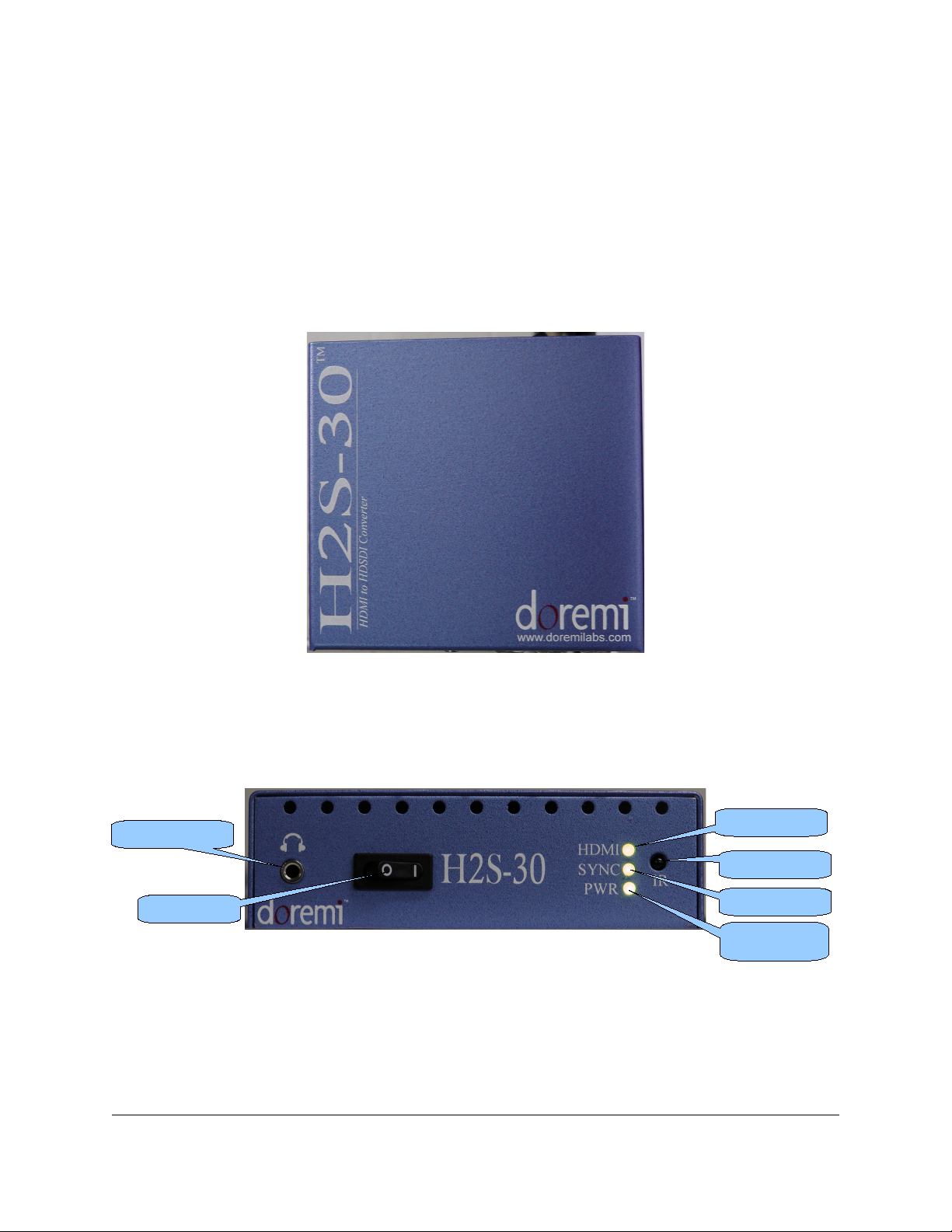
2.1.1 H2S-30 Top View....................................................................................................... 9
2.1.2 H2S-30 Front Panel....................................................................................................9
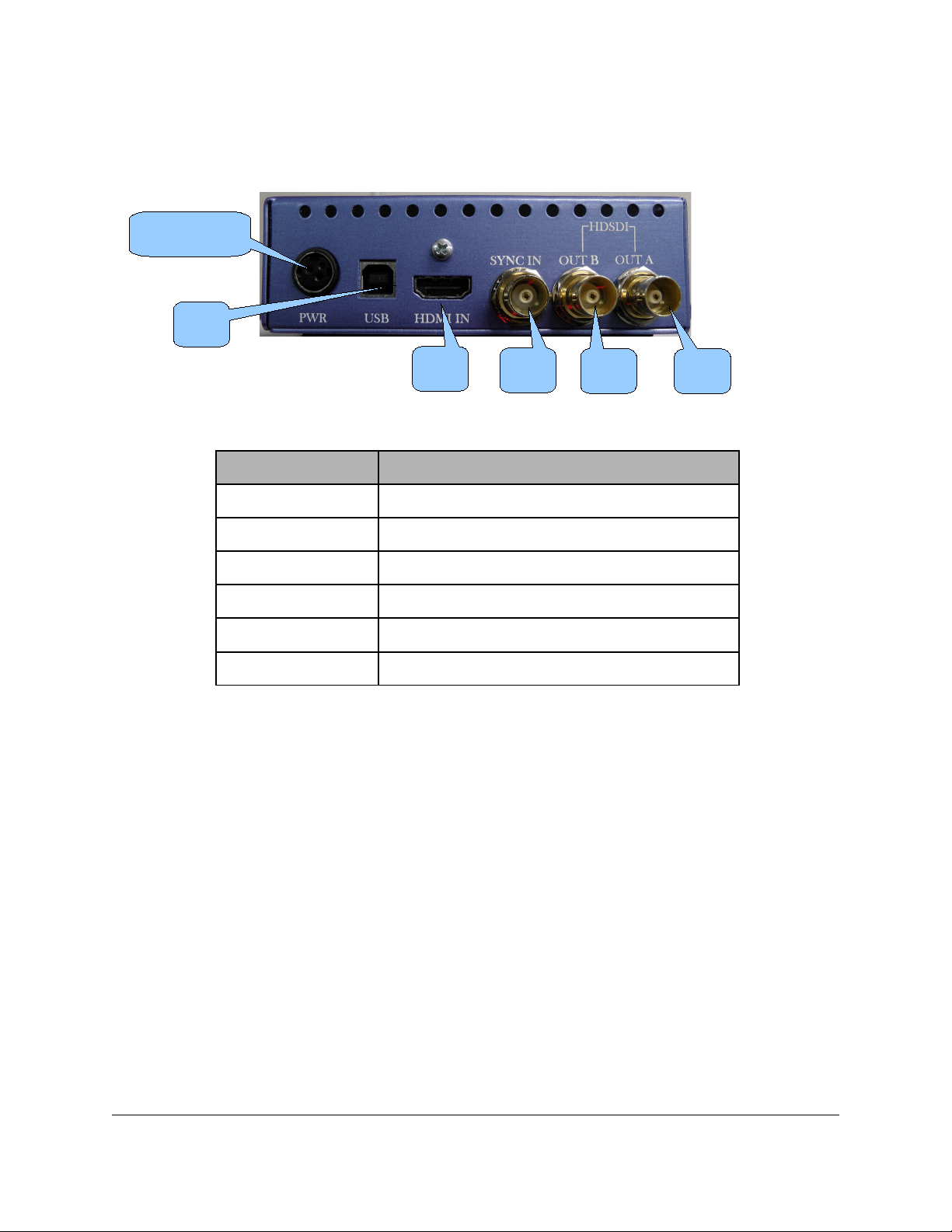
2.1.3 H2S-30 Rear Panel..................................................................................................10
2.2 Supported Formats.......................................................................................................... 11
3 H2S OS Menu System Overview......................................................................................12
3.1 Input Menu......................................................................................................................12
3.2 Output Menu....................................................................................................................13
3.2.1 Color Space..............................................................................................................15
3.3 Image Menu....................................................................................................................15
3.4 Sync Menu......................................................................................................................17
3.5 Audio Menu.....................................................................................................................18
3.5.1 Supported Audio Sa ple Rates................................................................................18
3.6 On Screen isplay (OS ) Menu......................................................................................19
3.7 System Menu..................................................................................................................20
3.8 Status Menu....................................................................................................................20
4 Infrared Remote Controller.................................................................................................21
4.1 Remote Controller Overview............................................................................................21
4.2 Remote Controller Functions...........................................................................................22
4.3 Input Source Setting........................................................................................................23
4.3.1 SDI Output For at...................................................................................................23
4.3.2 Setting the IR Channel..............................................................................................24
5 oremi Universal Interface Software ( UIS)......................................................................25
5.1 UIS Installation..............................................................................................................25
5.2 oremi Universal Interface Software Overview...............................................................28
5.3 Settings Field...................................................................................................................29
5.4 Tabs escription.............................................................................................................31
5.4.1 Input Tab..................................................................................................................31
5.4.2 Output Tab...............................................................................................................31
5.4.3 I age Tab................................................................................................................32
5.4.4 Sync I/O Tab.............................................................................................................34
5.4.5 Audio Tab.................................................................................................................35
5.4.6 OSD Tab..................................................................................................................36
5.4.7 Syste Tab..............................................................................................................37
6 Firmware Update..................................................................................................................39
6.1 USB Update....................................................................................................................39
7 Acronyms............................................................................................................................. 40
8 ocument Revision History................................................................................................41
H2S.OM.001539. RM Page 2 Version 1.3
oremi Labs

Software License Agreement
The software license agreement can be found at the following location:
http://www.doremilabs.com/support/proav-support/proav-warranties/
Hardware Warranty
The hardware warranty can be found at the following location:
http://www.doremilabs.com/support/proav-support/proav-warranties/
H MI
The terms H MI and H MI High- efinition Multimedia Interface, and the H MI Logo are
trademarks or registered trademarks of H MI Licensing LLC in the United States and other
countries.
H2S.OM.001539. RM Page 3 Version 1.3
oremi Labs

WARNING
THIS EVICE MUST BE GROUN E
IMPORTANT
Power requirements for electrical equipment vary from area to area. Please ensure that the
H2S-30 meets the power requirements in the surrounding area. If in doubt, consult a qualified
electrician or a oremi Labs dealer.
H2S-30 Power Ratings
•The H2S-30 should only be used with a oremi approved power supply.
•Power Supply Specifications:
•AC Input: 100-240V~, 1.2A, 50-60Hz
•Output 12V C, 3.0A (36W Max.)
•H2S-30 Power Requirements
•12V C, .12A
H2S.OM.001539. RM Page 4 Version 1.3
oremi Labs

Protecting Yourself and the H2S-30
Never touch the AC plug with wet hands. Always disconnect the H2S-30 from the power supply
by pulling on the plug, not the cord. Allow only a oremi Labs dealer or qualified professional
engineer to repair or re-assemble the H2S-30. Apart from voiding the warranty, unauthorized
engineers might touch live internal parts and receive a serious electric shock. o not put, or
allow anyone to put any object, especially metal objects, into the H2S-30. Use only oremi
approved power supply.
If water or any other liquid is spilled into or onto the H2S-30, disconnect the power and call a
oremi dealer. The unit must be well ventilated and away from direct sunlight. To avoid damage
to internal circuitry, as well as the external finish, keep the H2S-30 away from direct sources of
heat (heater vents, stoves, radiators). Avoid using flammable aerosols near the H2S-30. They
can damage the surface area and may ignite. o not use denatured alcohol, paint thinner, or
similar chemicals to clean the H2S-30. This can damage the unit.
Modification of this equipment is dangerous and can result in the functions of the H2S-30 being
impaired. Never attempt to modify the equipment in any way. In order to ensure optimum
performance of the H2S-30, select the setup location carefully and make sure the equipment is
used properly. Avoid setting up the H2S-30 in the following locations:
•In a humid or dusty environment.
•In a room with poor ventilation.
•On a surface which is not level.
•Inside a moving vehicle where it will be subject to vibration.
•In an extremely hot or cold environment.
H2S.OM.001539. RM Page 5 Version 1.3
oremi Labs

C A U T I O N
R I S K O F E L E C T R I C S H O C K
D O N O T O P E N
!
C A U T I O N : T O R E D U C E T H E R I S K O F E L E C T R I C S H O C K ,
D O N O T R E M O V E C O V E R ( O R B A C K ) .
N O U S E R - S E R V I C E A B L E P A R T S I N S I D E .
R E F E R S E R V I C I N G T O Q U A L I F I E D S E R V I C E P E R S O N N E L .
T h e l i g h t n i n g f l a s h w i t h t h e a r r o w h e a d s y m b o l s u p e r i m p o s e d
a c r o s s a g r a p h i c a l r e p r e s e n t a t i o n o f a p e r s o n , w i t h i n a n e q u i l a t e r a l
t r i a n g l e , i s i n t e n d e d t o a l e r t t h e u s e r t o t h e p r e s e n c e o f u n i n s u l a t e d
“ d a n g e r o u s v o l t a g e ” w i t h i n t h e p r o d u c t ’ s e n c l o s u r e ; t h a t m a y b e
o f s u f f i c i e n t m a g n i t u d e t o c o n s t i t u t e a r i s k o f e l e c t r i c s h o c k .
!
T h e e x c l a m a t i o n p o i n t w i t h i n a n e q u i l a t e r a l t r i a n g l e i s i n t e n d e d t o
a l e r t t h e u s e r t o t h e p r e s e n c e o f i m p o r t a n t o p e r a t i n g a n d
m a i n t e n a n c e ( s e r v i c i n g ) i n s t r u c t i o n s i n t h e l i t e r a t u r e
a c c o m p a n y i n g t h e a p p l i a n c e .
W A R N I N G ! !
T o p r e v e n t f i r e o r s h o c k h a z a r d , d o n o t e x p o s e t h i s a p p l i a n c e t o r a i n o r m o i s t u r e
H2S.OM.001539. RM Page 6 Version 1.3
oremi Labs

CE NOTICE
Marking by the symbol indicates compliance of the device to the EMC (Electromagnetic
Compatibility) directive and to the Low Voltage directive of the European Community. The
marking is indicative that the device meets or exceeds the following technical standards:
•EN 55022 "Limits and Methods of Measurement of Radio Interface Characteristics of
Information Technology Equipment".
•A " eclaration of Conformity" in accordance with the above standard has been made
and is on file at oremi.
H2S.OM.001539. RM Page 7 Version 1.3
oremi Labs

1 Introduction
1.1 Purpose
This document provides guidance on how to use the H2S-30 H MI® to S I converter that
incorporates High- efinition Multimedia Interface technology, as well as the oremi Universal
Interface Software ( UIS). It explains all features of the H2S as well as the infrared remote
control and how to upgrade the firmware.
1.2 Software Version
•UIS software version 4.2.3
•H2S-30 Firmware version 1.6.0
1.3 Contact Information
If in need of help or assistance, please contact oremi Labs Technical Services at
+ 1-818-562-1101 or email at [email protected] .
H2S.OM.001539. RM Page 8 Version 1.3
oremi Labs

2 H2S-30 Overview
2.1 H2S-30 escription
The H2S-30 is an H MI to S I format converter featuring H MI and S I connectors that
allow for any H MI input to be converted to any supported S I output format or scan rate. It
supports both S and H video and employs 12 bit bi-cubic interpolation to ensure the highest
quality picture. It also supports 3G S I and can tackle many conversion tasks.
2.1.1 H2S-30 Top View
Figure 1: H2S-30 Top View
2.1.2 H2S-30 Front Panel
The H2S-30 front panel is illustrated below:
Figure 2: H2S-30 Front Panel View
H2S.OM.001539. RM Page 9 Version 1.3
oremi Labs
Infrared Sensor
Headphone Jack
Power LE
SYNC LE
H MI LE
Power Switch

2.1.3 H2S-30 Rear Panel
The H2S-30 rear panel is illustrated below:
Figure 3: H2S-30 Rear Panel View
The rear panel has the following connectors:
Connector escription
USB USB connector
H MI in H MI input connector
S I-A out S I output connector – Link A
S I-B out S I output connector – Link B
SYNC in Sync input connector
Power Power supply connector
H2S.OM.001539. RM Page 10 Version 1.3
oremi Labs
USB
Power Connector
H MI
in
SYNC
in
S I-A
out
S I-B
out

2.2 Supported Formats
The table below summarizes all supported inputs and outputs available on the H2S-30.
Supported Input(s) Supported Output(s)
H MI: Supported input formats are
listed below:
640x480 = VGA
720x480i = 480i
720x480p = 480p
1440x480i = 480i
720x576i = 576i
720x576p = 576p
1440x576i = 576i
800x600 = SVGA
1280x720 = 720p
1024x768 = XGA
1280x768 = WXGA
1364x768 = WXGA
1366x768 = WXGA
1536x768 = 1536x768
1152x864 = XGA+
1280x960 = SXGA-
1280x1024 = SXGA
1364x1024 = 1364x1024
1400x1050 = SXGA+
1680x1050 = WSXGA+
1920x1080i = 1080i
1920x1080p = 1080p
2048x1080 = 2Kp
1600x1200 = UXGA
1920x1200 = WUXGA
S -S I: NTSC, PAL (SMPTE 259M-C
4:3 or 16:9, SMPTE 259M-C 4:3 or 16:9)
H -S I: all H formats (SMPTE 274,
SMPTE296, SMPTE372, SMPTE 424M
3G S I).
Note: 3G S I supported features include:
1080p at fps ≥ 47.95.
H2S.OM.001539. RM Page 11 Version 1.3
oremi Labs

3 H2S OS Menu System Overview
The H2S-30 is configured using the IR remote control to access the menu system through the
OS (see Section 4). Or by using the oremi Universal Interface Software ( UIS) - see Section
5.
3.1 Input Menu
The Input menu can be used to set up the input parameters.
Sub-Menu Value escription
Interface H MI/ VI
Pattern
Input interface setting.
Pattern produces 100% color
bar patterns with 8 channels of
audio. The odd channels being
at 1kHz and the even channels
at 2kHz.
H MI/ VI color Auto
RGB
RGB ext
YCbCr 601
YCbCr 601 ext
YCbCr 709
YCbCr 709 ext
H MI/ VI input color setting.
Auto: Usually RGB.
Ext: designates extended color
range (full bandwidth) as
opposed to limiting the color
spectrum to comply with ITU
standards.
efault E I 720p 50
720p 60
1080i 25
1080i 30
1080p 50
1080p 60
WUXGA 50
WUXGA 60
efault E I setting.
When you feed a signal to the
H MI input, the H2S-30 has to
report a native resolution over
E I . This menu allows the
user to change the default
resolution of the H2S-30
between the available formats.
CAUTION: isconnect the
H MI/ VI source before
changing this setting.
H2S.OM.001539. RM Page 12 Version 1.3
oremi Labs

3.2 Output Menu
The Output menu can be used to set up the output parameters. See table below for more
information.
Sub-Menu Value escription
Interface S I The output interface is set to
S I by default. It is the only
output interface available.
S I Color Auto
RGB
RGB ext
YCbCr 601
YCbCr 601 ext
YCbCr 709
YCbCr 709 ext
XYZ’
Set the S I output color mode
Auto: 601 (S ) 709 (H ), RGB
(2K)
Ext: designates extended color
range (full bandwidth) as
opposed to limiting the color
spectrum to comply with ITU
standards.
Note: XYZ Colorspace is non-
linear.
S I Resolution NTSC
PAL
720p
1080i/sf
1080p
2Kp
2Kp Flat
Match Input
Set the S I output pixel
resolution.
Match Input: In this mode, the
S I output will have the same
resolution as the input source.
H2S.OM.001539. RM Page 13 Version 1.3
oremi Labs

Sub-Menu Value escription
S I Frequency 23.98
24
25
29.97
30
47.95
48
50
59.94
60
Match Input
Match Input x2
Set the S I output frame rate.
Match Input: In this mode, the
unit will set the S I output
resolution to match the input
resolution – or to the closest
output resolution if the exact
input resolution is not available.
Match Input x2: Match input x2
will output twice the input frame
rate.
e.g. Input= 1080p 30; Output=
1080p 60
S I Force Interl Off
On
Force the S I output to
interlaced (or Segmented
Frame)
Ancillary out Off
Bypass S I
Set the Ancillary data on the
S I output.
- Off: No VANC on S I output.
- Bypass S I: Pass Ancillary
data from H MI input to S I
output.
Time Code Off
Bypass S I
Free wheel
Set the embedded (S I output)
Time code mode.
Off: No embedded timecode on
S I output.
Bypass S I: Pass embedded
timecode from H MI input to
S I output.
Free wheel: Generate
embedded Time Code starting
at the moment this option is
enabled.
H2S.OM.001539. RM Page 14 Version 1.3
oremi Labs

3.2.1 Color Space
The ITU-R BT.709-5 (H formats) and ITU-R BT.601-5 (S formats) standards define the range
of color values in a digital signal to be:
•16 to 240 for 8bit coding
•64 to 960 for 10bit coding
The H2S-30 color space conversion supports these standards, but it also supports full range by
allowing the color values to be between:
•0 to 255 for 8bit coding
•0 to 1023 for 10bit coding
On the H2S-30, the full range modes are designated by the “ext” following the color space
conversion mode.
3.3 Image Menu
The Image menu can be used to set up the image parameters.
Sub-Menu Value escription
Brightness 0% to 100% Brightness value setting
Contrast 0% to 100% Contrast value setting
Scaling Aspect Ratio
Fill
Aspect Fit H
Aspect Fit V
One to One
Scaling value setting
Aspect Ratio: Maintain input
aspect ratio.
Fill: Scale to fill the output
resolution.
Aspect Fit H (V): Scale
Horizontally (Vertically) to fill the
output resolution.
One to One: No Scaling.
e-interlacing Off
On
Motion
Set the e-interlacing mode.
Motion: e-interlacing is based
on motion.
S Ratio 4:3 igital
16:9 igital
4:3 Analog
16:9 Analog
efine the source PAR for S
formats.
For source PAR of 8:9 or 16:15
use 4:3 igital or 16:9 igital.
For source PAR of 10:11 or
59:54 use 4:3 Analog or 16:9
Analog.
H2S.OM.001539. RM Page 15 Version 1.3
oremi Labs

Sub-Menu Value escription
Input LUT User efined
0.1 to 4.0
Set the input Gamma
correction.
For User efined Input LUT use
the UIS software (see Section
5.4.3)
Output LUT User efined
0.1 to 4.0
Set the output Gamma
correction.
For User efined Output LUT
use the UIS software (see
Section 5.4.3)
H2S.OM.001539. RM Page 16 Version 1.3
oremi Labs

3.4 Sync Menu
The Sync menu can be used to set up the sync parameters.
Sub-Menu Value escription
Input H MI/ VI
Extern
Extern: Sync is derived from
the Sync Input connector.
H offset X pixels Horizontal Sync offset in pixels
V offset X lines Vertical Sync offset in lines
H2S.OM.001539. RM Page 17 Version 1.3
oremi Labs

3.5 Audio Menu
The Audio menu can be used to set up the audio parameters.
Sub-Menu Value escription
Input VI/H MI Audio input is set to VI/H MI
by default. It is the only input
interface available.
elay X frames Audio delay setting from -1 to
+2 frames.
Level -18, -12, -6, 0, +6, +12,
+18 dB
Audio Output level setting.
Swap Channels 3
and 4
Off
On
When selected input channel 3
will be output on channel 4 and
input channel 4 will be output
on channel 3.
S I Out Groups Auto
1
1+2
1+2+3
1+2+3+4
Off
Set the embedded S I active
audio groups.
Auto: All audio inputs will be
present on the S I output.
Each group has 4 audio
channels, when 1+2+3+4 is
selected, all 16 audio channels
will be present.
Off: No embedded audio on S I
output.
3.5.1 Supported Audio Sample Rates
•H MI Input: 48 kHz
•S I Output: 48 kHz
Note: The H2S-30 does not support audio sample rate conversions. If using the Embedded S I
Audio output, you must use 48 kHz audio on the H MI input. Using unsupported audio sample
rates will result in degraded audio output.
H2S.OM.001539. RM Page 18 Version 1.3
oremi Labs

3.6 On Screen isplay (OS ) Menu
The OS menu can be used to set up the OS parameters.
Sub-Menu Value escription
OS Enable Yes
No
Enable or disable On Screen
isplay.
OS timeout X s (seconds) On Screen isplay timeout in
seconds. Set to Infinite to keep
it always on.
OS H Position Horizontal Position Bar OS horizontal position
OS V position Vertical Position Bar OS vertical position
OS Status
The OS Status
will show the burn-
in window
timecode, I/O
status and audio
levels when the
OS is not active.
Off
TC BIW
Input Status
Output Status
Burn In Window and Status
display
Off: BIW and Status not
displayed
TC BIW: Timecode is shown in
a burn-in window on the H2S-
30 output
Input Status: In addition to the
timecode BIW, the H2S-30
output will display the Input
Status including Audio levels,
Closed Caption presence, Input
Format and CRC errors
(flashing red dot).
Output Status: In addition to the
timecode BIW, the H2S-30
output will display the Output
Status.
TC Color White/Black
W/B Zoom
Black/White
B/W Zoom
Burn In Window type setting.
H2S.OM.001539. RM Page 19 Version 1.3
oremi Labs

3.7 System Menu
The System menu allows access to the system parameters.
Sub-Menu escription
Save Save current settings to flash.
Select to Save, when the “?” appears select again
to confirm
Firmware: x.y Firmware version
Serial: zzzzzzz Serial number
License: uuuuuuuu License number
Temp: vv C Temperature (in degree Celsius)
Standby Standby mode: Puts the unit in Power own
mode
Auto Standby Auto Standby mode: Sets the idle time duration
before the unit goes in power down mode
automatically
IR Infra-Red. To avoid IR interference with multiple
H2S-30 units, assign each a different IR code
from 0x0 to 0xF (16 total) default is 0. Set the IP
switch on the oremi IR remote accordingly
The IR channel can also be set to OFF, which
disables the IR remote control completely
3.8 Status Menu
The Status menu can be used to view the Input and Output status.
Sub-Menu escription
In:
Out:
Input and Output format status information
H2S.OM.001539. RM Page 20 Version 1.3
oremi Labs
Table of contents
Other Doremi Media Converter manuals