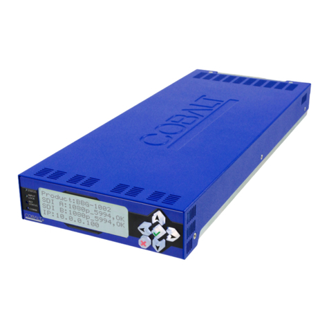
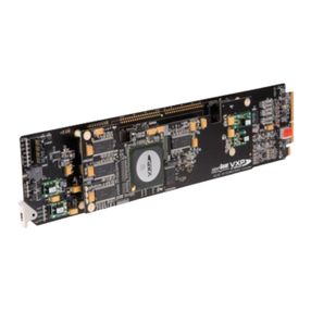
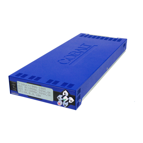
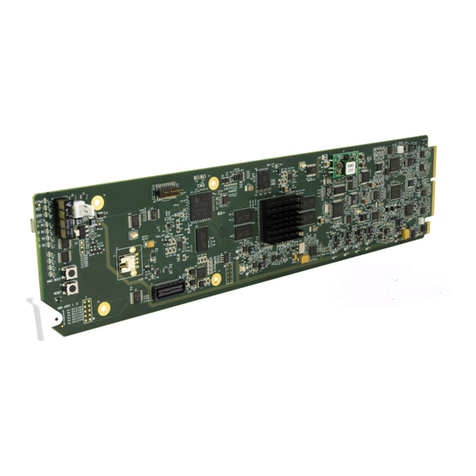
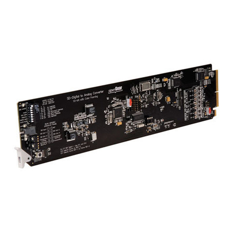
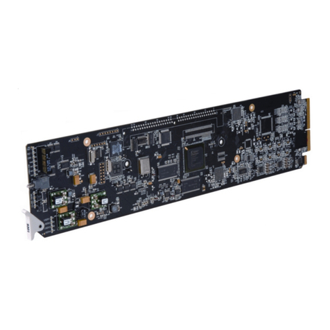
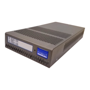
The COBALT 6540 is a high quality 10-bit digital to analog encoder for converting 525/625 4:2:2
SDI signals to analog composite, Y/C and component (YPbPr or RGB). The 6540 auto-detects
the line-input standard and outputs the corresponding NTSC or PAL standard. The user can
configure the default PAL outputs to be PAL-B/D/G/H/I, PAL N or PAL 60 and NSTC M or N.
Pedestal selection can be enabled or disabled for NTSC operation.
The 6540 can be externally configured for three different analog output configurations: all
composite, dual composite with Y/C, composite with component or dual Y/C. The 6540 supports
four different component output modes: BetaCam™, MII™, SMPTE/N10 and RGB. The
encoding process is 10-bit with sample conversion from 4:2:2 to 4:4:4, to 8:8:8 (2x-output mode)
or 16:16:16 (4x output mode). Full user digital processing (proc.) controls are available to the end
user for adjusting black level, Y gain, saturation and hue. Advanced controls include VBI
blanking, line by line VBI pedestal control, extended filtering, DNR and Gamma configuration.
All adjustments can be saved to non-volatile memory or factory defaults can be restored. A de-
jitter VCXO is included to reduce input jitter from high frequencies down to 2Hz.
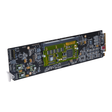
The 6540 includes two reclocked digital output copies or one when the optional color framing
board is installed. One digital output BNC is re-purposed for black burst input. The user must
adjust the SDI source’s H-phase for position alignment. SCH phase is user adjustable on the
6540.
Figure 1 - 6540 BlockDiagram
Figure 2 - External Configuration Settings.
SWITCH-1 SETTINGS
S 1-3 VIDEO INPUT AND COLOR ENCODING MODE (See figure 2.)
S 4 COLOR
OFF - B&W output ON - Color enabled
S 5 COLOR BARS ON/OFF
OFF - Display video ON - Display color bars
S 6 SETUP (NTSC modes only – PAL pedestal is always off)
OFF - No pedestal ON - 7.5 IRE pedestal added
S 7 OUTPUT SAMPLE MODE (interior switch)
OFF - 2x (8:8:8) ON - 4x (16:16:16)
S 8 DE-JITTER FILTER (interior switch)
OFF - De-jitter filter off ON - De-jitter filter on
DUAL Y/C MODE
Dual Y/C mode is an extended feature of the 6540. To enable, remove the top cover and set
Jumper J21 to the two pins nearest J8 and set the external switches 1,2&3 to ON, OFF, OFF.
REFERENCE CONFIGURATION AND TERMINATION (Color Framing Option)
Remove top cover and locate SW-1 (BNC function select) and SW-2 (Ref 75 termination). Set
SW-1 away from the power-input connector to enable reference input or toward the power input
connector to enable the second SDI output. Set SW-2 away from the reference input BNC for 75-
ohm termination or toward the reference input BNC for no Reference termination.
LED INDICATOR
The front panel LED indicates video lock when On and loss of video when blinking. A dark LED
indicates loss of power. Internal switches S2&3 need to be set to 0-0 for normal LED operation.
DIGITAL PROC. GAIN ADJUSTMENTS
Full control of Y-gain, Y-black level, color saturation and hue can be User controlled via S3, 2, 4
& 5. YPbPr and RGB have no hue control. To restore factory defaults, set S3,2 to 8-8 and press
either S4 or S5. To set Proc. values configure S3,2 as shown below and press S4 & 5 to adjust
levels. To save settings dial S3,2 to 9-9 and press either S4 or S5. To restore factory defaults dial
S3,2 to 8-8 and press either S4 or S5.
Switch S3,S2 Functions (remove bottom cover)
1-1 Y-gain
1-2 Y-black level
1-3 Color saturation
1-4 Hue +/-22.5º in 0.18º increments
1-5 SCH phase
1-6 1-6 Sharpness –4dB to +4dB in 12 steps
2-7 VBI lines 10-20 encoded LED On = encoded, Off = VBI blanked
5-0 VBI Pedestal odd lines 10-18 (NTSC only)
5-1 VBI Pedestal odd lines 19-25
5-2 VBI Pedestal even lines 10-18
5-3 VBI Pedestal even lines 19-25
5-4 Global VBI pedestal LED on = VBI Pedestal added Off = pedestal removed
Note 5-4 over-writes settings of 5-0 through 5.3
ANALOG OUTPUT CALIBRATION
Turn on bars and composite mode, restore Digital Proc. Factory Defaults S3,2 set to 8-8 and press
up or down switch once. Connect output to calibrated waveform monitor. Place 6540 into all
composite mode and adjust R144 for 100 IRE at J7, then adjust the three remaining pots R132 for
J5, R153 for J3, R242 for J1 so that you have 100IRE of video at each output. Place 6540 into
BetaCam mode and adjust R234 for 100 IRE at J1, adjust R142, R121 for 75% vectors on J3, J5.
Config & Proc SW
Microprocessor
De-jitter 10 bit Encoding, Dig. Proc., Gamma Cntl.,
DNR, Filtering, 8:8:8 or 16:16:16 Output
Filter, Mux
Output Amps
SDI Input
Processing
SDI DA
SW Ref CF
SDI Input
SDI Output
SDI Output or
Ref Input
Analog Outputs Config. as:
4 Composite
2 Composite & Y/C
2 Y/C
1 Composite & Component
6540 User Configuration Settings
1 2 3 4 5 6 7 8 Function
0n 0n 0n All Composite
0n 0ff 0n Y/C, Composite
0ff 0n 0n YPbPr BetaCamTM, Composite
0ff 0n 0ff YPbPr MIITM, Composite
0ff 0ff 0n YPbPr SMPTE, Composite
0ff 0ff 0ff RGB, Composite
SW4 Color 0n = Color On 0ff = Color Off
SW5 Test Bars 0n = Bars Output 0ff = Input Video Output
SW6 Pedestal 0n = Add Ped 0ff = Bypass
SW7 Sample Mode 0n = 4X Over-Sampled 0ff = 2X Over-Sampled
SW8 Clock Filter 0n = Filtered 0ff = No-Filter
Examples:
1 2 3 4 5 6 7 8 Function
0n 0n 0n 0n 0ff 0n 0n 0n All Composite
0ff 0n 0n 0n 0ff 0n 0n 0n Component BetaCamTM
0ff 0ff 0n 0n 0ff 0ff 0n 0n Component SMPTE
0n 0ff 0n 0n 0ff 0n 0n 0n Y/C
1
2
3
4
5
6
OFF ON
