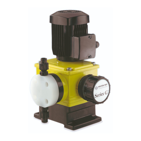
Dosapro Milton Roy G Series User manual

INSTRUCTION MANUAL
FOR INSTALLATION,
OPERATING,
AND MAINTENANCE.
Pump
SERIES G™ MODEL B
This manual should be made available to the person responsible for installation,
operating and maintenance.
Date : 12/98 O / Ref : 160.0704.001. Rev. A
Replaces Rev. A, 04/97


G, B, L001, Rév. A, 1298
CONTENTS
HOW TO USE THIS MANUAL ?
I - DESCRIPTION
I - 1. Unpacking and storage
I - 2. Description
I - 3. Operating principle of the pump
I - 4. Safety and health instructions
II - INSTALLATION
II - 1. Hydraulic installation
II - 2. Drip collection
II - 3. Handling
II - 4. Setting up
II - 5. Electrical installation
III - START UP
III - 1. Procedures before start up
III - 2. Start up
III - 3. Failures on start up
III - 4. Operation - Schedule of checks and maintenance operations
IV - ROUTINE MAINTENANCE
IV - 1. Occurrence of a leak from detection port
IV - 2. Oil change
IV - 3. Checking the pump capacity
IV - 4. Tracing causes of failure
IV - 5. Ordering spare parts
V - PREVENTIVE MAINTENANCE - ANNUAL OVERHAUL
V - 1. Spare parts required for annual overhaul
V - 2. Sequential actions

G, B, L001, Rév. A, 1298
VI - SERVICING THE LIQUID END AND THE LIQUID END MOUNTING ASSEMBLY
VI - 1. General
VI - 2. Removing the liquid end and the liquid end mounting assembly
VI - 3. Reinstalling the liquid end and the liquid end mounting assembly
TECHNICAL CHARACTERISTICS
«EC » DECLARATION OF CONFORMITY
GUARANTEE
LIST OF « TECHNICAL ASSISTANCE » AND « SPARE PARTS » DEPARTMENTS

G, B, L001, Rév. A
HOW TO USE THIS MANUAL ?
IMPORTANT: You should read the following paragraphs carefully in order to understand
how to use this manual efficiently.
This manual corresponds to the type of pumps mentioned on the cover page.
There may be several different construction versions for each type of pump, however, and
this manual takes those differences into account.
The paragraphs or lines specific to a given construction are:
•indented compared to the main text body,
•marked by a vertical line indicating the specific text,
•marked by a rectangle specifying the corresponding code.
Note: When first reading this document, you are advised to highlight the « boxes »
corresponding to the construction of your equipment so the manual will be easier to read in
future.
MARKING USED IN THE MANUAL
You will find, below, the list of the various possibilities and the corresponding markings.
In addition, to identify the type of construction of your pump, the table includes the pump
code shown on the identification plate attached to the pump (Fig. 4.5a). Caution : only
characters mentioned are to be taken into account when reading this manual.
Examples of pump code : G 5 3 9 - 5 4 1 Q
G 6 8 9 - 5 6 7 N
Your pump code : G - 5
(to be filled in)
Use the following table to identify the markings of our pump.
Mark Description Pump code
1Liquid end, PP or mixed
Liquid end, PVC G-1
8***
2Liquid end, PVDF G-2
7Liquid end, stainless steel (54..) G-4 7
7B Liquid end, stainless steel (56..) G-6 7
HHigh-viscosity version G-1H
Tri 3-phase power supply G9 or J -
Mono Single-phase power supply G0 or C -
*** Character has to be different from « H ».

I - 1
G, B, L001, Rév. A, 1298
PART I - DESCRIPTION
I - 1. UNPACKING AND STORAGE
UNPACKING
The packaging must be carefully examined on receipt in order to ensure that the contents
have not sustained any obvious damage. Precautions must be taken when opening the
packaging in order to avoid damaging accessories which may be secured inside the
packaging. Examine the contents and check them off against the delivery note.
STORAGE PRECAUTIONS
Storage for less than six months
Equipment shall preferably be stored in its original packaging and protected from adverse
weather conditions.
Storage for more than six months
•Store the pump in its original packaging. In addition, packaging in heat-sealing plastic
cover and dessicant bags must be provided for. The quantity of dessicant bags should
be adapted to the storage period and to the packaging volume.
•Store protected from adverse weather conditions.
I - 2. DESCRIPTION
The « SERIES G » Model B pump is a compact electromechanical metering pump that is oil
lubricated with a sealed housing, with capacity adjustment in operation or when stopped.
It is made up of the following components (Fig. 1.2a):
•a drive device comprising a motor [1],
•a mechanical assembly [2],
•a liquid end [3].
Leak-tightness between the mechanical assembly and the liquid end is ensured by means
of a bellows.
Capacity adjustment is controlled either manually (by a stroke adjustment knob [4]) or
automatically (such as by a servomotor).
Various components of the pump are shown in Figure 1.2a.
Note: For further information on the automatic control system, see the relevant specific
manual.

I - 2
G, B, L001, Rév. A, 1298
1Motor 9Leak detection port
2Mechanical assembly 11 Valve assembly (suction)
3Liquid end 12 Valve assembly (discharge)
4Stroke adjustment knob 25 Filler plug
6Liquid end mounting assembly 26 Drain plug
8Stroke locking device
Fig. 1.2a: Model B, series G pump

I - 3
G, B, L001, Rév. A, 1298
I - 3. OPERATING PRINCIPLE OF THE PUMP
See Figures 1.3b and 1.3c.
Fig. 1.3b : Setting to zero stroke
Suction phase Discharge phase
Fig. 1.3c : Setting to maximum stroke
1Worm 7Diaphragm
2Tangential wheel 10 Stroke = two times the distance between (A) and (B)
3Eccentric 11 Position at rear neutral point
4Connecting rod 12 Position at forward neutral point
6Crosshead
MECHANICAL ASSEMBLY
The mechanical assembly works on the principle of a variable eccentric.
The rotational motion of the motor is transmitted by the worm [1] to the tangential gear [2]
which is linked to an eccentric system [3].

I - 4
G, B, L001, Rév. A, 1298
The connecting rod [4], attached to this eccentric system, converts the rotary motion into a
reciprocating linear motion with variable stroke. The stroke depends upon the eccentricity
between the axis of rotation of the tangential wheel [A] and an axis of the connecting rod
[B]. The stroke is adjusted by moving the crosshead [6] by means of a stroke adjustment
screw. The movement of the crosshead causes movement of the male eccentric piece
which modifies the position of the connecting rod axis.
When the connecting rod axis [B] is aligned with the axis of the tangential wheel [A], the
connecting rod does not move and the stroke is zero.
Figure 1.3b shows the functional diagram at zero stroke.
Figure 1.3c shows the functional diagram at maximum stroke.
MECHANICALLY CONTROLLED DIAPHRAGM-TYPE LIQUID END
The diaphragm [7] is mechanically linked to the connecting rod [4] and has the same
reciprocating motion.
During the suction phase, the movement of the diaphragm allows the suction of a given
volume of fluid.
In the discharge phase, the process is reversed. The diaphragm then expels the fluid.
1 - 4. SAFETY AND HEALTH INSTRUCTIONS
The personnel responsible for installing, operating and maintaining this equipment must
become acquainted with, assimilate and comply with the contents of this manual in order to:
•avoid any possible risk to themselves or to third parties,
•ensure the reliability of the equipment,
•avoid any error or pollution due to incorrect operation.
Any servicing on this equipment must be carried out when it is stopped. Any accidental
start-up must be prevented (either by locking the switch or removing the fuse on the power
supply line).
A notice must be attached to the location of the switch to warn that servicing is being
carried out on the equipment.
During oil changing operations, the waste oil must be collected in a suitable receptacle. Any
overflow of oil which may result must be removed using a degreasing agent suitable for the
operating conditions.
Soiled cleaning cloths must be stored in suitable receptacles. The oil, degreasing agent and
cleaning cloths must be stored in accordance with the rules on pollution.
Switch off the power supply as soon as any fault is detected during operation: abnormal
heating or unusual noise.
Special care has to be taken for chemicals used in the process (acids, bases,
oxiding/reducing solutions, ...).

II - 1
G, B, L001, Rév. A
PART II - INSTALLATION
II - 1. HYDRAULIC INSTALLATION
All the information concerning the hydraulic installation of a metering pump is detailed in a
volume, « Generalities about metering pumps installation ». You should consult that manual
to determine the installation required for your application.
Certain essential points are, however, also briefly covered in this document.
GENERAL
•Piping layout
There must be no swan-necks or stagnant volumes which are liable to trap air or gas.
Stresses due to incorrect alignment of piping with respect to the centreline of valves must
be avoided as far as possible.
•Remove burrs and clean the piping before fitting.
•It is advisable to provide for a calibrating chamber in order to calibrate the pump in
service conditions.
PIPING ON THE SUCTION CIRCUIT
•If your pump is flooded, a shutt-off valve will be required
•Check whether the diameter and length of pipe are compatible with the pump's maximum
capacity.
•Install the pump as near as possible to the suction tank.
•If the length of the suction pipe exceeds 3 m, increase the piping cross-section.
•It is highly recommended to install a pulsation dampener.
PIPING ON THE DISCHARGE CIRCUIT
•Provide for a safety valve on the discharge pipe, designed to protect the installation.
•Check whether it is necessary to install a pulsation dampener, according to the width and
diameter of the tubing.
•It is advisable to install a priming valve on the discharge circuit in order to make starting
and maintenance of the pump easier.
Typical installations are shown schematically in Figure 2.1a.

II - 2
G, B, L001, Rév. A
1Tank 8Injection nozzle
2Foot valve (equipped with a filter) 9Shutt-off valve
4Metering pump 10 Filter
6Utilization 11 Pulsation dampener
7Safety valve
Fig. 2.1a : Diagrams of typical installations

II - 3
G, B, L001, Rév. A
II - 2. DRIP COLLECTION
Provide for outlets so that any leak or drips can be easily drained off without any danger.
This is especially important in the case of harmful liquids.
See Figure 1.2a.
Position a tray under the plain hole (detection port [9]) located at the bottom of the liquid
end mounting assembly to collect leaks in the event of rupture of the diaphragm or boot.
II - 3. HANDLING
Choose lifting equipment that is compatible with the weight of the pump. (See TECHNICAL
CHARACTERISTICS at the end of the illustrations manual).
See Figure 2.3a.
Handling requires the following precautions :
Fit one sling under the motor and the liquid end.
Check that the assembly is correctly balanced before starting to move it.
Secure the pump as soon as it is positioned in its required location (see Chapter II - 4.
Setting up).
Fig. 2.3a : Handling
II - 4. SETTING UP
Secure the pump to a horizontal support (see attaching holes). Leave enough clear space
around the pump to be able to carry out servicing operations and adjustments.
Pumps installed outdoors must be protected by a shelter (according to the climatic
conditions).

II - 4
G, B, L001, Rév. A
II - 5. ELECTRICAL INSTALLATION
CONNECTING THE MOTOR
Check the specifications of the motor and compare them with the voltage available on your
installation before making connections. Connect up the motor in accordance with the
instructions in the terminal box (Fig. 2.5a).
A delta connection is required to connect up to a 230 V 3-phase power supply (Fig.
2.5b).
A star connection is required to connect up to a 400 V 3-phase power supply (Fig.
2.5c).
For connection in SINGLE-PHASE mode, see Figure 2.5d.
CAUTION : Do not forget to connect the earth terminal on the motor [PE] (Fig. 2.5a) to the
equipment earth conductor.
The electrical protection installed for the motor (fuse or thermal protection) must be suitable
for the motor's rated current.
Fig. 2.5a : Motor terminal box
Fig. 2.5b :
230 V delta connection Fig. 2.5c :
400 V star connection Fig. 2.5d :
Single-phase connection
Tri
Mono

III - 1
G, B, L001, Rév. 0
PART III - START UP
III - 1. PROCEDURES BEFORE START UP
Special care has to be taken for chemicals used in the process (acids, bases,
oxiding/reducing solutions, ...).
See Figure 1.2a.
•Check that the pump is secured to its support (Chapter II - 4. Setting up).
•Remove the plug [25] and fill the housing with the supplied oil (2,8 l approximetely).
Check oil level by mean of the gauge of the plug [25].
•Check the opening of all the isolating valves installed on the suction and discharge
circuits. If the discharge circuit is equipped with an injection nozzle or a back-pressure
valve, open the priming valve for discharge (if there is no priming valve, disconnect the
discharge pipe). This makes it possible to verify that there is liquid present if the pump is
installed in flooded suction, or to prime the pump if it is installed in suction lift.
•Set the pump capacity adjustment to 0% (stroke adjustment knob [4]).
Checking the electrical connection of the motor
Start up the pump to check the motor's direction of rotation. It must comply with that
indicated by the arrow marked on the pump housing.
To reverse the motor's direction of rotation, invert A and B or A and C (See Figure
2.5b or 2.5c). Stop the pump.
To reverse the motor's direction of rotation, see the instructions in the terminal box.
Stop the pump.
III - 2. START UP
•Once all the checks and procedures described in the previous section have been carried
out, start up the pump.
•Check visually and by listening. (In particular, check that there are no suspicious noises).
•Make sure that the stroke adjustment knob is unlocked. Adjust the pump capacity
gradually from 0 % to 100 % and control the liquid output at priming valve or discharge
check valve.
•As soon as the liquid to be pumped flows out of the priming valve or the discharge valve,
priming has been achieved. Close the priming valve or reconnect the discharge pipe, as
applicable.
•Set the pump to the desired capacity. Lock the stroke adjustment knob with the stroke
locking screw [8] (Fig. 1.2a).
Tri
Mono

III - 2
G, B, L001, Rév. 0
III - 3. FAILURES ON START UP
PROBLEMS WITH MOTOR
The motor runs with difficulty and heats up.
•The characteristics of the electrical power supply do not match the specifications of the
motor.
•One phase is incorrectly connected.
•The electrical connection used is not suitable.
The motor overheats.
•Check that the pressure on the discharge side is compatible with the equipment’s
capabilities.
•The direction of rotation of the motor is incorrect. (Check using the arrow
marked on the housing). Reverse the direction of rotation (see Chapter III - 1.
Procedures before start up, Checking the electrical connection of motor).
PROBLEMS WITH FLOW RATE
The flow rate is lower than desired
•The pump capacity is incorrectly adjusted: adjust the capacity to the desired value and
lock the stroke adjustment knob.
•The suction power is insufficient. (Piping cross-section too small or piping too long):
replace the pipes with ones with a larger cross-section or install the pump in flooded
suction.
•The leak-tightness of the suction pipes is unsatisfactory.
•The viscosity of the liquid is incompatible with the capabilities offered by your pump
version.
The capacity is greater than desired
•The pump capacity is incorrectly adjusted: adjust the capacity to the desired value and
lock the stroke adjustment knob.
•A syphoning phenomenon is observed: check that the suction pressure is not greater
than the discharge pressure. Install a 4FV or a back-pressure valve on the discharge
side.
•Too many flow pulsations : a pulsation dampener is required, or the pulsation dampener
installed is of the wrong size, or the pressurization of the pulsation dampener is incorrect.
The capacity is variable
•This problem may be due to particles from the piping which interfere with the operation of
the valve assemblies: clean the piping (if there is an abnormal presence of particles) and
the valve assemblies (see chapter IV - 2.).
Tri
Tri

III - 4
G, B, L001, Rév. 0
III - 4. OPERATION - SCHEDULE FOR CHECKS AND MAINTENANCE
OPERATIONS
The programme of checks and maintenance operations depends on the conditions in which
the equipment is used. For this reason, the following frequencies are given as an example
only. Individual users should adapt these frequencies to their own specific operating
conditions.
When Check Servicing See
Every month Check for the occurrence
of a leak from the
detection port
- if leak occurs -> Chapter IV -1
After 250 hours Change lubricating oil Chapter IV-2
Every 3 months Check by listening (no
knocking)
- if unsatisfactory -> Chapter IV-4
Every 6 months
(or 2,500 hours) Change lubricating oil Chapter IV-2
Frequency to be
defined according
to process
(approx. 1,000
hours)
Check on compliance of
flow rate Check on pump capacity Chapter IV-3
Every year (or
3,000 hours) Annual overhaul Part V
A model maintenance sheet is shown in Figure 3.4a to help you ensure follow-up of your
servicing actions (checking or maintenance).

III - 5
G, B, L001, Rév. 0
MAINTENANCE SHEET
Pump code : D.M.R. internal no. :
Liquid pumped :
Service Operation Date Hours Remarks
Fig. 3.4a : Model Maintenance Sheet

IV - 1
G, B, L001, Rév. 0
PART IV - ROUTINE MAINTENANCE
IV - 1. OCCURRENCE OF A LEAK FROM DETECTION PORT
Determine whether the product collected at the detection port [9] (Fig. 1.2a) is lubricating oil
or the pumped fluid.
•If the product is pumped fluid, the diaphragm is faulty. Proceed with its replacement
(see Part V).
•If the product is lubricating oil, the secondary diaphragm is faulty. Proceed with its
replacement (see Part V).
IV - 2. OIL CHANGE
LUBRICATING OIL
•Perform the first housing oil change after 250 hours' operation. Subsequent oil changes
will be carried out every 2,500 hours' operation or every six months.
•Disconnect the pump electrically, check that the equipment cannot be switched on
accidentally. Position a notice at the location of the switch.
Note
To avoid any risk of burning by the hot oil, protective gloves should be worn.
See Figure 1.2a.
•Unscrew the plug [26] and drain the oil into a tray. Put PTFE ribbon on the threads and
screw the plug.
•Remove the plug [25] and fill the housing with appropriate oil (2,8 l approximately).
Check compatibility of oil with conditions of use. Check oil level by mean of the gauge of
the plug [25].
•Quantity: see TECHNICAL CHARACTERISTICS at the end of the manual.
•Remove any overflow of oil immediately with a suitable degreasing agent for the
operating conditions.
Recommendations
•Standard conditions: standard oil
•Ambient temperature: > - 5°
•Max. oil temperature: + 90°

IV - 2
G, B, L001, Rév. 0
Table of equivalencies:
FUCHS RENEP 220
B.P. GR XP 220
CASTROL ALPHA SP 220
ELF REDUCTELF SP 220
FINA GIRAN 220
IGOL DYNAM SP 220
MOBIL OIL MOBILGEAR 630
SHELL OMALA 220
TOTAL CARTER EP 220
ESSO SPARTAN EP 220
•Special conditions : for example, low-temperature oil. Consult us.
IV - 3. CHECKING THE PUMP CAPACITY
This is a question of determining the curve representing the pump’s capacity according to
its setting.
Four measurements are sufficient (adjustment to 100 %,75 %, 50 % and 25 %).
Place the foot valve in a calibrating chamber (graduated reservoir). Measure the volume of
pumped liquid for a given period of time at the various settings.
Plot the curve and use it to determine the adjustment corresponding to the desired capacity.
IV - 4. TRACING CAUSES OF FAILURE
PROBLEMS WITH MOTOR
The motor does not run
The thermal relay has been tripped.
•The motor is defective.
•Wiring is defective.
•Check the parts of the mechanical assembly.
The motor heats up abnormally
•The quantity of lubricating oil is incorrect: trace the leak (see Chapter IV - 1.)
•The pump is used in conditions it was not designed for.

IV - 3
G, B, L001, Rév. 0
PROBLEMS WITH FLOW RATE
The pump produces no flow
•The pump capacity is adjusted to « 0 % » : Adjust the capacity to the desired value and
lock the stroke adjustment knob.
•The liquid end is unprimed: release the pressure on the discharge pipe and prime the
liquid end, or check the leak-tightness of the suction circuit.
•The balls of the valve assemblies are blocked by particles: clean or replace the valve
assemblies. First, check whether the presence of these particles is normal and take
corrective action if necessary.
•The diaphragm is faulty (rupture): see Chapter IV - 1. And replace the diaphragm (see
Part V).
The pump does not provide the required flow rate
•The pump capacity is incorrectly adjusted: adjust the capacity to the desired value and
lock the stroke adjustment knob.
•The ball seats and/or the balls are dirty or worn: clean or replace the ball seats and the
balls or the valve assemblies.
•The leak-tightness of the suction circuit is unsatisfactory: repair or replace the piping.
IV - 5. ORDERING SPARE PARTS
To make it easier to register your order for spare parts and ensure quicker delivery, please
provide us with the following details:
•information on the pump : type [1] and contract number [5]. These two items of
information are shown on the identification plate mounted on the pump (see Fig. 4.4a).
•Information on the spare part : reference, description and quantity. These items of
information are specified in the spare parts lists.
You will find the phone and fax number of the Spare Parts Department at the end of this
documentation.
Other manuals for G Series
1
This manual suits for next models
1
Table of contents
Other Dosapro Milton Roy Water Pump manuals
Popular Water Pump manuals by other brands

IWAKI PUMPS
IWAKI PUMPS EHN-YN instruction manual

BEKA
BEKA HPM-2S Original operating and assembly manual

Biral
Biral A 402 V2 Installation and operating instructions

CALEFFI
CALEFFI DeltaSol 268050 Installation and commissioning manual

Gardena
Gardena PTU 3000/4 Operator's manual

Homa
Homa HRZ Original instruction manual

BUSCH
BUSCH COBRA NC 1000 B instruction manual

Xylem
Xylem JABSCO 42755 Series manual

Toro
Toro Sand Pro 3040 Operator's manual

PumpSpy
PumpSpy PS1000 Installation and operating instructions

Goulds Pumps
Goulds Pumps 3196 i-FRAME Installation, operation and maintenance manual

MYERS
MYERS E54-30 Safety instructions