PumpSpy PS1000 User manual

IMPORTANT !
READ ALL INSTRUCTIONS CONTAINED IN THIS MANUAL BEFORE USING THIS PRODUCT.
Save these instructions for future reference. Failure to read and follow the warnings and instructions within this instruction manual
could result in property damage, serious injury or death.
INSTALLATION AND OPERATING INSTRUCTIONS
12 VDC Sump Pump
Power Supply Requirements
Motor
AMP Rating
Temperature Rating
Discharge
MAX Flow
12 VDC
Brushless DC
18 Amps
40°F to 120°F
1 1/2” NPT
3000 GPH
System Solid State Pump Controller
Power Supply Requirements
Electrical Ratings
Relative Humidity
Storage Temperature
Operating Temperature
120 VAC, 60 Hz, 15 AMP
12Amps @ 120 VAC
18 Amps @ 12 VDC
0 to 80%
0° to 70° C
0° to 50° C
SPECIFICATIONS
PumpSpy™PS1000
PumpSpy™ | Tech Support: 515.999.6935 | support@PumpSpy.com
34000 LEAR INDUSTRIAL PARKWAY,AVON, OH 44011
®
PUMP SPY
© PumpSpy Technology, LLC Questions? Call Tech Support: 515.999.6935
The PumpSpy System requires a 12V Deep Cycle Battery with
a minimum 75AMP/HR rating. AGM Battery strongly recommended.

SAFETY FIRST !
WARNING
WARNING INDICATES A POTENTIALLY
HAZARDOUS SITUATION WHICH, IF NOT
AVOIDED, COULD RESULT IN DEATH, SERIOUS
INJURY OR MAJOR PROPERTY DAMAGE.
This instruction manual contains very important information for you to know and understand. This
information is provided for your safety and to help prevent equipment problems from occurring. Please
observe all safety information labeled danger, warning and caution.
RISK OF ELECTRIC SHOCK.TO REDUCE THIS RISK, OBSERVE THE FOLLOWING
WARNINGS:
WARNING! To reduce the risk of electrical shock, this system must be properly grounded in accordance with
the National Electric Code (NEC) and all applicable state and local codes and ordinances.The receptacle should be
protected with a Ground Fault Circuit Interrupter (GFCI).
WARNING! To reduce the risk of electrical shock, always disconnect the pump / system from the power source and
battery BEFORE handling or servicing.
WARNING! Never remove the ground prong from the plug, or use an adapter that eliminates the ground prong.
WARNING! Never plug this pump system into an electric outlet while standing on a wet surface.
WARNING! Cables should be protected at all times to avoid punctures, cuts and abrasions that may result in exposed
wiring. Never handle connected power cords with wet hands.
WARNING! The PumpSpy™System has not been investigated for use in or around swimming pools, marine areas,
recreational water installations, decorative fountains or any installation where human contact with the pumped uid is
common.
WARNING! Do not use an extension cord. Extension cords could present a safety hazard if not properly sized,
become damaged or the connection falls into the sump pit. Do not attempt to disassemble the PumpSpy controller or
Backup Pump. There are no eld serviceable parts or repair options!
RISK OF EXPLOSION. TO REDUCE THIS RISK, OBSERVE THE FOLLOWING
WARNINGS:
WARNING! Do not use to pump ammable or explosive liquids such as gasoline, fuel oil, kerosene, etc.
WARNING! Do not use in a ammable or explosive atmosphere.
NOT SUITED FOR POTABLE WATER APPLICATIONS.
WARNING! Do not use this pump to transfer water that will be used for potable (drinking) water. This pump is only
to be used in applications for which it is designed.
CAUTION INDICATES A POTENTIALLY HAZARDOUS
SITUATION WHICH, IF NOT AVOIDED, MAY RESULT IN
MINOR INJURY OR PROPERTY DAMAGE.
CAUTION
TO REDUCE THE RISK OF HAZARDSTHAT CAN CAUSE INJURY OR PROPERTY
DAMAGE, OBSERVE THE FOLLOWING WARNINGS:
CAUTION! Do not use discharge hose. Discharge hose may whip under pressure. Use rigid piping and ttings to
secure the pump in the sump basin to reduce movement.
CAUTION! Do not install the pump if it has been damaged in any way.
CAUTION! Do not carry or lift the pump by the power cord. Use the pump’s lifting handle.
© PumpSpy Technology, LLC Questions? Call Tech Support: 515.999.6935

WARNING! Turn power to main pump off!
WARNING! Electric shock hazard. DISCONNECT power before servicing.
• Backup Pump must be installed using 1-1/2 in. rigid PVC pipe!
• DO NOT over tighten or cross-thread plastic ttings or check valves.
• Check valves MUST be installed in the discharge line of both the main AC pump and the
back-up DC pump.
• Installation of this unit MAY take several hours. Before disabling your main pump, have a standby
pump ready or an appropriate means of evacuating the sump basin.
• Verify that the existing AC pump is in good working order. If the AC pump is questionable, replace.
• Remove any debris from the sump pit and surrounding area.
UNPACKING
Inspect this unit before beginning installation. Occasionally, products are damaged during shipment. If the pump
or any components are damaged, contact PumpSpy™at 515.999.6935, or support@pumpspy.com.
METHOD 1 (Separate discharge line) - See Figure 1
1.The backup pump has a 1-1/2 in. NPT discharge.
2. Cut a 3 ft. section of 1-1/2 in. rigid PVC pipe.
Glue 1-1/2 in. pipe to a threaded tting.
3. Screw pipe from step 2 into pump discharge.
4. Place the pump with the 3 ft. section of PVC pipe on
a solid, level surface in the sump pit. Do NOT place the
pump on a loose or sandy surface. Small stones or sand
may damage the pump resulting in pump failure.
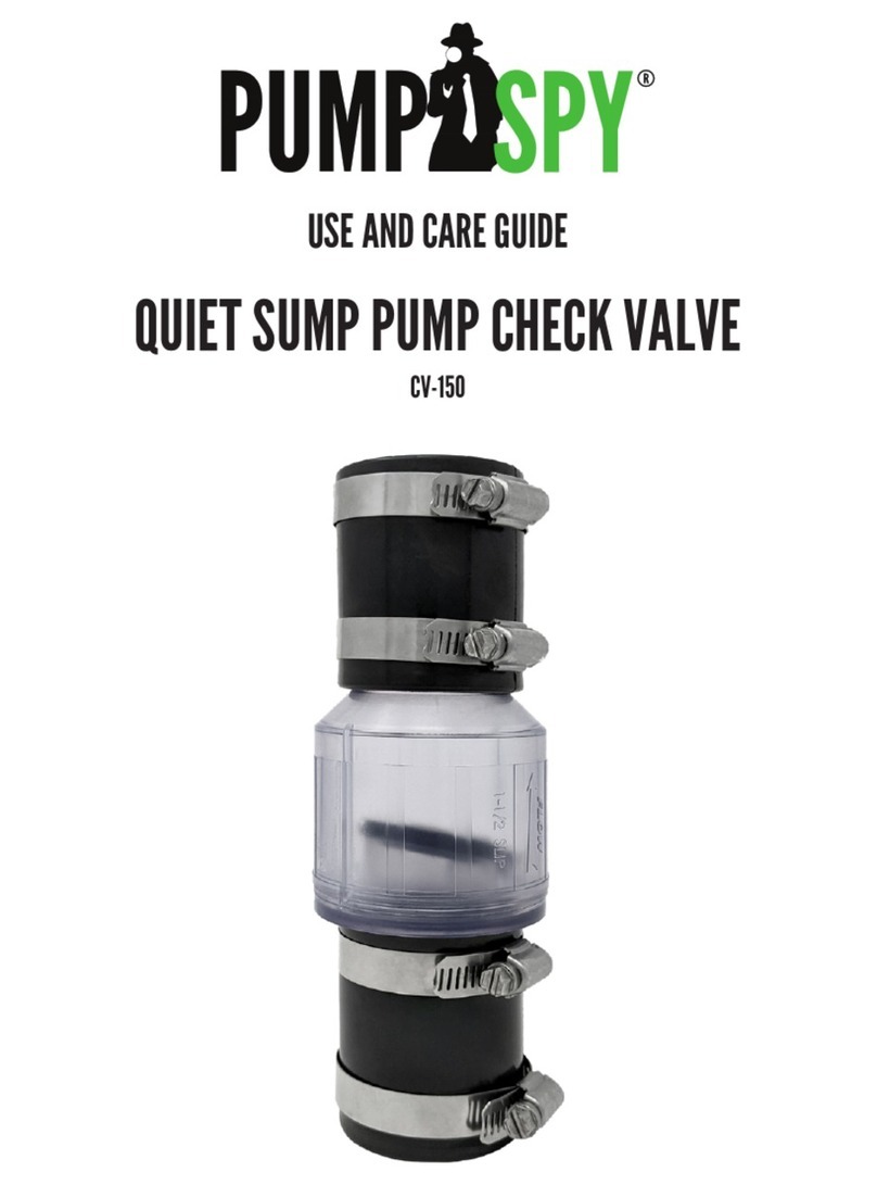
5.Attach a check valve (sold separately) to the top
of the discharge pipe.A check valve is required for proper
operation of system.
The remainder of the discharge pipe installation will vary
depending on individual circumstances. Using sound plumbing
practices, route the discharge pipe to an exterior wall by the
shortest path. Keep turns to a minimum because they reduce
ow output of the pump.
The PumpSpy™Backup Pump can be installed with a separate discharge line (Method 1), or
connected to an existing discharge line (Method 2).
FIGURE 1- Separate discharge line
INSTALLATION
© PumpSpy Technology, LLC Questions? Call Tech Support: 515.999.6935
WARNING
The PumpSpy System requires a 12V Deep Cycle Battery with a minimum
75AMP/HR rating. AGM Battery is strongly recommended.
BEFORE INSTALLING BACKUP PUMP

METHOD 2 (Connecting to existing discharge line) -
See Figure 2
If a separate, dedicated discharge is not desired as in Method
1, the Backup Pump can be tied into the main pump’s discharge
pipe by installing a “Y” connector. Two check valves will be
required.
1.This pump has a 1-1/2 in. NPT discharge.
2. Cut a 3 ft. section of 1-1/2 in. rigid PVC pipe.
Glue 1-1/2 in. pipe to a threaded tting.
3. Screw pipe from step 2 into pump discharge.
4. Place the pump with the 3 ft. section of PVC pipe on a solid,
level surface in the sump pit. Do NOT place the pump on a
loose or sandy surface. Small stones or sand may damage
the pump resulting in pump failure.
5.Attach a check valve (sold separately) to the top of the
discharge pipe.A check valve is required for proper
operation of system.
6. Duplicate the discharge piping arrangement for the
primary AC pump if the existing discharge line has to be
adjusted to accommodate a second pump.
7. Glue a 45º elbow to the pipe on the Backup DC Pump.
Glue a “Y” adapter to the pipe on the main pump, as
shown in illustration for Method 2.
8. Glue a short piece of PVC pipe between the 45º
elbow and the “Y”.
THE CHECK VALVES FOR BOTH PUMPS MUST BE INSTALLED BELOW THE “Y” FITTING!
The remainder of the discharge pipe installation will vary depending on individual circumstances. Using sound plumbing
practices, route the discharge pipe to an exterior wall by the shortest distance.
AFTER PLUMBING IS COMPLETED, FOR BOTH METHODS 1 AND 2
Install oat sensors at least 10 in. -12 in. above bottom of sump pit so that the sensors are higher than the normal “on”
level for main pump.
Make sure power wires and hose clamp ends do not interfere with oat switch, pump inlet, or main pump operation. Failure to
position properly may cause improper operation. Position the oat switch so that it will not interfere with any portion of the
plumbing, wiring, or sump pit.
BACK-UP PUMP OPERATION:
1. The backup pump will turn on when either the bottom or top oat sensor rises.
2. The backup pump will keep running for 10 seconds after the oat sensor drops.
3. PumpSpy™will remotely activate the backup pump during system tests at least 3 times per week.
© PumpSpy Technology, LLC Questions? Call Tech Support: 515.999.6935
WARNING! PUMPSPY SYSTEMTESTS MAY OCCUR AT ANY TIME. THE BACKUP PUMP MAY
CYCLE AT ANY TIME WITHOUT NOTICE.

CONNECTING PUMPSPY™ CONTROLLER
1. Install the Primary Sump Pump and Backup Pump using good plumbing
practices. Both the Primary and Backup pumps should set on the bottom of the
basin.
2. Install the switches for the primary pump and backup pump.The ON level of
the lowest backup switch should be approximately 1” higher than the ON level
of the primary sump pump switch.
3. Connect the Backup Sump Pump to the PumpSpy™Controller’s white jack.
4. Connect the backup switches to the PumpSpy™Controller’s color coded
jacks.
5. VERY IMPORTANT! Connect the Main Sump Pump to the AC outlet on
the PumpSpy™controller.
6. Mount the PumpSpy™ Controller’s antenna as high as possible, preferably
attached to a oor joist or external wall. Remove the backing from the
antenna’s mounting tape, and fasten the antenna. Press ALARM MUTE to see
signal strength. Avoid copper pipes, metal conduits, electrical wiring, or other
metal surfaces.
7. Open the battery case and place 12 Volt battery inside.
8. Connect the PumpSpy™controller to the battery. Red to +, Black to -.
Replace and lock lid on case.
9. Plug the PumpSpy™controller into an AC outlet. Consult your local codes
for GFCI requirements.
10. The PumpSpy™system will initialize and boot up. After booting, the
POWER and SYSTEM lights should be GREEN. The DATA light should be
BLINKING RED.
TEST THE SYSTEM IN THIS ORDER! FILL BASIN WITH WATER,
BELOW THE PRIMARY SUMP PUMP’S ON LEVEL. CHECK
PLUMBING FOR LEAKS DURING TESTING.
Lift the lowest Battery Backup switch and hold. Release when the battery
backup pump cycles.The PumpSpy™controller should sound an alarm with the
message Backup On AC On.The SYSTEM light will turn red.
REFILL BASIN WITH WATER.
Lift the switch for the Primary Sump Pump. Release when Primary Pump cycles
for at least 3 seconds.The PumpSpy™alarm will stop and the SYSTEM light will
be green.
The PumpSpy™system will begin data sync and the DATA light will turn
BLINKING GREEN after the registration process is complete at PumpSpy.com
1.
2.
3.
4.
5.
6.
7.
8.
9.
10.
© PumpSpy Technology, LLC Questions? Call Tech Support: 515.999.6935

In order to get the most from your PumpSpy system, activate the PumpSpy Remote
Monitoring Service.The PumpSpy Remote Monitoring Service computers connect
to your PumpSpy System and watch over your system automatically, 24 hours a day.
PumpSpy collects operating data on your sump pumps and battery and then analyzes
this information to make sure your pumps are always in top working condition.The
PumpSpy Remote Monitoring Service activates and tests your pumps at least three
times per week.
IF A PROBLEM IS DETECTED AT ANY TIME,THE PUMPSPY SYSTEM
WILL SEND AN ALERT TOYOUR EMAIL AND MOBILE PHONE.
You can have alerts sent to as many people as you like at no extra charge.
YOU MUST COMPLETE ALL PLUMBING AND THE INSTALLATION PROCESS BEFORE
REGISTERING YOUR SYSTEM!THE PUMPSPY MONITORING SERVICE WILL ACTIVATE
AND TESTYOUR PUMPS DURING THE REGISTRATION PROCESS!
1. LOCATEYOUR PUMPSPY SERIAL NUMBER
With your documentation, there is a registration card with your system’s serial number. If you are unable to locate
this document, the serial number is also printed on the side of the PumpSpy System Controller.
2. VISIT WWW.PUMPSPY.COM
Once you are on the website, click the “Login/Activate” button.The website will walk you through the registration
process, step by step.
A valid credit card is required to activate the PumpSpy Remote Monitoring Service.Your card will not be charged until
the 30 day trial period expires.There is no long term commitment and you can cancel the service at any time. For
terms and conditions, visit www.pumpspy.com
ACTIVATE THE PUMPSPY REMOTE
MONITORING SERVICE
TROUBLESHOOTING
For additional help, visit the FAQ at pumpspy.com or call 515.999.6935
PROBLEM POTENTIAL CAUSE POSSIBLE SOLUTION
WARNING! Always disconnect the pump from the electrical power source BEFORE handling
or servicing.
Backup Pump will not run
Data light blinks red
No Primary Pump Cycles
recorded
Loose connections
Low or defective Battery
Float Switch is restricted
Unit is not registered
Poor cell signal
Subscription Suspended
Primary Pump not connected
Make sure all connections to Controller are secure
Check battery and replace if necessary
Make sure the oat switch is not obstructed by wires or debris
Register unit online at pumpspy.com to start data sync
Move antenna to better location. Press ALARM MUTE to see
signal strength.
Logon to pumpspy.com and update payment method
Plug Primary Sump Pump into AC outlet on PumpSpy™
Controller
© PumpSpy Technology, LLC Questions? Call Tech Support: 515.999.6935

LED STATES
POWER Green
Red
AC Power is on
AC Power not available
SYSTEM Green
Red
No current alerts
One or more alerts are active
DATA Green Blink
Red Blink
System is connected to PumpSpy Remote Monitoring Service
System is NOT connected to PumpSpy
INFORMATION CENTER LCD MESSAGES
System OK Displayed when no alerts are active.
Power Fail Displayed when no alerts are active.
Backup On/Pwr Displayed when backup pump cycles with AC power available for primary pump. (Possible main pump failing)
Hi Water in Pit Displayed when high water oat sensor is triggered.
Main FS Stuck On Displayed when primary pump runtime exceeds normal value.
Backup FS Stck On Displayed when backup pump runtime exceeds normal value.
Voltage Low Displayed when battery voltage drops below 11.4 volts (50% discharged)
Voltage Critical Displayed when battery voltage drops below 10.4 volts (90% discharged)
Primary Hi Amps Displayed when primary pump current exceeds baseline amp reading by 50%
System Error Displayed when alarm for an alert is muted.
Sig Strgth:xx Display of signal strength as read from cellular module (press mute button)
Displayed when PumpSpy Monitoring Service initiates a system test
Reading Battery Displayed when unit measures battery voltage during self test
Displayed when system sends alert or self test results to PumpSpy
Host Data Valid Displayed when valid command is received from PumpSpy
© PumpSpy Technology, LLC Questions? Call Tech Support: 515.999.6935
Data > Host
Start Autotest
ALARM MUTE BUTTON
• Clears the alert message displayed on the information center LED
• Silences the alarm for 24 hours

Limited Three-Year Warranty
WHAT THIS WARRANTY COVERS
When used and maintained in normal use and in accordance with the Installation and Operating Instructions, your
PumpSpy™ product is warranted against original defects in material and workmanship for a full three years from
date of purchase (the “Warranty Period”). During the warranty period, PumpSpy™will repair or replace at no cost
to you, to correct such defects in products found upon examination by PumpSpy™to be defective in materials or
workmanship.
WHAT THIS WARRANTY DOES NOT COVER
This warranty does not cover use of the product in a non-residential application, improper installation and/
or improper maintenance of the product, damage due to misuse, acts of God, nature, vandalism or other acts
beyond the control of PumpSpy™, owner’s acts or omissions, use outside the country in which the product was
initially purchased and resales of the product by the original owner.This warranty does not cover pick up, delivery,
transportation or house calls. However, if you mail your product to PumpSpy™for warranty service, cost of shipping
will be paid one way.This warranty does not cover products purchased from a party that is not an authorized retailer,
dealer, or distributor of PumpSpy™products.
OTHER IMPORTANT TERMS
This warranty is not transferable and may not be assigned.This warranty shall be governed and construed under
the laws of the state of Ohio.The warranty period will not be extended by any replacement or repair performed
under this warranty.THIS WARRANTY IS THE EXCLUSIVE WARRANTY AND REMEDY PROVIDED BY PumpSpy™.
ALL OTHER WARRANTIES, EXPRESSED OR IMPLIED, INCLUDING WARRANTIES OR MERCHANTABILITY OR
FITNESS FOR PARTICULAR PURPOSE ARE DISCLAIMED. IN NO EVENT WILL PumpSpy™BE LIABLE FOR ANY
SPECIAL, INDIRECT, INCIDENTAL OR CONSEQUENTIAL DAMAGES OF ANY KIND OR NATURE TO OWNER
OR ANY PARTY CLAIMING THROUGH OWNER WHETHER BASED IN CONTRACT, NEGLIGENCE,TORT OR
STRICT PRODUCTS LIABILITY OR ARISING FROM ANY CAUSE WHATSOEVER. Some states do not allow for the
exclusion of consequential damages, so the above exclusion may not apply to you. This warranty gives you specic
rights.You may also have others that vary state to state.
Installed by:
Date of Installation:
Model : PS 1000
Serial Number:
© PumpSpy Technology, LLC Questions? Call Tech Support: 515.999.6935
83019-03
Table of contents
Other PumpSpy Water Pump manuals
Popular Water Pump manuals by other brands

dosatron
dosatron ANIMAL HEALTH D25AL2-N owner's manual

Additel
Additel ADT920 user manual

Pfeiffer Vacuum
Pfeiffer Vacuum HIPACE 350 operating instructions

Raider
Raider Garden Tools RD-WP 1300 user manual

Grundfos
Grundfos CRE Series Installation and operating instructions

Harvest TEC
Harvest TEC 9214 owner's manual

Hurco
Hurco Old Faithful Pumper Reference Manual and User Guide

nedis
nedis WIFIWP10GY quick start guide

Shibaura
Shibaura FK500-A owner's manual

Grundfos
Grundfos UNILIFT AP35B Installation and operating instructions

Silverline
Silverline 104616 quick guide

Wilo
Wilo CronoLine-IL Installation and operating instructions