MYERS E54-30 Installation instructions

26850A003
1
E54-30 Part No. 26866F000
E54-30L Part No. 26866F010
E70-23V Part No. 26866F100
E70-23VL Part No. 26866F110
E80-20V Part No. 26866F300
E80-20VL Part No. 26866F310
E110-14 Part No. 26866F200
E110-14L Part No. 26866F210
E Series
Reciprocating Pump (Shaft Drive)
Safety Instructions and Service Manual
CALL 1-800-577-8111 FOR SALES AND SUPPORT

26850A003
2
Table of Contents
SPECIFICATIONS ............................................................................................................................... 3
DIMENSIONS ...................................................................................................................................... 4
BELT DRIVE (Dimensions) .................................................................................................................. 4
STARTING THE PUMP ........................................................................................................................ 4
SUGGESTED MAINTENANCE SCHEDULE ..................................................................................... 5
LUBRICATION ..................................................................................................................................... 5
ADDITIVES FOR CRANKCASE OIL .................................................................................................. 5
SERVICING THE PUMP:
REMOVING PISTON ...................................................................................................................... 5
INSTALLING THE PACKING ............................................................................................................ 6
REMOVING THE CYLINDERS ...................................................................................................... 6
CYLINDER INSTALLATION .......................................................................................................... 6
REMOVING THE SEATS: Wing Guided Valves ............................................................................. 6
REPLACEMENT OF VALVES ........................................................................................................ 7
REPLACING PISTON ROD SEALS .............................................................................................. 7
REMOVING CRANKSHAFT AND PINION SHAFT ...................................................................... 7
REPLACING PINION SHAFT & SHIMMING BEARINGS ............................................................ 8
REPLACING CRANKSHAFT & SHIMMING BEARINGS ............................................................. 8
RECONDITIONED CRANKSHAFTS ............................................................................................ 9
SERVICING CONNECTING LINKS .............................................................................................. 9
CROSSHEAD AND PISTON RODS ............................................................................................. 9
RECOMMENDED TORQUE (Foot-pounds) .................................................................................. 9
VALVE LIFTERS ........................................................................................................................... 10
SERVICE CHART & TROUBLE-SHOOTING ............................................................................. 11
CROSS-SECTIONAL VIEWS OF PUMPS:
SIDE VIEW – PRE JUNE 1, 2008 E70-23, E80-20 ..................................................................... 14
SIDE VIEW – POST JUNE 1, 2008 E70-23V, E80-20V ............................................................. 15
POWER-END ............................................................................................................................... 16
PARTS LIST ................................................................................................................................. 17
CALL 1-800-577-8111 FOR SALES AND SUPPORT

26850A003
3
SPECIFICATIONS
NOTE: Flow (GPM/LPM) based on 100% volumetric efficiency. Horsepower and kilowatts required are based on 85% overall efficiency.
Horsepower requirements are at Myers pump input shaft. The efficiency of the hydraulic pump, hydraulic motor, etc. must be considered to
determine horsepower required to drive complete system.
GPM
1800 PSI
2100 PSI
2400 PSI
2700 PSI
3000 PSI
LPM
124 BAR
145 BAR
165 BAR
186 BAR
207 BAR
30 37 43 49 55 62
113 28 32 36 41 46
36 44 52 59 66 74
136 33 39 44 49 55
42 51 60 59 79 86
158 38 45 51 59 64
48 59 69 79 89 98
181 44 51 59 66 73
54 66 79 89 100 111
204 49 59 66 75 83
E-54-30
1417
1620
1823
Horsepower/Kilowatts Required For:
RPM
1012
1215
GPM
1900 PSI 2000 PSI 2100 PSI 2200 PSI 2300 PSI
LPM
131 BAR 138 BAR 145 BAR 152 BAR 159 BAR
30 39 41 43 45 47
113 29 31 32 34 35
40 52 55 57 60 63
151 39 41 42 45 47
50 65 69 72 75 80
189 48 51 54 56 60
60 78 82 86 90 95
227 58 61 64 67 71
70 91 96 100 105 110
265 68 72 75 78 82
Horsepower/Kilowatts Required For:
RPM
914
1143
E70-23V
1371
1600
1828
GPM
1200 PSI 1400 PSI 1600 PSI 1800 PSI 2000 PSI
LPM
83 BAR 97 BAR 110 BAR 124 BAR 138 BAR
40 33 38 44 49 55
151 24 29 33 37 41
50 41 48 55 62 69
189
31
36
41
46
51
60 49 58 66 74 82
227 37 43 49 55 61
70 58 67 77 86 96
265 43 50 57 64 72
80 66 77 88 99 110
303 49 57 65 74 82
Horsepower/Kilowatts Required For:
RPM
914
1143
E80-20V
1371
1600
1828
GPM
800 PSI
1000 PSI
1200 PSI
1400 PSI
LPM
55 BAR
69 BAR
83 BAR
97 BAR
70 38 48 58 67
265 28 36 43 50
80 44 55 66 77
302 33 41 49 57
90 49 62 74 86
340 37 46 55 64
100 55 69 82 96
378 41 51 61 72
110 60 75 90 106
416 45 56 67 79
Horsepower/Kilowatts Required For:
E110-14
1487
1652
1817
RPM
1157
1322
E54-30 E70-23V E80-20V E110-14
RATED MAX CAPACITY (G.P.M.) 54 70 80 110
PINION SHAFT RPM @ MAX. CAPACITY 1823 1807 1828 1817
PRESSURE RATING (PSI) 3000 2300 2000 1400
CYLINDER BORE DIA. (INCHES) 1.750 2.000 2.125 2.500
PISTON STROKE LENGTH (INCHES)
GEAR REDUCTION RATIO
TEMPERATURE RATING, MAX.
SUCTION SIZE (INCHES) NOMINAL
DISCHARGE SIZE (INCHES) NOMINAL
INPUT SHAFT DIAMETER (INCHES)
KEYWAY (INCHES)
WEIGHT (Lbs.)
FLUID-END CASTING MAT'L
VALVE MAT'L
VALVE SPRING MAT'L
CYLINDER MAT'L STAINLESS STEEL/CERAMIC OXIDE COATING
525
DUCTILE IRON
17-4 PH with POLYURETHANE INSERT
STAINLESS STEEL
3" NPT
1 1/4 NPT
1.6250/1.6245
3/8 X 3/16
TRIPLEX PUMP MODELS
3.75
3.95 to 1
160F
CALL 1-800-577-8111 FOR SALES AND SUPPORT

26850A003
4
GENERAL INSTRUCTIONS
CAUTION: Positive Displacement Pumps must
have a proper size and operable type of pressure
regulating valve or pressure relief valve piped into
the discharge line. This is mandatory to prevent
damage to pump and piping or possible injury to
personnel. DO NOT install any valves or shut-off
devices in the bypass line from pressure regulator
to tank or supply.
BELT DRIVE SEWER CLEANERS
With belt drives, pulley on both engine and pump should
be located as closely as possible to bearing to reduce
bearing and shaft bending loads. Make sure that all
bolts, nuts, set screws, and keys are properly tight-
ened.
PULLEY LOCATION ON PUMP AND MOTOR SHAFT
DIMENSIONS
A B C D E F G
Diameter of
Mounting Hole
21 36.25 17 14 7.5 16 10.38 0.75
533.4 920.75 431.8 355.6 190.5 406.4 263.7 19.05238
Weight Lbs.
(Kg)
Dimensions in Inches (Millimeters)
525
STARTING PUMP
A. Before Starting:
1. Read all instructions carefully.
2. Fill pump crankcase with recommended oil to
level mark on oil saber. Oil recommendations are
covered in lubrication section of pump instruc-
tions.
3. Replace all drain plugs in pump and piping.
4. Inspect tank to be sure that no foreign material is
in tank or suction line.
5. Fill tank at least half full or connect suction to
water supply. Open valve (if present) in suction
line. Avoid prolonged dry operation which may
cause excessive wear on cylinders and piston
packing. Be sure that an operating pressure
gauge is located in discharge line.
6. Make sure all valves, including spray gun or
nozzles, are open in discharge line. Spray gun
may be anchored to discharge back into tank.
7. Completely back off pressure adjusting screw on
pressure regulating valve.
B. Starting the Unit:
1. After starting, close discharge valve or spray gun
slowly while watching pressure gauge to make
sure relief valve or unloader is operating properly.
2. Adjust relief valve or unloader to desired pres-
sure. See regulator instructions.
3. Cycle nozzles or gun on and off to be sure that
pressure adjustment and regulator operation is
satisfactory.
NOTE: Nozzle capacity should not exceed 90% of
pump capacity for satisfactory regulator operation.
AVOID FREEZING by draining all water from pump and
system in cold weather.
A
F
G
B
CALL 1-800-577-8111 FOR SALES AND SUPPORT

26850A003
5
SUGGESTED MAINTENANCE SCHEDULE
OPERATION INTERVAL
Check oil level Daily
Drain and change oil 300 hr. (1)
Replace piston packing 500 hr. (2)
Inspect valves and springs 500 hr. (3)
Inpsect connecting link bearing inserts 1000 hr. (4)
Inspect crankshaft tapered roller bearings 2000 hr.
(1) Drain at operating temperature to prevent contamina-
tion from setting.
(2) Inspect frequently for leakage; replace before 500
hours if any cylinder exceeds 10 drops per minute
leakage. Packing may not look badly worn but will
often be shiny and hard and won’t seal well.
(3) Replace if cracks and heavy wear are present.
(4) Replace at first signs of fatigue or wear to prevent
damage to crankshaft.
LUBRICATION
Fill gear case with Mobilgear 630 or equivalent 80W90
oil to capacity listed in chart. Note oil level on oil
dipstick, and maintain at this level.
NOTE: Slow speed operation of Myers Reciprocating
Pumps can be accomplished by adding additional oil to
the crankcase (see chart). The higher level compen-
sates for lack of splash lubrication at slow speeds.
Some slight leakage may occur around crossheads and
dipstick/vent area with additional oil.
For further information, please consult the factory.
IMPORTANT:After first 30 hours of operation drain oil
from gear case (preferably drain at operating tempera-
ture), replace plug and refill crankcase with new oil as
above. Change oil every 300 hours thereafter. Check
oil level daily and add oil as needed.
ADDITIVES FOR CRANKCASE OIL
Use of Molybdenum Disulfide (MoS2) is optional as an
additive to the petroleum-based gear case oil in back
geared pumps and speed reducers manufactured by
Myers. Do not use this additive with synthetic oil. It
appears to be so effective in reducing wear and friction
that power train life may be doubled between overhauls.
Volume of liquid MoS2concentrate required at various speeds
VOLUME MoS2, CONCENTRATE
PINION RPM GEAR CASE OR DISPERSION “M” FOR
RANGE CAPACITY 5% 10%
1600 - 1800 6½ Qts. 7 Fl. Oz. 14 Fl. Oz.
1000 - 1599 6½ Qts. 9 Fl. Oz. 18 Fl. Oz.
600 - 999 6½ Qts. 10 Fl. Oz. 20 Fl. Oz.
The MoS2fluid concentrate is marketed by Dow Corning,
Phone (517)-496-6000 or www.molykote.com/iam under the
designation “Molykote M Gear Guard.” Several other
brands are available. Follow instructions of manufacturer.
SERVICE
CAUTION: Disengage clutch, disconnect electrical
leads to motor, or remove spark plug leads on engine.
Following work on any internal pump parts, it is important
to tighten all clamps, caps and assemblies to specific
torque ratings, refer to Recommended Torque chart.
CAUTION: Also inspect cylinders for linear grooving by
running your thumbnail circumferentially around bore of
cylinder. If any grooving is detected also replace cylinders.
New packing will rapidly cut or wear out in grooved cylinders.
SERVICE
CAUTION: Disengage clutch, disconnect electrical leads to
motor, or remove spark plug leads on engine. Following
work on any internal pump parts” it is important to tighten all
clamps, caps and assemblies to
specific torque ratings, ‘refer to Recommended Torque
chart.
REMOVING PACKiNG
Move assembly to front end of cylinder (top dead center).
Remove valve assembly if required to provide clearance.
Remove cap screw with an Allen wrench. (Allen wrench,
Part No. 8574A11). Retract piston rod and insert tool as
shown. Pull packing assembly out or push by rotating
crankshaft by hand.
CALL 1-800-577-8111 FOR SALES AND SUPPORT

26850A003
6
CAUTION: Also inspect cylinders for linear grooving by
running your thumbnail circumferentially around bore of
cylinder. If any grooving is detected also replace
cylinders. New packing will rapidly cut or wear out in
grooved cylinders.
INSTALLING PACKING
Assemble V-Rings onto stud as shown. Lubricate the
outside of the assembly with Molykote or other grease
for ease in insertion – do not use a graphite type grease.
When installing each V-Ring assembly, rotate crankshaft
until piston rod is at forward position. Place copper
gasket 5030A128 in position in stud using a small
amount of Permatex to hold in place. NOTE: Apply
Loctite RC35 to capscrew prior to piston installation.
Follow instructions on label and make certain threads in
piston rod are clean and free of any grease or oil.
Assemble capscrew, etc., into piston assembly and
push into cylinder. Torque the capscrew to 50 ft. lb. using
a hexagonlal socket attachment 3/8" across flats.
REMOVING CYLINDERS, (Fig. 5)
1. First remove packing as outlined previously.
2. Rotate crankshaft until piston rod is in rear position.
3. Insert puller (3) through inside of cylinder and pilot over
piston rod.
4. Insert disc (4) into slots on puller (3).
5. Slip plate (2) over threads on puller (3) as shown.
6. Screw nut (1) on thread on puller (3) and snug up.
7. Tighten nut (1) until liner breaks loose.
8. Loosen nut (1) and slip disc (4) out of slots.
9. Remove puller (3) and repeat to remove other
cylinders.
CYLINDER INSTALLATION
Reasonable care and judgment should be used when
installing the new cylinder. Clean out any accumulation
of loose rust or corrosion in cylinder body. Install a new
O-ring in groove on tapered portion of cylinder, lubricate
O-ring with oil or grease for ease in insertion. Position
cylinder carefully by hand to avoid cutting the O-ring.
Drive into position firmly with a wooden block and mallet.
Never use a hydraulic press; excessive force can cause
damage and make cylinders very difficult to remove for
later replacement.
REMOVING SEATS: Wing Guided Valves
A. First remove valve caps, (61) and cylinder
caps, (72) which provide access to suction and
discharge valves. Remove the stainless steel cage
which serves as a valve guide and spring retainer.
Remove cage (65), spring (66), and valve (67), from
the pump fluid end. (Fig. 6)
.Suction valve seats are removed as above except
two stud lengths are joined using coupling
Fig. 6
1¾”,
Fig. 5
SUCTION & DISCHARGE VALVE ASSEMBLY
Part No. (TS18-AR0-AC0714)
CALL 1-800-577-8111 FOR SALES AND SUPPORT

26850A003
7
REPLACEMENT OF VALVES
A. Inspect tapered valve seat bore in fluid end for rust
and wipe out excess with a rag. Place a new lower
seat in tapered hole. With a hardwood round dowel,
drive lower seat firmly into place with a hammer.
Repeat for upper seat being sure to also inspect the
tapered bore in housing for rust.
IMPORTANT: Both the valve seat O.D. and tapered
bore I.D. MUST BE VERY CLEAN.
B. Reassemble valve, spring, and cage as shown in
Fig. 6, Be sure that springs are in correct location.
When upper and lower valve seats are the same
size, the heavier spring (larger diameter wire) is
always installed on upper or discharge valve.
NOTE: Be sure that cage is tightened onto valve seat.
C. Inspect seals on valve and cylinder caps. Replace if
seals show signs of wear, or “nibbling.” Lubricate
seals and replace cap, bar and nuts. Torque cap
covers nuts to specification shown in torque chart.
CAUTION: Do not use a hand or arbor press to install
valve seats. It is possible to crack cylinder body with
excessive pressure.
REPLACING PISTON ROD SEALS
Fig. 8
The rod seal assembly contains two seals, two oil seals
with lips facing power end. The oil seal can be replaced
without taking the fluid end off by removing the cylinder
and piston to allow access for oil seal housing. Unscrew
two Allen screws and place into the other two tapped
holes. Gradually screw them in to push oil seal housing
off the retainer. After assembling new seals in oil seal
housing an assembly thimble should be used on end of
crosshead rod for sliding oil seal housing back into
retainer. Check gasket, replace if damaged.
An assembly thimble should be used on small end of
the piston rod to expand sealing edge as it is pushed on.
“Figure 9” illustrates an assembly thimble being placed on
the end of the rod. “Figure 10” shows a recommended
thimble for installation of oil seals. The thimble should be
machined from high carbon steel and polished on the
exterior to reduce possibility of seal lip damage.
REMOVING CRANKSHAFT AND PINION
SHAFT
Remove piston assemblies. Remove connecting link
caps and move the link-crosshead assembly as far
forward as possible.
IMPORTANT: Note the markings on the connecting links
and caps; these parts are not interchangeable and must
be reassembled in their original positions.
Wedge a ¾” board between crankshaft gear and gear
case so that crankshaft will be held in place against
pinion shaft. Remove both crankshaft bearing caps.
(See Fig. 11). Hold crankshaft at ring gear and left-hand
link journal (to prevent dropping into bearing bores),
remove from gear case by moving crankshaft to right until
left end can be swung free.
To remove pinion shaft, remove bearing cap bolts.
Next, using a lead or rawhide hammer, tap the end of
42 Oil Seal
41 Retainer
Fig. 10
37 Housing
Fig. 9
CALL 1-800-577-8111 FOR SALES AND SUPPORT

26850A003
8
REPLACING CRANKSHAFT AND
SHIMMING BEARINGS
Press the bearing cups into the caps. Place one cap
into position on the right side with cap screws engaged
about one turn; install crankshaft (left end first, then
push both bearing caps into place. Extreme care should
be exercised to avoid damage to gear teeth, bearings,
and link journals.
For quiet operation and long life, the crankshaft and
Good performance of tapered roller bearings on
a shaft require that correct shaft end play first be
made by shimming. This insures that uneven
heating, as encountered during warm-up, will not
overload the bearings, and that after all parts are
heated to approximately the same temperature the
resulting end play will be correct. Shouldered roller
bearings also require correct shimming to insure
that the shoulder will properly locate the shaft and
yet not bind.
pinion shaft extension to remove bearing cup at opposite
end. After removing pinion shaft, the remaining bearing
cup can be removed by gently tapping against the
peripheral edge of the cup with a brass rod.
Fig. 11
REPLACING PINION SHAFT AND
SHIMMING BEARINGS
After installing the link-crosshead assemblies and
moving them toward the fluid end as far as possible,
tap right-hand pinion shaft bearing cup into position
using the bearing cap. Make sure that the spacer is
properly seated on drive end of pinion shaft (the curve
side should match the fillet radius of pinion shaft).
Place pinion shaft in position and tap left-had bearing
cup into place.
A. Cover shaft keyway with vinyl tape to protect lip of
oil seal, slide on the open bearing cap to which has
been added approximately .030 shim, tighten the
four cap screws to recommended torque.
B. Put on other cap using total shim thickness known
to be more than needed so that resulting end play is
greater than required. Tighten cap screws holding
pinion or crankshaft caps to gear case. Rotate pinion
shaft back and forth and apply about 15 lbs. axial
force to properly seat tapered rollers. Measure end
play by using an indicating gage in a manner shown
in Fig. 12.
C. Subtract recommended end play (.005-.009) from
actual end play as found above. This is the amount
of shim that must be removed. After excess shim
thickness has been removed, replace caps and
retighten cap screws. Again measure end play. If
end play is not within limits recommended, add or
subtract shims as required.
Fig. 12
Fig. 13
CALL 1-800-577-8111 FOR SALES AND SUPPORT

26850A003
9
bearings must be installed with .003 to .005 in preload;
the following procedure will provide an accurate adjust-
ment. Before starting, loosen the four cap screws on the
pinion shaft bearing cap.
A. Place about .045 shim on the right crankshaft
bearing cap, tighten the five cap screws.
B. Install the left cap without shims, secure with two
cap screws positioned exactly as shown in “Fig.13”.
Torque the two cap screws at 13 foot pounds, rotate
the crankshaft, retorque the cap screws. Do this
three times to properly seat the tapered roller
bearings.
C. Measure (adjacent to the cap screws) the shim gap
remaining between the bearing cap and the gear
case.
D. The required shim thickness for this cap is equal to
the average gap measurement plus .022”.
E. Insert correct shim thickness under left bearing cap
and tighten cap screws.
F. Install connecting links and caps; note the mark-
ings; torque cap screws to 40 ft. lb.
G. IMPORTANT - Check for adequate side clearance
of links on crankshaft. Some shims must be moved
from one end of the crankshaft to the other until
sideways movement of all links can be seen.
H. Check torque of cap screws on all bearing caps.
RECONDITIONED CRANKSHAFTS
When the crank throws are only slightly damaged, such
as small surface grooves cut part way around the
bearing surface, they can sometimes be reconditioned
for further use. This can be done by sandpapering and
polishing until all ridges are completely removed. The
final polishing operation should be with very fine emery
cloth. If the surface is badly damaged, the crankshaft
can often be salvaged by “metalizing” the crank throw
and then regrinding and polishing to the original diam-
eter of 3.1240-3.1245”.
SERVICING CONNECTING LINKS
The connecting rod link is furnished with replaceable
split sleeve bearing inserts at the crank throw. It is
never practical to attempt to refit connecting links to the
crankshaft bearings by filing or grinding the mating
faces of the link cap where it contacts the link. Always
be sure that the proper side of the link is placed upward
when attaching it to the crankshaft. The upper side
contains an oil hole at the crosshead end of the link.
This oil hole must be up to allow proper oil feeding to
the crosshead pin bushing. The wrist pin is press-fitted
into crosshead and slip-fitted through the bronze
bushing. Use arbor press instead of hammering the
wrist pin to force it in. Check to see if link is free to
Fig. 14
rotate after the wrist pin is pressed in. Make sure that
either side of wrist pin does NOT protrude beyond the
crosshead.
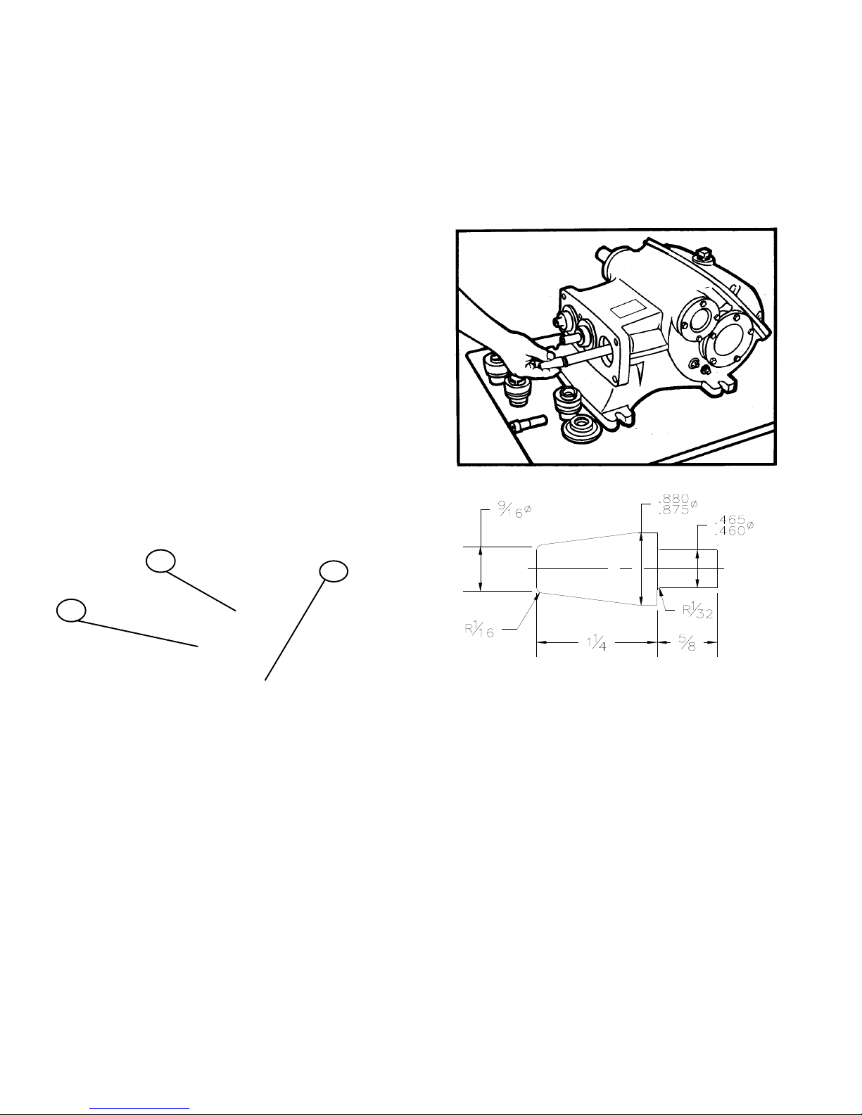
The crosshead end of the connecting link is fitted with a
bronze bushing. When new replacement links are
obtained, these bushings are reamed to the proper size
for immediate installation. If the bushing only is
replaced, it may be necessary to ream the new bushing
to the proper inside diameter after it is pressed into the
link. When placing the bushing on the link be sure that
the oil holes in the bushing and link will be in line after
the bushing is pressed into position. Fig. 14 shows the
proper diameter to which the bushing must be reamed
for proper seating of the crosshead pin. Note that the
ream diameter must be parallel to the I.D. of the sleeve
bearings within 0.001” T.I.R.
CROSSHEAD AND PISTON RODS
Repair parts for the crosshead and piston rod are
supplied only as a complete unit. If either of these
parts becomes worn it is necessary to replace both the
crosshead and piston rod. Under normal conditions a
crosshead will not wear nor will the bore of the crank-
case wear to the extent that oversize crossheads will
be required. If extreme wear does occur, it will be due
to severe damage from the lack of oil or a fairly large
metal object scoring the crosshead bore. A clearance
of .002” to .004” is standard for the crosshead. The
parts can wear until considerably more clearance than
this exists before harmful operation will occur.
RECOMMENDED TORQUE (Foot-pounds)
FASTENER LOCATION
Link Bearing Caps 40
Crankshaft End Caps 20
Pinion Bearing End Caps 20
Cap Screw, 3/4
(Fluid End to Power End) 250
Cap Screw, 5/8
(Fluid End to Power End) 150
CALL 1-800-577-8111 FOR SALES AND SUPPORT

26850A003
10
VALVE LIFTERS
Optional valve lifter assemblies are available, Part No.
13014A004K, three are required per pump. The purpose of
these are to lift the inlet valve guide to allow liquid to drain from
the cylinder chamber. This will prevent damage to the pump as
a result of freezing of the pumped liquid.
To operate, one of the 3” NPT pipe plugs in the inlet cham-
ber should be removed. Then the knob of the lifter is turned to
cause upward movement of the lifter stem that contacts and
raises the valve guide. Liquid will then drain from the cylinder
chamber, into the inlet chamber and then out of the pump.
CALL 1-800-577-8111 FOR SALES AND SUPPORT

26850A003
11
Explanation of the Service Chart
1. Pump priming is usually not necessary when the
pump is installed correctly. However, there are
certain unusual conditions which may make it
necessary to prime the pump to get the pumping
action started. Priming will be required under
conditions where it is impossible for the piston to
displace the air in the pump and replace it with
water. This could be caused by a high suction lift
(high from the water supply to the pump), the valves
being stuck on the seat, such as after pumping a
sticky fluid, or it might be caused by valves sticking
due to extreme corrosion of the valves and seats.
A pump will not prime readily if someone has
tampered with the valve springs causing them to
exert undue pressure of the valve plates against the
valve seats. When the pump appears to need
priming this condition can be checked by pouring
water into the cylinder body through one of the valve
cap openings or into the pump discharge opening at
the same time operating the pump to work the water
into the cylinder and valve passages.
2. Frequently a gate valve is installed in the suction
line between a tank or pressure line and pump
sediment chamber. This valve is usually installed in
the line to shut off the supply source for cleaning
sediment chamber or for pump repairs.
If this valve is closed or even partially closed it will
interfere with the flow of water to the pump suction
to such an extent that the pump will not perform to
full capacity. If the valve is partially closed it may
cause severe knocking and vibration of the pump
because the water cannot flow into the cylinder
cavities fast enough.
3. A sediment chamber should be installed in the
suction line between the gate valve and the pump
suction.
The strainers in these sediment chambers are of
more than adequate capacity to allow a free flow of
the liquid to the pump. However, because of its
normal function of collecting sediment the strainer
may become severely clogged and in some cases,
it will completely stop the flow of liquid to the pump.
The length of time the pump may operate before it
is necessary to clean the strainer will depend upon
the type of liquid pumped. After the pump has been
used a short period the operator will soon become
familiar with the amount of running time between
strainer cleanings.
WARNING: THIS PUMP MUST BE INSTALLED WITH A PRESSURE RELIEF VALVE IN DISCHARGE LINE
SERVICE CHART
SERVICE PROBLEM
A. Failure of pump to build pressure with discharge closed
B. Failure to hold pressure with discharge open
C. Pump is noisy
D. Pump gets hot
E. Pressure gauge shows abnormal fluctuation
POSSIBLE CAUSE OF PROBLEM E D C B A
1. Pump not primed X
2. Valve closed in suction line X X
3. Suction line or sediment chamber clogged X X X
4. Air leak in suction line X X X
5. Pressure regulator valve badly worn or not properly adjusted X X
6. Broken valves or springs X X X
7. Pump packing or valves badly worn X X X
8. Pressure regulator bypassed by open #1 valve X X
9. Pump cylinder body cracked X X X
10. Water in crankcase X
11. Worn connecting link inserts or wrist pin bushings X X
12. Lack of oil in crankcase X X
13. Foaming mixture in tank X X X
14. Regulator plunger sticking X
15. Foreign matter under pump valve X X X
16. Loose plunger rod X
17. Improper preload of crankshaft bearings X X
CALL 1-800-577-8111 FOR SALES AND SUPPORT

26850A003
12
4. Any piston pump, when operated at high pressure
will not operate satisfactorily or quietly if a mixture
of air and water is allowed to enter the pump
suction. For this reason, a small air leak in the
suction line will cause the pump to knock and
vibrate excessively. This holds true only for a small
air leak which allows the pump to draw a certain
amount of water mixed with air on each stroke of
the piston. A large air leak will cause the pump to
lose prime after which it cannot be reprimed until the
air leak is stopped. Air leaks may occur at the
joints of the suction line piping, at the gate valve in
the suction line, at the gasket sealing the cap on
the sediment chamber or by a crack in the suction
wall of the cylinder body, such as might be caused
by freezing if the pump is not properly drained in
freezing weather. There is also a definite possibility
of air drawing past the packing on the suction stroke
if the packing is badly worn.
5. If the pressure regulator internal bypass valve is
badly worn it will allow too much of the pump
capacity to be bypassed and recirculated back to
the tank. By examining the flow from this valve with
the discharge turned on, it can be determined
whether or not the valve is worn. If a heavy flow
continues when the discharge is turned on, it is
usually a good indication that the valve is badly
worn and should be replaced or that something is
lodged under the valve holding it open.
6. A broken pump valve or spring will often prevent
one cylinder from functioning properly. Very rough
pulsing discharge, a knocking sound, and a loss of
capacity will result. If not repaired promptly, the
rough running pump can cause mechanical damage
to itself or other system components.
7. Badly worn piston cups or valves and valve seats
will cause a serious drop in pump capacity. This will
be indicated by a drop in pressure when guns are
turned on. Worn piston cups are very easy to detect
because of the water leakage. The piston cup
should be replaced just as soon as this leakage is
noticed. If it is allowed to continue some of the
water may work past the piston rod seals into the
pump crankcase. Water in the pump crankcase will
cause severe corrosion of the bearings causing
rapid wear. Worn valves can only be detected by
visual examination of each valve assembly. The
most prevalent cause of valve wear is the use of
highly abrasive liquids which will cause the valve
and valve seat to wire cut. The cut starts as a very
small groove but increases very rapidly once the
valve starts to leak through this groove. If the
valves are replaced as soon as they start to show
this cutting action it will prevent the valve seat from
becoming cut in a similar manner and keep the cost
of replacement parts to a minimum.
8. If a portion of the pump delivery is allowed to
bypass because the #1 control valve is not com-
pletely closed there may not be adequate flow to
develop full pressure. This also will cause rapid
wear in the control valve; any excess flow should be
bypassed only by the pressure regulator.
9. Pump cylinder bodies must withstand an extreme
amount of shock and pulsation while the pump is in
operation. If the pump is allowed to freeze, due to
not being drained, the freezing may crack the
cylinder body walls in almost any location. If the
crack should occur on the suction valve or cylinder
portion of the body it may allow a small amount of
air to enter on the suction stroke and cause noisy
operation or a decrease in pumping capacity. If the
crack develops in the walls between the cylinder
cavities or discharge valve cavity it may allow the
water to flow from one cavity to the adjacent cavity
and rob the pump of its effective displacement.
This will not cause noisy operation but will reduce
the pump capacity and may show up as a drop in
pressure when the discharge is open.
10. Water may accumulate in the pump crankcase from
two sources; the most prevalent being leakage of
the cups as explained in paragraph 7. The other
means of accumulation being a condensation of
moisture inside the crankcase due to changes in
weather or the repeated heating and cooling of the
pump due to its normal usage. Pumps that are
used rather consistently and run for a considerable
period of time to heat the oil and other working parts
will not normally accumulate water by condensation.
If the cups are replaced as soon as it starts to leak
it will be impossible for water to enter the crankcase
from this cause.
11. Worn connecting link bearings will only develop
because of unusual or adverse operating conditions.
They will, however, be seriously affected by corro-
sion if water is present in the crankcase and they
will wear out from overheating if the oil is not clean
and of good quality. For this reason we recommend
thorough draining, cleaning and refilling with new oil
at the specified interval and prior to any storage
period. Replace link inserts as soon as any wear is
noticed to avoid damage to crankshaft journals.
Also see paragraph 17 and lubrication instructions.
CALL 1-800-577-8111 FOR SALES AND SUPPORT

26850A003
13
12. Lack of sufficient oil in crankcase can quickly
cause failure of pump power end and result in
extensive repairs. Oil level should be checked
periodically during normal operation as well as when
maintenance work of any nature is performed.
Insufficient oil will first be indicated by excessive
heat and should be corrected immediately.
13. A foaming mixture will sometimes have the same
effect as a small air leak in the suction line. This is
because various quantities of the foam are drawn
through the suction line into the pump disrupting the
normal flow of water.
14. Pressure regulators may become sluggish in action
due to the plunger sticking or fitting too tightly in its
cylinder. This condition may be caused by an
accumulation of chemicals collecting in and around
the plunger, or may be due to excessive corrosion
of the plunger parts. To check this condition,
remove and clean the plunger. After cleaning the
plunger, parts should be covered with a waterproof
grease before assembling.
In some cases there is a tendency for the pressure
regulator to chatter or vibrate excessively. This is
an indication of unstable operation due to nozzling
in the high or low capacity range of the regulator; the
nozzling requirements should be at least 50% and
not exceed 90% of pump capacity.
Due to nozzle wear, the system requirements may
exceed the 90% limit, resulting in cycling or ham-
mering of the regulator. This can readily be checked
by replacing the worn nozzle.
15. If a large piece of foreign matter becomes lodged
between a pump valve and valve seat or if some-
thing of this kind becomes wedged in so that it
prevents the valve from operating normally we can
expect a drastic drop in capacity and considerable
surge or pulsation will be noticed in the discharge
line. To correct a condition of this kind it is usually
necessary to examine each valve in the pump until
the offending condition is located. The use of clean
liquid and seeing that the suction strainer is in
proper condition will prevent trouble of this kind.
16. Noisy pump operation will sometimes be caused by
a piston rod being loose in the crosshead. This will
only become evident after the rod becomes so
extremely loose that some end motion can be found
between the rod and crosshead. A noise of this
kind usually has a regular cadence timed with each
stroke. When this condition occurs it is always
necessary to replace both the rod and the cross-
head.
17. More than the recommended amount of preload to
the crankshaft bearings will reduce bearing life,
require more power, and generate more heat. Less
than the recommended preload may cause a knock
timed with the crankshaft rotation. Check for loose
bolts on the crankshaft end caps or adjust shims to
obtain proper bearing preload.
Worn roller bearings will continue to run for a long
time but will introduce wear particles into the oil
(which can cause other damage), may cause
overheating, and may or may not cause a notice-
able noise. Check oil regularly, check for wear
particles when changing oil.
UNUSUAL CONDITIONS WHICH MAY CAUSE
TROUBLE
Pinion shaft breakage on the drive side of the pump
may be caused by having the pulley or sprocket
positioned too far away from the pump bearing. It may
also be caused by a loose drive chain if the pump is
chain driven.
If the V-belts have a tendency to wear rapidly, it may be
due to having the belt tightener pulley adjusted too far
into the belt, throwing a reverse bend in the belt where it
passes over the pulley. If very much reverse angle
seems necessary to keep the belt tight, other provi-
sions should be made for tightening, such as placing
shims under the pump base or otherwise spreading the
drive centers enough to take up the belt length. On
multiple V-belt drives, a complete set of belts should be
installed when making a replacement. Further, all the
belts in one set should be checked for length and
accurately matched to avoid placing an undue load on
any one belt.
F. E. Myers, 1101 Myers Parkway, Ashland, Ohio 44805-1969
419/289-1144, FAX: 419/289-6658, www.femyers.com
Myers (Canada), 269 Trillium Drive, Kitchener, Ontario N2G 4W5
519/748-5470, FAX: 519/748-2553
CALL 1-800-577-8111 FOR SALES AND SUPPORT

26850A003
14
Pre June 1, 2008
E70-23, E80-20
CALL 1-800-577-8111 FOR SALES AND SUPPORT

26850A003
15
Post June 1, 2008
CALL 1-800-577-8111 FOR SALES AND SUPPORT

26850A003
16
“E” SERIES DRIVE POWER END
(Pinion shaft shown rotated 59° for clarity)
CALL 1-800-577-8111 FOR SALES AND SUPPORT

1 Case, gear 1 04625E010E
2 Shim, plastic, pink, .015" 6 05068A016
3 Shim, plastic, green, .003" 6 05068A018
4 O-Ring, 5 1/8" O.D. 2 05876A098
5 Washer, seal 18 14946A003
6 Screw, cap 3/8"-16UNC x 1" 18 19101A013
7 Cap, bearing, crankshaft 2 04624B004
8 Cup, bearing, crankshaft 2 05675A013
9 Cone, bearing, crankshaft 2 05674A018
10 Crankshaft, w/75 teeth gear 1 20355C022
11 Key, Sq. 3/8 x 3/8 x 2 ½ 1 05818A048
12 Oil Seal, 1 5/8" 1 05710A017
13 Cap, open, pinion 1 04563A001
14 Cup, bearing, pinion 2 05675A009
15 Cone, bearing, pinion 2 05674A013
16 Shim, .015" Thk. 4 05231A075
17 Shim, .003" Thk. 4 05231A074
18 Shaft, pinion, 19 Teeth 1 20164B020
18A Spacer 1 20164B022A
19 Cap, closed, bearing, pinion 1 04741B001
20 Plug, Pipe, ½" NPT, Sq. Hd. 1 05022A039
22 Crosshead Assembly 3 06211B042
23 Link, with bushing & screws 3 17042C002
Bushing, wrist pin 3 B01619A000K
Washer, lock 6 05454A004
Screw, cap 6 19103A016
24 Wrist pin 3 M01525A001K
25 Bearing, two halves 3 15245A101K
26 Plug, drain, magnetic, ¾-14 1 17481A002
27 Gasket, lid, special shape 1 06201C000
28 Screw, Cap 5/16"-18 x 7/8" St. 8 19100A033
29 O-Ring, oil gauge 1 110-000110-201
30 Gauge, oil & O-Ring (Item 29) 1 17360A011K
31 Lid, gear case 1 04561B000
32 Nipple, special vent 1 17995A000
33 Cap, pipe 1 05737A002
34 Slinger, neoprene 3 05059A263
35 Screw, cap, hex, 5/8-11UNC x 2 4 19105A008
36 Screw, Skt. Hd. 10-32UNF x ½" 6 06106A034
37 Housing, oil seal 3 24959A000
38 Spring, seal retainer 3 M01643A000
39 Gasket, seal housing, 2.312 O.D. 3 05059A434
40 Gasket, Vellumoid, 3.50 O.D. 3 05059A058
41 Retainer, oil seal housing 3 24958A000
42 Oil Seal, U cup, Viton 6 22835A003
43 Screw, Skt. Hd. ¾-10UNC x 2½" 4 06106A038
44 Washer, lock, ¾" 4 05454A003
45 Screw, drive, .133 X 5/16" 6 05160A004
49 Body, cylinder 1 18639F008
50 Lid, cylinder (Pony rod cover) 1 M01520A000
51 Clamp, lid 2 26842A000
52 Screw, mach. ¼-20UNC x ½" 2 05028A002
53 O-RING, 1 ¼" O.D. 3
110-000024-218
54 Piston hub E54-30 3 7206-0390-00A
E70-30 3 7206-0393-00A
E80-20 3 7206-0396-00A
E110-14 3 7206-0358-00A
55 Liner, cyl. E54-30 1.750 I.D. 3 26849A000
E70-23 2.000 I.D. 3 20851A001
E80-20 2.125 I.D. 3 20851A004
E110-14 2.500 I.D. 3 M01512A003
56 Piston, cup, E54-30 1.750" O.D. 3 7206-0389-00A
E70-23 2.000 O.D. 3 7206-0392-00A
E80-20 2.125 O.D. 3 7206-0395-00A
Flat Back E110-14 2.500 O.D. 3 7203-0617-00A
57 Retainer, piston E54-30 3 7206-0391-00A
E70-23 3 7206-0394-00A
E80-20 3 7206-0397-00A
E110-14 3 7206-0389-00A
57A Washer, Lock 3 06107A013
58 Screw, cap, .551" M-14 Metric 3 16654A006
59 O-Ring, 2 15/16" O.D.,Cyl. Liner 3 05876A095
60 Seal, ring, valve cap 3 26862A001
61 Cap, valve 3 26848A000
62 Clamp, 5/8" stud, valve cap 3 20848A000
63 Stud, 5/8-11UNC x 3 5/16 Lg. 6 05659A560
64 Nut, hex 5/8"-11 UNC 6 19109A046
65 Cage, valve 6 7203-0544-00B
66 Spring, valve 6 7206-0302-00A
67 Valve, guide 6 7203-0542-00A
68 Insert, valve, polyurethane 6 7203-0546-00A
69 O-Ring, valve, 2.004 O.D. 6
110-000032-201
70 Seat, valve 6 7203-0543-00B
71 Seal, ring, cylinder cap 3 7202-0041-00A
72 Cap, cylinder 3 26805A000
74 Clamp, 7/8" stud, cylinder cap 3 20856A000
75 Stud, 7/8"-14 UNF x 4 ½" 6 05659A089
76 Nut, hex, 7/8-14 UNF 6 19109A072
77 Plug, pipe, 1 ¼" NPT 1 05022A041
80 Plug, pipe, 3" NPT 2 03210A000
81 Plug, pipe, 1" NPT 3 05022A043
82 Plug, pipe, ½" NPT 3 05022A015
87 Spring 3 20853A000
88 Packing E70-23V 3 1892A000
E80-20V 3 18922A004
89 Pressure Ring E70-23V 3 18921A000
E80-20V 3 20854A000
90 Retainer Cylinder 3 20852A003
91 Follower E70-23V 3 18932A002
E80-23V 3 20855A000
92 Piston Body E70-23V 3 18924A004
E80-20V 3 20850A011
Ref. Name & Description Qty Part No. Ref. Name & Description Qty Part No.
“E” SERIES – SHAFT DRIVE – PARTS LIST
26850A003
17
CALL 1-800-577-8111 FOR SALES AND SUPPORT

NOTES
CALL 1-800-577-8111 FOR SALES AND SUPPORT

NOTES
CALL 1-800-577-8111 FOR SALES AND SUPPORT

26850A003 Printed in U.S.A. 8/08
1101 Myers Parkway, Ashland, Ohio 44805-1969
419/289-1144 • FAX 419/289-6658 • TLX: 948-7443
MYERS
LIMITED WaRRaNTY
f. E. MYERS warrants that its products are free from defects in material and workmanship for a period of twelve (12) months
from the date of purchase or eighteen (18) months from the date of manufacture, whichever occurs first.
During the warranty period and subject to the conditions hereinafter set forth, MYERS, will repair or replace to the original user
or consumer parts which prove defective due to defective materials or workmanship of MYERS. Contact the nearest authorized
MYERS distributor, MYERS authorized service center or MYERS for warranty service. At all times, MYERS shall have and
possess the sole right and option to determine whether to repair or replace defective equipment, parts or components.
Start up reports and electrical system schematics may be required to support warranty claims. Warranty is effective only if
MYERS supplied or authorized control panels are used, where applicable. All dual seal pumps must have seal failure and heat
sensors attached, functional and monitored for the warranty to be in effect. If a seal failure should occur, MYERS will only cover
the lower seal and labor thereof. If the heat sensor and seal fail sensor is not attached and functional, the warranty is void.
LaBOR, ETC. COSTS: MYERS shall in NO EVENT be responsible or liable for the cost of field labor, removal and/or reinstallation
charges of any MYERS product, part or component thereof, or the expense of freight.
ThIS WaRRaNTY WILL NOT aPPLY: (a) to defects or malfunctions resulting from failure to properly install, operate or
maintain the unit in accordance with printed instructions provided; (b) to failures resulting from abuse, accident or negligence;
(c) to normal maintenance services and the parts used in connection with such service; (d) to units which are not installed
in accordance with applicable local codes, ordinances and good trade practices; or (e) if the unit is moved from its original
installation location; (f) unit is used for purposes other than for what it was designed and manufactured; (g) to any unit which
has been repaired or altered by anyone other than MYERS, a MYERS distributor or a MYERS authorized service center and
(h) to any unit which has been repaired using non factory specified parts/OEM parts.
RETURN OR REPLaCED COMPONENTS: any item to be replaced under this Warranty must be returned to MYERS in
Ashland, Ohio, or such other place as MYERS may designate, freight prepaid.
PRODUCT IMPROVEMENTS: MYERS reserves the right to change or improve its products or any portions thereof without being
obligated to provide such a change or improvement for units sold and/or shipped prior to such a change or improvement.
WaRRaNTY EXCLUSIONS: MYERS MAKES NO EXPRESS OR IMPLIED WARRANTIES WHICH EXTEND BEYOND
THE DESCRIPTION ON THE FACE HEREOF. MYERS SPECIFICALLY DISCLAIMS THE IMPLIED WARRANTIES OF
MERCHANTABILITY AND FITNESS FOR ANY PARTICULAR PURPOSE.
Some states do not permit some or all of the above warranty limitations and, therefore, such limitations may not apply to you.
No warranties or representations at any time made by any representatives of Myers shall vary or expand the provision hereof.
LIaBILITY LIMITaTION: IN NO EVENT SHALL MYERS BE LIABLE OR RESPONSIBLE FOR CONSEQUENTIAL, INCIDENTAL
OR SPECIAL DAMAGES RESULTING FROM OR RELATED IN ANY MANNER TO ANY MYERS PRODUCT OR PARTS THEREOF.
PERSONAL INJURY AND/OR PROPERTY DAMAGE MAY RESULT FROM IMPROPER INSTALLATION. MYERS DISCLAIMS
ALL LIABILITY, INCLUDING LIABILITY UNDER THIS WARRANTY. FOR PROPER INSTALLATION MYERS RECOMMENDS
INSTALLATION BY PROFESSIONALS.
Some states do not allow the exclusion or limitation of incidental or consequential damages, so the above limitation or exclusion
may not apply to you.
This Warranty gives you specific legal rights and you may also have other rights which vary from state to state.
In the absence of suitable proof of this purchase date, the effective date of this warranty will be based upon the date of
manufacture.
Direct all notices, etc. to:
Service Department, F.E. MYERS, A Pentair Company, 1101 Myers Parkway, Ashland, Ohio 44805.
CALL 1-800-577-8111 FOR SALES AND SUPPORT
This manual suits for next models
7
Table of contents
Other MYERS Water Pump manuals

MYERS
MYERS VRS10A-11 Manual

MYERS
MYERS MWH50 Series Manual

MYERS
MYERS ME3F Series Guide

MYERS
MYERS ME3F Series User manual

MYERS
MYERS FlexVane MES106 User manual

MYERS
MYERS MYERS S33 Troubleshooting guide

MYERS
MYERS MDC33 Series Guide

MYERS
MYERS 10MD05221 User manual

MYERS
MYERS DE Series User manual

MYERS
MYERS WHR5H Series Manual
Popular Water Pump manuals by other brands

Wilo
Wilo HiSewlift 3 Series Installation and operating instructions

Airbox Sampling Products
Airbox Sampling Products DATAFLOW user manual

Larzep
Larzep HEP0020 INSTRUCTIONS & MAINTENANCE SHEET

KSB
KSB BEV instruction manual

Nippon Oil Pump
Nippon Oil Pump Cyclone Filter Pump User instruction manual

GÜDE
GÜDE GMP 15.22 Original instructions