Troubleshooting Chart:
*In hard water areas, scale may form inside the discharge end of the eductor, as well as in other areas of the unit that are
exposed to water. This scale may be removed by soaking the eductor in a descaling solution (deliming solution). To remove
an eductor located in the cabinet, firmly grasp water valve and unthread eductor. Replace in same manner. Alternatively,
a scaled eductor can be cleaned (or kept from scaling) by drawing the descaling solution through the unit. Operate the unit
with the suction tube in the descaling solution. Operate the unit until solution is drawn consistently, then flush the unit by
drawing clear water through it for a minute. Replace concentrate container and put suction tube into concentrate.
1. No discharge a. No water a. Open water supply
b. Magnetic valve not functioning b. Install valve parts kit
c. Excessive water pressure c. Install regulator if water pressure exceeds
60 PSI (flowing)
d. Eductor clogged d. Clean* or replace
2. No concentrate draw a. Clogged foot valve a. Clean or replace
b. Metering tip or eductor has b. Clean (descale)* or replace
scale build-up
c. Low water pressure c. Minimum 20 PSI (with water running)
required to operate unit properly
d. Discharge tube(s) not in place d. Push tube firmly onto eductor discharge
or flooding ring missing from hose barb; be sure inner discharge tube
inner discharge tube is installed and has flooding ring.
e. Concentrate container empty e. Replace with full container
f. Inlet hose barb not screwed f. Tighten, but do not overtighten
into eductor tightly
g. Clogged water inlet strainer g. Disconnect inlet water line and clean
strainer
h. Selector out of position h. Assure selector is in position desired
3. Excess concentrate draw a. Metering tip not in place a. Press correct tip firmly into barb on
eductor
b. Chemical above eductor b. Place concentrate below the eductor
4. Failure of unit to turn off a. Water valve parts dirty or a. Clean* or replace with valve parts kit
defective
b. Magnet doesn't fully return b. Make sure magnet moves freely.
c. Push button stuck c. Remove button and clean cabinet/button
to remove any dirt lodged in slide recess
5. Excess foaming in discharge a. Air leak in pick-up tube a. Put clamp on tube or replace tube if brittle
b. Inner discharge tube not in place b. Install inner discharge tube
6. Water discharge from air a. Restricted discharge hose a. Be sure discharge tube is not immersed,
vents on eductor kinked or elevated. Be sure there is no
liquid in the discharge tube when begin-
ning to operate dispenser
b. High water pressure b. Install pressure regulator if flowing water
pressure exceeds 60 PSI (flowing)
SolutionCause
Problem
10082101
Rev.C12/07
Installation and Operation:
1. Remove cabinet cover. Install the short, whitish inner discharge tubes on the outlets of the eductors. They go over the
smaller barbed parts on the bottoms of the eductors. These tubes must be in place for the eductors to function. The inner
discharge tube for the 3.5 GPM (yellow) eductor has a yellow flooding ring inside it. The inner discharge tube for the 1.0
GPM (grey) eductor has a grey flooding ring inside it. Install the end of the tube nearest the flooding ring on the eductor's
inner discharge barb. To ensure the IDTs are on correctly, see that the metal rings get positioned above the small
barbs.
2. Drill holes for the three wall anchors with a 5/16" drill bit, using the cabinet back as a template for proper spacing of the
mounting screws. Install mounting anchors, and then screws in top two anchors. Slide key holes in cabinet back over screw
heads, tighten screws, then install bottom screw. Do not mount more than 6 feet (1.8 meters) above the bottom of the
concentrate container, nor below the highest concentrate level (never mount your concentrate higher than the
proportioner).
3. Select metering tips (up to 4) for the selector valve (see next two sections). Push each tip firmly into a separate hose barb
extending from the selector valve. A tip with no hole (clear plastic color) can be used to block any valve port not being
used. (This may be used for dispensing water only.)
4. Attach the chemical suction tube assembly to the selector valve, sliding an open end of each piece of tubing over one barb
on the valve. Be sure suction tubes are on the barbs far enough to prevent air from leaking into tube.
5. Route tubes from each side through the notch in the cabinet.
6. Place foot valve end of supply tube assembly into concentrate container. REMEMBER TO CHECK FOOT VALVE
STRAINER PERIODICALLY FOR CLOGGING: CLEAN IF NECESSARY.
7. A short discharge tube is used with a 1 GPM (grey) eductor – Model 3872AG-2 ; minimum tube length is 8 inches (20 cm)
for proper operation. A longer tube (4 feet) is used with a 3.5 GPM (yellow) eductor – Model 3871AG-2. Slide end of tube
over inner discharge tube and onto eductor discharge outlet. The hose hook supplied with Model 3871AG-2 may be
installed on the long tube to allow it to conveniently hang from dispenser when not in use.
8. Replace cabinet cover. Push the sides in, behind the latch holes, to snap the cover in place. The two screws provided
may be installed in the holes in the cabinet sides to prevent easy removal of cover.
9. Connect water supply hose of at least 3/8" ID to water inlet swivel. (Minimum 20 PSI pressure, with water running, is
required for correct operation.) Connect opposite end of hose to water supply. Turn water supply on.
10. Purge air from the system by depressing the buttons briefly. There may be some water discharge from the eductor vents
until the air is purged.
11. Push button to start flow of desired water/concentrate solution, and hold until supply
tube is primed (filled). Then push the button whenever dispensing is desired, and
release button to stop flow of solution. If you wish to be able to lock the button in
the "on" position: Clip or bend the two tabs behind the lower front portion of the
button. (Seediagram at right.) This allows the button to be fully depressed and allows
it to latch in the "on" position. To unlock, pull the button out.
12. It is essential that the discharge hose not be obstructed. If discharge is
restricted, water will flow out the eductor vents. Do not start to operate the
dispenser with liquid in the discharge tube.
THANK YOU FOR YOUR INTEREST IN OUR PRODUCTS
Please use this equipment carefully and observe all warnings and cautions.
******************************************************NOTE****************************************************
protective clothing and eyewear when dispensing chemicals or other materials.
observe safety and handling instructions of the chemical manufacturers.
direct discharge away from you or other persons or into approved containers.
dispense cleaners and chemicals in accordance with manufacturer's
instructions. Exercise CAUTION when maintaining your equipment.
equipment clean to maintain proper operation.
protective clothing and eyewear when working in the vicinity of all
chemicals, filling or emptying equipment or changing metering tips.
re-assemble equipment according to instruction procedures. Be sure all
components are firmly screwed or latched into position.
only to tap water outlets (85 PSI maximum).
ALWAYS
ALWAYS
ALWAYS
WEAR
ALWAYS
WEAR
KEEP
ATTACH
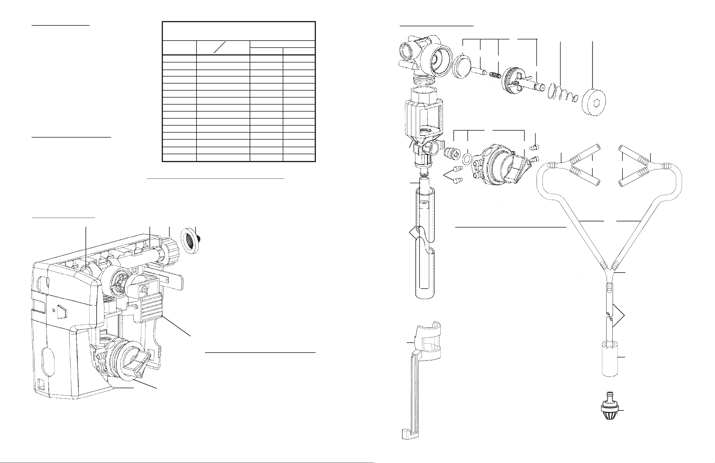
AccuDose Series Proportioner Models 3871AG-2 & 3872AG-2
with HydroGapTM Air Gap Eductors
Package Should Contain:
1. Proportioner unit.
2. Chemical inlet tubing
assembly with foot valve
& weight.
3. Discharge tube.
4. Metering tip kit.
5. Mounting hardware.
6. Hook for discharge tube
(Model 3871AG-2 only).
7. Instruction sheet.
Hydro Systems 3798 Round Bottom Road, Cincinnati, OH 45244 s Phone: (513) 271-8800 sFax:(513) 271-0160
Clip or
bend
these
tabs to
depress
button
into locked
position.