NT 1101-J00 08.10 A65 - AS65 e
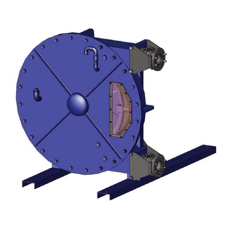
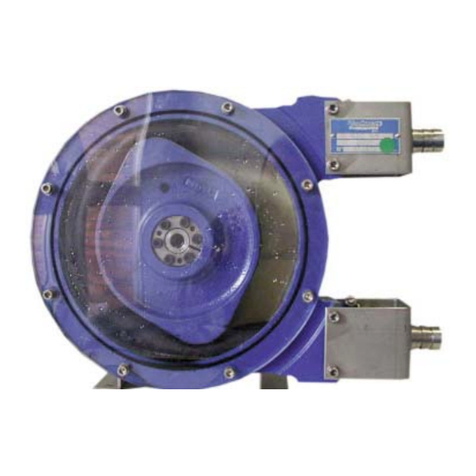
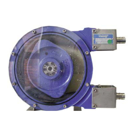
MOUVEX PERISTALTIC HOSE PUMP
SAFETY INSTRUCTIONS, STORAGE, INSTALLATION AND MAINTENANCE
MODELS : A65 -
AS65
TECHNICAL CHARACTERISTICS
• Maximum pump speed acceptable* :
• 60 tr/mn
(
rpm)
• Maximum running temperature * :
• NR hose . . . . . . . .70°C (158°F)
• NBR hose . . . . . .70°C (158°F)
• EPDM hose . . . . .80°C (176°F)
• Maximum discharge pressure acceptable*:
• 15 barg (217,5 psig)
• Minimum suction pressure acceptable :
• -0,9 barg (-13 psig)
• Cylinder capacity :
• 3,708 dm3 (0,980 gallon)
* CAUTION : Functional limitations indicated are strictly dependent on each
other, refer to TECHNICAL DATA § to define the limits of use for your
installation.
Pump n°:
Date of bringing into service :
SAFETY INFORMA
TIONS
Thisisa
SAFETY
ALERT
SYMBOL
When you see this symbol on the product, or in the manual, look
for one of the following signal words and be alert to the potential
for
personalinjury,deathormajorpropertydamage.
DANGER
Warns of hazards that WILL cause serious personal injury,
death or major property damage
W
ARNING
Warns of hazards that CAN cause serious personal injury,
death or major property damage.
CAUTION
Warns of hazards that CAN cause personal injury or property
damage.
TABLE OF CONTENTS Page
1. OVERALL DIMENSIONS . . . . . . . . . . . . . . . . . . . . . . . . . .3
1.1 A65 model . . . . . . . . . . . . . . . . . . . . . . . . . . . . . . . . . .
.3
1.2 AS65 model . . . . . . . . . . . . . . . . . . . . . . . . . . . . . . . . .
.4
2. INSTALLATION . . . . . . . . . . . . . . . . . . . . . . . . . . . . . . . . .5
2.1 Operator principle . . . . . . . . . . . . . . . . . . . . . . . . . . . .
.5
2.2 Hose compression . . . . . . . . . . . . . . . . . . . . . . . . . . .
.5
2.3 Pumped liquid . . . . . . . . . . . . . . . . . . . . . . . . . . . . . . .
.5
2.4 Pipe diameters . . . . . . . . . . . . . . . . . . . . . . . . . . . . . .
.5
2.5 Piping assembly . . . . . . . . . . . . . . . . . . . . . . . . . . . . .
.5
2.6 Direction of rotation . . . . . . . . . . . . . . . . . . . . . . . . . . .
.6
2.7 Liquids containing a high proportion of particles . . . .
.6
2.8 Working with vaccum on the suction side . . . . . . . . .
.6
2.9 Handling . . . . . . . . . . . . . . . . . . . . . . . . . . . . . . . . . . .
.6
2.10 Pump location . . . . . . . . . . . . . . . . . . . . . . . . . . . . . .
.6
2.11 Anchoring the pump units . . . . . . . . . . . . . . . . . . . . .
.7
2.12 Alignment of motor / pump and reduction gearbox /
pump shafts . . . . . . . . . . . . . . . . . . . . . . . . . . . . . . . . .7
2.13 Electric motors . . . . . . . . . . . . . . . . . . . . . . . . . . . . .
.7
3. USE . . . . . . . . . . . . . . . . . . . . . . . . . . . . . . . . . . . . . . . . . .8
3.1 Pump storage . . . . . . . . . . . . . . . . . . . . . . . . . . . . . . .
.8
3.2 Hose storage . . . . . . . . . . . . . . . . . . . . . . . . . . . . . . . .
.8
3.3 Pumping hot products . . . . . . . . . . . . . . . . . . . . . . . . .
.8
3.4 Pump filled with product at shutdown . . . . . . . . . . . . .
.8
3.5 Starting-up the pump . . . . . . . . . . . . . . . . . . . . . . . . .
.8
3.6 Shutting down the pump . . . . . . . . . . . . . . . . . . . . . . .
.8
3.7 In the event of the hose breaking . . . . . . . . . . . . . . . .
.8
3.8 Scrapping . . . . . . . . . . . . . . . . . . . . . . . . . . . . . . . . . .
.8
4. MAINTENANCE OPERATIONS . . . . . . . . . . . . . . . . . . . . .9
4.1 Replacing the hose . . . . . . . . . . . . . . . . . . . . . . . . . . .
.9
4.2 Re-assembling and disassembling the wheel . . . . . .12
4.3 Replacing the shoes . . . . . . . . . . . . . . . . . . . . . . . . . .12
4.4 Setting of pump at service pressure needed . . . . . . .13
5. TECHNICAL SPECIFICATIONS . . . . . . . . . . . . . . . . . . . .15
5.1 Characteristics . . . . . . . . . . . . . . . . . . . . . . . . . . . . . .16
5.2 Shimming the shoes . . . . . . . . . . . . . . . . . . . . . . . . . .16
6. MAINTENANCE . . . . . . . . . . . . . . . . . . . . . . . . . . . . . . . .17
6.1 Lubrication . . . . . . . . . . . . . . . . . . . . . . . . . . . . . . . . .17
6.2 Hose . . . . . . . . . . . . . . . . . . . . . . . . . . . . . . . . . . . . . .17
6.3 Seals . . . . . . . . . . . . . . . . . . . . . . . . . . . . . . . . . . . . . .17
7. TROUBLESHOOTING . . . . . . . . . . . . . . . . . . . . . . . . . . .18
8. CERTIFICATE OF CONFORMITY . . . . . . . . . . . . . . . . . .19
NOTES :
The MOUVEX peristaltic hose pumps MUST be installed on
systems specially designed by qualified staff. Installation
MUST comply with local standards, national rules and safety
regulations.
NOTICE
Indicates special instructions which are very important and
must be followed.
NOTES
The
numbers
writteninbold
charactersafter
part
namescorrespond
to reference numbers in the spare parts lists..
Photos and drawingsused in this IOM are not contractual.
This manual is designed for installation and start-up of the
peristaltic hose pumps. It MUST be supplied with the pump.
Maintenance of the peristaltic pumps must be carried out ONLY
by qualified personnel. This operation must comply with local
and national regulations as well as safety standards.
Read the whole manual and all the instructions and precau-
tions, BEFORE using any MOUVEX pumps.
Do not remove any warning and use stickers from the pumps.
