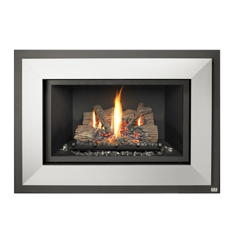
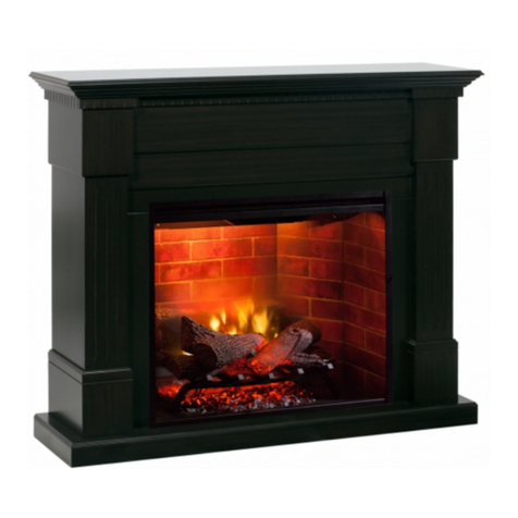
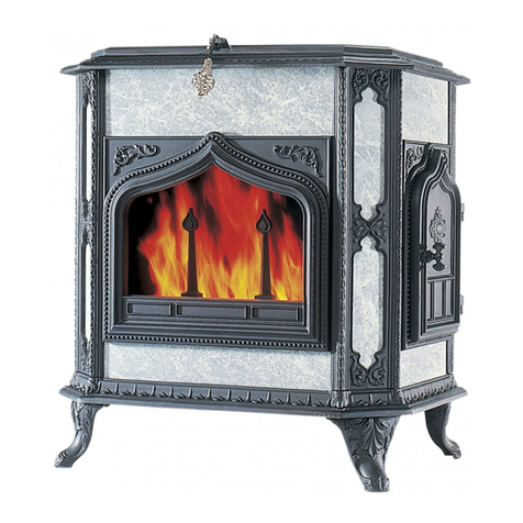
Dovre Malmo User manual

Malmø
Speksteenommanteling voor Attityd 200
Manteau en stéatite pour feu Attityd 200
Soapstone casing for Attityd 200
Specksteinummantelung für Attityd 200
MONTAGEVOORSCHRIFTEN
CONSIGNES DE MONTAGE
ASSEMBLY INSTRUCTIONS
MONTAGEVORSCHRIFTEN

2 03.27665.100
Inleiding
Lees dit boekje zorgvuldig, vooraleer u met de montage begint.
Wanneer u het product ontvangt is het belangrijk dat u nauwgezet controleert
of het product geen transportschade vertoont. Speksteen is een zachte steen-
soort, wees daarom voorzichtig bij het uitpakken.
Montagehandleiding
Voor de plaatsing en de werking van de Attityd 200 verwijzen wij naar de
“Installatievoorschriften en gebruiksaanwijzing Attityd 200”.
Toestel en ommanteling wegen samen 275 kg. Zorg ervoor dat de vloer vol-
doende draagkrachtig is.
Montage stap voor stap
De speksteen ommanteling is eenvoudig te monteren, u moet echter de in-
structies nauwkeurig opvolgen.
U gaat als volgt tewerk:
Voorbereiding:
Monteer de poten op een afstand van ca 320 mm voor u ze op het toestel
plaatst. U moet deze later nog precies afstellen.
Buig de steenhouders van plaatstalen beugels A,F en G met een schroeven-
draaier omhoog. Zie tekening “Plaatstalen onderdelen”.
Plaats nadien bodemplaat A . De minimum afstand tot een brandbare muur
moet minstens 100mm bedragen! Zet het toestel op de bodemplaat en zorg
dat het toestel loodrecht staat. Controleer dit met een waterpas! U kan nu ook
de lengte van de poten aanpassen. De afstand van grond tot bovenvlak van
het toestel moet 915mm bedragen (zie maatschets p12).
Opbouw:
fig 1: afstellen van de hoogte van het toestel. Na montage van de stenen zou-
den de zijstenen bovenaan moeten uitlijnen (u ziet dit na fig 9).
fig 2: monteer bevestigingsbeugels B op het toestel.
fig 3: monteer hitteschild D op rugplaat C met de 2 bovenste schroeven.
Monteer nadien het geheel tegen de bevestigingsbeugels B. U kan nu ook
de rugplaat op de bodemplaat vast bouten. Indien nodig moet het toestel
hiervoor nog verschoven worden. Alle schroef-bout verbindingen gebeuren
met de bijgeleverde flensbouten M6x10 en M6 moeren. Indien de buiten-

3 03.27665.100
luchttoevoer via de achterkant aangesloten wordt, moet onderaan de ronde
afdekplaat in de plaatstalen achterwand worden uitgedrukt. Indien de achter-
aansluiting van het toestel wordt gebruikt, moet bovenaan de afdekplaat uit
de achterwand gedrukt worden.
fig 4: plaats plaatstalen beugels W en Z’ op de bodemplaat. Beugel W past
onderaan in de rug. Speksteen 1 en 2 passen op deze beugels. Beide spekste-
nen worden bovenaan op hun plaats gehouden door plaatstalen beugel Y’ en
V. Beugel V past op zijn beurt in de plaatstalen rug. Herhaal deze stappen aan
de andere kant (met beugel V,W,Y en Z).
fig 5: u kan nu de voorste stenen - nr.3 - plaatsen. Doe dit van buiten naar
binnen.
fig 6: plaatstalen beugel E kan u nu over de stenen schuiven zodat deze wor-
den samengehouden.
fig 7: wanneer dit gebeurd is, kan u speksteen 4 plaatsen. Plaatstalen beugels
V passen bovenaan in de steen en passen achteraan in de plaatstalen rug.
fig 8: plaatstalen beugel F wordt gemonteerd op de rookvang van het toestel.
Dit gebeurd met de meegeleverde bouten M6x12 en sluitringen Ø6xØ18 .
fig 9: na deze handeling kan u speksteen 5 en 6 plaatsen. Plaatstalen beugel
X en X’ vormen de verbinding tussen beide stenen. Beugel W vormt de ver-
binding van speksteen 5 naar de plaatstalen rug.
fig 10: hierna kan u de voorste spekstenen – nr. 7 – plaatsen. Opnieuw van
buiten naar binnen. Indien u na plaatsing van de stenen teveel speling ziet
met de opstaande lippen van plaatstalen beugel F, kan u deze lippen nog ex-
tra aandrukken zodat de steen beter geklemd wordt.
fig 11: plaatstalen beugel G houd de stenen samen. U kan de opstaande lip-
pen extra aandrukken indien er na plaatsing teveel speling is met de spekste-
nen, zodat deze beter klemmen.
fig 12: de topstenen 8 en 9 kunnen geplaatst worden. Afhankelijk van de
versie (top – of achteraansluiting) is er al of niet een gat voorzien voor de
rookdoorvoer.
fig 13: als laatste wordt de vloerplaat H geplaatst. Deze wordt voor het toe-
stel geschoven.

4 03.27665.100
Introduction
Lisez bien attentivement ce petit manuel avant de commencer le montage.
A la réception du produit, il est important que vous vous assuriez que celui-ci
n’a pas subi le moindre dommage lors de son transport. La stéatite est une
pierre douce, soyez dès lors extrêmement prudent au moment du déballage.
Instructions de montage
Pour le placement et le fonctionnement du feu Attityd 200, voyez les “In-
structions d’installation et mode d’emploi Attityd 200”.
Le feu et son manteau pèsent, au total, 275 kg. Veillez dès lors à ce que le sol
soit suffisamment solide.
Montage étape par étape
Le manteau en stéatite est simple à monter. Il convient toutefois de respec-
ter scrupuleusement les instructions.
Procédez de la manière suivante :
Préparation :
Montez les pieds à une distance d’environ 320 mm avant de les placer sur
l’appareil. Vous devrez procéder à un réglage de précision plus tard.
À l’aide d’un tournevis, repliez vers le haut les colliers des pièces tôlées A,
F et G. Voir le schéma “Pièces tôlées”.
Placez ensuite la plaque de sol A. La distance minimale jusqu’au mur in-
flammable le plus proche doit être de 100 mm au moins ! Placez l’appareil
sur la plaque de sol et assurez-vous qu’il soit bien de niveau. Contrôlez à
l’aide d’un niveau à bulle ! À présent, vous pouvez régler la longueur des
pieds. La distance du sol à la surface supérieure de l’appareil doit être de
915 mm (voir le croquis coté en p 12).
Montage :
Fig. 1 : Réglage de la hauteur de l’appareil. Après le montage des pierres,
les pierres latérales doivent être alignées (comme vous pouvez le voir après
la fig. 9).
Fig. 2 : Montez les colliers de fixation B sur l’appareil.
Fig. 3 : Montez le bouclier thermique D sur la plaque dorsale C avec les 2
vis supérieures. Montez ensuite l’ensemble contre les colliers de fixation B.
Vous pouvez également fixer la plaque dorsale sur la plaque de sol. Si né-

5 03.27665.100
cessaire, l’appareil pourra encore être déplacé. Toutes les fixations par vis-
boulon se font à l’aide des boulons à bourrelet M6x10 et des écrous M6. Si
l’arrivée d’air extérieur est raccordée à l’arrière de l’appareil, il convient
d’emboutir le couvercle inférieur rond dans les éléments tôlés à l’arrière.
Si on utilise le raccordement arrière de l’appareil, il convient également
d’emboutir le couvercle de la paroi arrière.
Fig. 4 : Placez les colliers des pièces tôlées W et Z’ sur la plaque de sol. Le
collier W se place en dessous dans la plaque dorsale. Les pierres stéatites 1
et 2 se placent sur ces colliers. Les deux stéatites sont maintenues en place
par les colliers tôlés Y’ et V. Le collier V se place dans la pièce tôlée dor-
sale. Répétez ces étapes de l’autre côté (avec les colliers V, W, Y et Z).
Fig. 5 : vous pouvez maintenant placer les pierres frontales (no. 3). Procé-
dez de l’extérieur vers l’intérieur.
Fig. 6 : A présent, vous pouvez glisser le collier tôlé E sur les pierres pour
qu’elles tiennent ensemble.
Fig. 7 : Lorsque vous avez terminé, vous pouvez placer la stéatite 4. Les
colliers tôlés V se placent au-dessus dans la pierre et à l’arrière dans la
pièce tôlée dorsale.
Fig. 8 : Le collier tôlé F est monté sur l’avaloir de l’appareil. Pour cela,
utilisez les boulons M6x12 et les joints hermétiques Ø6xØ18 fournis.
Fig. 9 : Ensuite, vous pouvez placer les stéatites 5 et 6. Les colliers tôlés X
et X’ constituent le raccord entre ces deux pierres. Le collier W constitue le
raccord entre la stéatite 5 et la pièce tôlée dorsale.
Fig. 10 : Ensuite, vous pouvez placer la stéatite avant (no. 7). De nouveau,
de l’extérieur vers l’intérieur. Après le placement des pierres, si vous con-
statez un jeu trop important avec les mors supérieurs du collier tôlé F, vous
pouvez les serrer jusqu’à ce que la pierre soit bien fixée.
Fig. 11 : Le collier tôlé G maintient les pierres ensemble. Si le jeu avec les
stéatites est trop important après le placement, vous pouvez serrer davan-
tage les mors supérieurs pour que les pierres soient bien fixées.
Fig. 12 : Les pierres supérieures 8 et 9 peuvent être placées. En fonction
de la version (raccordement supérieur ou arrière), un trou est prévu pour le
passage de la fumée.
Fig. 13 : Finalement, vous pouvez placer la plaque frontale H. Elle est glis-
sée devant l’appareil.

6 03.27665.100
Introduction
Read this booklet carefully before starting assembly.
When you receive the product, it is important for you to inspect it thoroughly
to establish whether it has sustained any transport damage. Soapstone is a
soft stone, so be careful when removing the packaging.
Assembly manual
Please refer to the ‘Installation instructions and manual for Attityd 200’ for
the installation and operation of the Attityd 200.
Together, the device and casing weigh 275 kg. Make sure that the floor has
sufficient load-bearing capacity.
Step-by-step assembly
Assembling the soapstone casing is simple as long as you follow the in-
structions exactly.
Proceed as follows:
Preparation:
Assemble the legs to a height of approx. 320 mm before mounting them
onto the device. They will need to be adjusted later on.
Bend the lips of the sheet metal braces A, F and G upwards with a screw-
driver. See drawing “Sheet metal parts”.
Now mount base plate A. The minimum distance to a flammable wall must
be at least 100 mm! Position the device on the base plate and ensure it is
perfectly level. Check this with a spirit level! Now adjust the height of the
legs. The distance from the floor to the top of the device should measure
915 mm (see diagram p12).
Assembly:
Fig. 1: Adjust the height of the device. After being assembled the side sto-
nes should align at the top (see fig. 9).
Fig. 2: Mount attachment braces B onto the device.
Fig. 3: Attach heat shield D to the back plate C with the two top screws.
Then mount the whole piece onto the attachment braces B. The back plate
can now be bolted to the base plate. It is possible the device must be moved
to do so. The supplied flange bolts M6x10 and nuts M6 must be used for all
screw-bolt connections. If the outside air supply is to be connected at the

7 03.27665.100
rear, the round cover plate at the bottom of the sheet metal back plate must
be pushed out. If the rear connection of the device is to be used, the cover
plate at the top of the back plate must be pushed out.
Fig. 4: Position the sheet metal braces W and Z’ on the base plate. Brace
W fits in the back at the bottom. Soapstones 1 and 2 fit on these braces.
Both soapstones are held in place at the top by metal sheet braces Y’ and
V. Brace V fits in the sheet metal back. Repeat these steps at the other side
(with braces V, W, Y and Z).
Fig. 5: Now the front stones (no 3) can be put in place. Start with the one
on the outside.
Fig. 6: Now slide the sheet metal brace E over the stones so that they are
held together.
Fig. 7: After this is done, soapstone 4 can be put in place. The sheet metal
braces V fit in the stone at the top and in the sheet metal back at the rear.
Fig. 8: Sheet metal brace F is mounted on the flue of the device. For this the
bolts M6x12 and locking rings Ø6xØ18 that are supplied must be used.
Fig. 9: When this is done, soapstones 5 and 6 can be put in place. Sheet me-
tal brace X and X’ are used to connect these two stones. Brace W connects
soapstone 5 to the sheet metal back.
Fig. 10: Now the front soapstones (no 7) can be put in place. Again, start
with the one on the outside. If after putting the stones in place you see too
much play between the stones and the raised lips of sheet metal brace F,
you can put some extra pressure on these lips so that the stone is gripped
more tightly.
Fig. 11: Sheet metal brace G holds the stones together. You can put some
extra pressure on the raised lips to tighten their grip if there is too much
play between them and the stones.
Fig. 12: The top stones 8 and 9 can be put in place. Depending on the ver-
sion (top or rear connection), a smoke outlet opening may be provided.
Fig. 13: Floor plate H is installed last. Slide it in front of the device.

8 03.27665.100
Einführung
Lesen Sie diese Anleitung sorgfältig, bevor Sie mit der Montage beginnen.
Wenn Sie das Produkt erhalten, ist es äußerst wichtig, dass Sie gewissenhaft
kontrollieren, ob das Produkt keine Transportschäden aufweist. Speckstein
ist eine weiche Steinart, seien Sie deshalb vorsichtig beim Auspacken.
Montageanleitung
Für die Montage und den Betrieb des Attityd 200 verweisen wir auf die “In-
stallationsvorschriften und Gebrauchsanleitung Attityd 200”.
Das Gerät und die Ummantelung wiegen gemeinsam 275 kg. Sorgen Sie
dafür, dass der Fußboden über genügend Tragkraft verfügt.
Montage Schritt-für-Schritt
Die Specksteinummantelung ist einfach zu montieren, wobei Sie allerdings
die Anleitungen sorgfältig befolgen müssen. Sie gehen folgendermaßen vor:
Vorbereitung:
Montieren Sie die Füße in einem Abstand von rund 320 mm, bevor Sie diese
am Gerät anbringen. Sie müssen sie später noch genau einstellen.
Beugen Sie die Steinhalter der Stahlblechbügel A, F und G mit einem
Schraubenzieher nach oben. Siehe Skizze “Stahlblechteile”.
Montieren Sie danach die Bodenplatte A. Der Mindestabstand zu einer bren-
nbaren Wand muss mindestens 100 mm betragen! Geben Sie das Gerät auf
die Bodenplatte und sorgen Sie dafür, dass das Gerät senkrecht steht. Kont-
rollieren Sie dies mit einer Wasserwaage! Sie können nun auch die Länge
der Füße anpassen. Der Abstand vom Boden zur Oberseite des Gerätes muss
915 mm betragen (siehe Maßskizze S. 12).
Aufbau:
Abb. 1: Einstellung der Gerätehöhe. Nach der Montage der Steine müssten
die Seitensteine oben abgeglichen sein (Sie sehen dies nach Abb. 9).
Abb. 2: Montieren Sie die Befestigungsbügel B am Gerät.
Abb. 3: Montieren Sie das Hitzeschild D auf der Rückenplatte C mit den 2
obersten Schrauben. Montieren Sie danach das Ganze an die Befestigungs-
bügel B. Sie können jetzt auch die Rückenplatte auf der Bodenplatte fest-
schrauben. Nötigenfalls muss das Gerät zu diesem Zweck noch verschoben
werden. Alle Schrauben-Bolzenverbindungen erfolgen mit den mitgeliefer-

9 03.27665.100
ten Flanschbolzen M6x10 und M6-Muttern. Wenn die Frischluftzufuhr über
die Rückseite angeschlossen wird, muss unten die runde Abdeckplatte in der
Stahlblech-Rückwand herausgedrückt werden. Wenn der hintere Anschluss
des Gerätes verwendet wird, muss oben die Abdeckplatte aus der Rückwand
gedrückt werden.
Abb. 4: Geben Sie die Stahlblechbügel W und Z’ auf die Bodenplatte. Bügel
W passt unten in den Rücken. Speckstein 1 und 2 passen auf diese Bügel.
Beide Specksteine werden oben durch die Stahlblechbügel Y’ und V an Ort
und Stelle gehalten. Bügel V passt ebenso in den Stahlblechrücken. Wieder-
holen Sie diese Schritte auf der anderen Seite (mit Bügel V, W, Y und Z).
Abb. 5: Sie können jetzt die vordersten Steine (Nr. 3) montieren. Tun Sie
dies von außen nach innen.
Abb. 6: Stahlblechbügel E kann jetzt über die Steine geschoben werden,
sodass diese zusammengehalten werden.
Abb. 7: Wenn dies passiert ist, können Sie Speckstein 4 anbringen. Die
Stahlblechbügel V passen oben in den Stein und passen hinten in den Stahl-
blechrücken.
Abb. 8: Der Stahlblechbügel F wird auf dem Rauchfang des Gerätes mon-
tiert. Dies erfolgt mit den mitgelieferten Bolzen M6x12 und der Unterleg-
scheibe Ø6xØ18.
Abb. 9: Nach dieser Handlung können Sie Speckstein 5 und 6 anbringen.
Die Stahlblechbügel X und X’ bilden die Verbindung zwischen beiden
Steinen. Bügel W bildet die Verbindung zwischen Speckstein 5 und dem
Stahlblechrücken.
Abb. 10: Danach können Sie die vordersten Specksteine (Nr. 7) anbringen.
Erneut von außen nach innen. Wenn Sie nach der Montage der Steine zuviel
Spielraum mit den offenen Lippen des Stahlblechbügels F sehen, können
Sie diese Lippen noch zusätzlich andrücken, sodass der Stein besser einge-
klemmt wird.
Abb. 11: Der Stahlblechbügel G hält die Steine zusammen. Sie können die
senkrechten Lippen zusätzlich andrücken, wenn nach der Montage zuviel
Spielraum mit den Specksteinen besteht, sodass diese besser klemmen.
Abb. 12: Die obersten Steine 8 und 9 können montiert werden. Abhängig
von der Version (Anschluss oben oder hinten) ist eventuell eine Öffnung für
die Rauchdurchfuhr vorgesehen.
Abb. 13: Zuletzt wird die Bodenplatte H montiert. Sie wird vor das Gerät
geschoben.

10 03.27665.100
w
x
v
v
v
v
w
x’
b
b
v
v
y
y’
w
z’
z
e
a
h
g
f
d
c
4x w
6x v
z’
z
y’
y
x’
x

11 03.27665.100
Plaatstalen onderdelen
Pièces tolées
Steel sheet parts
Stahlblech-Bestandteile
f g
a

12 03.27665.100

13 03.27665.100
1
B
B
2
C
D
3
bb
c
d

14 03.27665.100
A
1
2
Z’ W
V
Y’
E
4
V
V
F
5
6
W
W
X’
X
5
6
45
6 7
8 9
y’ v
z’ w
a
2
1
3
3
3
3
e4
vv
f
w
w
x
x’
5
5
6
6

15 03.27665.100
10 11
12 13

In het kader van een continue productverbetering, kunnen specificaties van het ge-
leverde toestel afwijken van de beschrijving in deze brochure, zonder voorafgaande
kennisgeving.
Dans le cadre d’une amélioration constante des produits, les spécifications du produit
livré peuvent différer du contenu de ce document, sans avis préalable.
Due to continuous product improvement, specifications of the delivered product
may differ from the content of this booklet, without further notice.
Im Rahmen kontinuerlicher Produktverbesserung, können Specifikationen des gelie-
fertes Produktes von den Beschreibungen in dieser Broschure abweichen.
DOVRE N.V. Tel : +32 (0) 14 65 91 91
Nijverheidsstraat 18 Fax : +32 (0) 14 65 90 09
03.27665.100 1204
Table of contents
Languages:
Popular Fireplace Accessories manuals by other brands

Rinnai
Rinnai Ember 600 Installation

Woodstock Soapstone
Woodstock Soapstone W-232 Replacement manual

Valor
Valor H3 Series installation manual

Town & Country Fireplaces
Town & Country Fireplaces 22150050 instructions

Hearth & Home
Hearth & Home SRV2384-070 Log Placement Instructions

Napoleon
Napoleon PSL36SS installation instructions

Euroheat
Euroheat IN1042 installation instructions

Napoleon
Napoleon BHD4 SEE-THRU installation instructions

Valor
Valor 720SWK installation instructions

pleasant hearth
pleasant hearth 1085 manual

Valor
Valor MADRONA Series installation instructions

Legend Industries
Legend Industries 745 Clearview Front Kit installation instructions